How to Design a Solar Drip Irrigation System for a Nigerian Farm(Powerful Tips)
Learn how to design a solar drip irrigation system in Nigeria. This complete guide covers crop water demand, pump sizing, solar array sizing, drip network layout, filtration, header tanks, zoning, and fertigation for efficient dry-season farming.
Drip irrigation is the most water-efficient way to grow crops. Solar drip irrigation takes it further: no fuel cost, no generator noise, no utility bills, and water delivered exactly where each plant needs it, every day, as long as the sun shines.
In Nigeria, solar drip irrigation is a practical solution for vegetable farms, smallholder plots, orchards, and greenhouse operations. The technology is not new, but very few Nigerian farmers or installers understand how to design a system that actually works reliably through both wet and dry season.
This guide gives you the complete design process. From calculating your crop water demand to selecting your pump, sizing your panels, and laying out your drip lines. Every number and decision in this guide is grounded in Nigerian farming conditions.
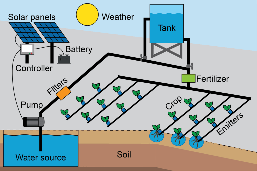
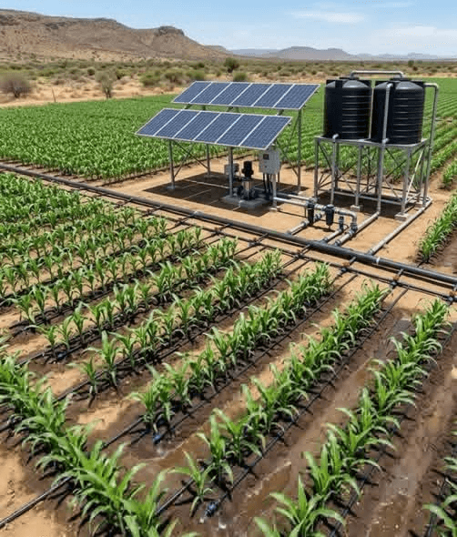
A solar drip irrigation system has five main components working together:
Solar array: panels that generate DC electricity from sunlight
Pump and controller: moves water from the source into the distribution system
Header tank or pressure tank: stores water and provides consistent pressure to the drip lines
Mainline and submain pipes: carry water from the tank to the field
Drip laterals and emitters: deliver water directly to the root zone of each plant
The solar array powers the pump during daylight hours. The pump fills the header tank. Gravity or a pressure regulator then distributes water through the drip network at low pressure. Each emitter delivers a controlled flow of 1 to 4 litres per hour directly to the soil beside each plant.
Drip irrigation delivers water at the root zone, not at the surface. This eliminates evaporation losses, reduces weed growth between rows, and can reduce water consumption by 30 to 60 per cent compared to flood or sprinkler irrigation.
Every other number in this design depends on how much water your crops actually need per day. This is your starting point.
Crop water demand is expressed in millimetres per day (mm/day), which is equivalent to litres per square metre per day. A demand of 5 mm/day means each square metre of planted area needs 5 litres of water per day.
Crop Water Demand Reference Table for Nigerian Conditions
Crop
Growth Stage
Water Demand (mm/day)
Litres per m2 per day
Season in Nigeria
Tomato
Vegetative
3 to 4
3 to 4 L
Oct to Feb (dry season)
Tomato
Fruiting
5 to 7
5 to 7 L
Peak demand period
Pepper (tatashe/shombo)
Full growth
4 to 6
4 to 6 L
Year-round
Watermelon
Vegetative
3 to 5
3 to 5 L
Dec to Mar
Watermelon
Fruiting
6 to 8
6 to 8 L
Peak demand period
Cucumber
Full growth
4 to 6
4 to 6 L
Year-round
Maize
Vegetative
4 to 5
4 to 5 L
Dry season cultivation
Maize
Silking/tasselling
7 to 8
7 to 8 L
Critical period
Onion
Bulbing stage
5 to 6
5 to 6 L
Nov to Feb
Cabbage/lettuce
Head formation
4 to 5
4 to 5 L
Oct to Mar
Cassava
Establishment
2 to 3
2 to 3 L
Early growth only
Cowpea
Flowering/podding
4 to 5
4 to 5 L
Dry season
These values are based on FAO Irrigation and Drainage Paper 56 (FAO-56), the global standard for crop water requirement calculation. For full evapotranspiration data by Nigerian state, refer to: FAO AQUASTAT Nigeria Irrigation Data.
How to Calculate Total Daily Water Demand
Once you know your crop demand per square metre, multiply by your total planted area.
Daily Water Demand (litres) = Crop Demand (mm/day) x Planted Area (m2)
Example: A 0.5-hectare tomato farm at peak fruiting stage with 6 mm/day demand:
Planted area: 0.5 ha = 5,000 m2
Demand: 6 mm/day = 6 L/m2/day
Total daily demand: 6 x 5,000 = 30,000 litres per day
That is 30,000 litres of water your pump must deliver every day. This number drives every other component sizing decision in your system.
Accounting for System Efficiency Losses
No drip system is 100 per cent efficient. Water is lost to pipe leakage, emitter variation, and occasional flushing. Add a 15 per cent efficiency buffer to your demand figure.
Design Demand = Daily Water Demand x 1.15
For the tomato example above: 30,000 x 1.15 = 34,500 litres per day design demand.
Step 2: Calculate Required Pump Flow Rate
The pump only runs during daylight hours when solar energy is available. Divide your design demand by the number of peak sun hours to get the minimum flow rate your pump must deliver.
Minimum 8,000 L/hr (8 m3/hr) at your operating head
An 8 m3/hr pump at the correct head is a large pump for a half-hectare farm. This is the reality of dry-season irrigation in northern Nigeria. Farmers who undersize their pump run out of water before the day’s irrigation cycle is complete.
Zoning: How to Reduce Pump Size Using Irrigation Zones
You do not have to irrigate the entire farm simultaneously. Dividing the farm into irrigation zones allows you to use a smaller pump and run each zone sequentially during the day.
If the 0.5 ha tomato farm is divided into 3 equal zones of approximately 1,667 m2 each:
Demand per zone: 6 x 1,667 = 10,002 litres per zone
Each zone runs for 1.5 hours out of the 4.5 available peak sun hours
Zoning is the most powerful tool for reducing pump size and cost in large solar drip irrigation systems. A well-zoned system can use a pump 40 to 60 per cent smaller than an unzoned design.
Zone sizing must account for the drip lateral pressure requirements. All emitters in an active zone must receive adequate pressure simultaneously. Do not create zones so large that pressure drops below emitter operating range at the far end of the field.
Step 3: Design the Drip Network
The drip network consists of mainlines, submains, lateral lines, and emitters. Each component must be sized correctly or pressure and flow will be uneven across the field.
Understanding Drip System Pressure Requirements
Drip emitters operate within a specific pressure range. Operating below minimum pressure reduces flow. Operating above maximum pressure causes leaks and shortened emitter life.
Emitter Type
Operating Pressure Range
Flow Rate at Rated Pressure
Non-compensating drip emitter
0.5 to 1.5 bar (5 to 15 m head)
1 to 4 L/hr depending on model
Pressure-compensating emitter
0.5 to 4.0 bar (5 to 40 m head)
Constant flow regardless of pressure variation
Inline drip tape (thin-wall)
0.3 to 0.8 bar (3 to 8 m head)
0.3 to 1.5 L/hr per emitter
Micro-spray / wobbler
1.5 to 3.0 bar (15 to 30 m head)
30 to 200 L/hr per head
For most Nigerian vegetable farms, inline drip tape or pressure-compensating emitters are the correct choice. Pressure-compensating emitters are strongly recommended for any field longer than 50 metres or with any slope, as they maintain uniform application rates regardless of pressure variation along the lateral.
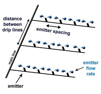
Lateral Line Spacing and Emitter Spacing
Lateral lines run along plant rows. The spacing between laterals and between emitters on each lateral depends on your crop type and soil texture.
Crop
Row Spacing
Lateral Spacing
Emitter Spacing on Lateral
Tomato
75 cm rows
1 lateral per row (75 cm)
30 to 45 cm between emitters
Pepper
60 cm rows
1 lateral per row (60 cm)
30 to 40 cm between emitters
Watermelon
1.5 to 2 m rows
1 lateral per row
60 to 90 cm between emitters
Cucumber
75 to 100 cm rows
1 lateral per row
30 to 45 cm between emitters
Onion
20 to 25 cm rows
1 lateral per 2 rows (40-50 cm)
20 to 30 cm between emitters
Maize
75 cm rows
1 lateral per 2 rows (150 cm)
30 to 45 cm between emitters
Cabbage
60 cm rows
1 lateral per row (60 cm)
40 to 50 cm between emitters
In clay soils (common in much of the Middle Belt and South-West), water spreads laterally more than in sandy soils. You can increase emitter spacing by 20 to 30 per cent. In sandy soils (common in the North), water moves primarily downward. Reduce emitter spacing to compensate.
Calculating Total Number of Emitters
Once you know your lateral spacing and emitter spacing, calculate the total emitter count for the field.
Example: 1 ha tomato field, rows at 75 cm, emitters at 40 cm on lateral
Field dimensions assumed: 100 m x 100 m
Number of rows: 100 m / 0.75 m = 133 rows
Length of each lateral: 100 m
Emitters per lateral: 100 m / 0.40 m = 250 emitters
Total emitters: 133 x 250 = 33,250 emitters
This total emitter count tells you the total flow rate when all emitters are running simultaneously, which determines your zone sizing.
Calculating Total System Flow Rate from Emitters
Total Flow Rate (L/hr) = Number of Active Emitters x Emitter Flow Rate (L/hr)
If each emitter delivers 2 L/hr and you have 33,250 emitters, running the full field simultaneously requires 66,500 L/hr. That is 66.5 m3/hr. No small farm pump can deliver that. This is exactly why zoning is essential.
With 4 zones of roughly equal size, each zone has approximately 8,312 emitters. Zone flow rate: 8,312 x 2 = 16,624 L/hr (16.6 m3/hr). Your pump must deliver 16.6 m3/hr at your operating head.
Step 4: Size the Mainline and Submain Pipes
Undersized pipes cause excessive friction losses that reduce pressure at the emitters. Oversized pipes waste money. Use this reference table for initial selection, then verify with friction loss calculations for your specific layout.
Pipe Size (OD)
Material
Max Recommended Flow
Typical Application
25 mm (1 inch)
HDPE or uPVC
1.5 m3/hr
Lateral lines, short submains
32 mm (1.25 inch)
HDPE or uPVC
2.5 m3/hr
Short submains, small zones
40 mm (1.5 inch)
HDPE or uPVC
4.5 m3/hr
Submains up to 100 m
50 mm (2 inch)
HDPE or uPVC
8 m3/hr
Main submains, moderate flow
63 mm (2.5 inch)
HDPE or uPVC
14 m3/hr
Mainlines, large zones
75 mm (3 inch)
HDPE or uPVC
22 m3/hr
Primary mainlines, large farms
90 mm (3.5 inch)
HDPE or uPVC
32 m3/hr
Large commercial mainlines
110 mm (4 inch)
HDPE or uPVC
50 m3/hr
Major distribution mains
Always select pipe size to keep flow velocity below 1.5 m/s. Higher velocities cause water hammer, noise, and accelerated pipe wear. For drip irrigation mainlines, 1.0 to 1.2 m/s is a comfortable operating velocity.
HDPE vs uPVC for Nigerian Farm Conditions
Property
HDPE Pipe
uPVC Pipe
UV resistance
Good. Black HDPE handles direct sunlight.
Poor. Grey uPVC degrades in direct sun. Must be buried or shaded.
Flexibility
Flexible. Easier to lay over uneven terrain.
Rigid. Needs fittings for any direction change.
Cost
Slightly higher than uPVC for same size.
Lower unit cost.
Jointing
Compression fittings or fusion welding.
Solvent cement or compression fittings.
Expansion
Expands significantly with heat.
Less expansion than HDPE.
Best use in Nigeria
Above-ground runs, exposed mainlines.
Buried mainlines, shaded runs.
For any pipe run exposed to direct Nigerian sunlight, use black HDPE. Grey uPVC pipes become brittle within 12 to 18 months of UV exposure and develop cracks and leaks. This failure mode is extremely common on Nigerian farms that start with uPVC above ground.
Step 5: Design the Header Tank and Pressure System
The header tank is the pressure source for the drip network. Water from the pump fills the tank. Gravity pressure from the tank then drives the drip laterals.
Required Header Tank Elevation
For gravity-fed drip systems, the header tank must be elevated above the field to create pressure. The relationship between height and pressure is direct: every 10 metres of elevation creates 1 bar (100 kPa) of pressure.
Pressure from elevation: 1 metre of height = 0.1 bar = 10 kPa of pressure at the tank outlet
For non-compensating drip emitters requiring 0.5 to 1.0 bar, the tank outlet must be 5 to 10 metres above the emitters at the far end of the field. For drip tape requiring 0.3 to 0.5 bar, 3 to 5 metres of elevation is sufficient.
Target Pressure at Emitter
Required Tank Elevation Above Emitter
Notes
0.3 bar (drip tape)
3 metres minimum
For very flat terrain only
0.5 bar (standard drip emitters)
5 metres minimum
Most common drip emitter requirement
0.8 bar (recommended operating point)
8 metres
Provides buffer for friction losses
1.0 bar (high-end emitters)
10 metres
For long lateral runs with friction losses
If your farm is on sloped terrain, the tank elevation is measured above the highest emitter, not the lowest. Emitters at lower elevation will have excess pressure. Use pressure regulators on submains to prevent over-pressure at low points on sloped fields.
Header Tank Sizing for Drip Irrigation
The header tank must store at least one zone’s worth of water plus a buffer. If your pump and tank fill simultaneously with zone irrigation, you can use a smaller tank. If the tank must be filled before irrigation starts, size it for the full day’s demand.
Scenario
Minimum Tank Size
Pump fills tank, gravity feeds drip (sequential)
1 full zone demand x 1.5 safety factor
Pump stopped, tank feeds drip only
Full daily demand x 1.5 safety factor
Night watering or early morning zones
Full daily demand + overnight buffer
Fertigation system (nutrients in tank)
Match zone demand exactly for dosing accuracy
For a 3-zone system where each zone uses 10,000 litres and zones run sequentially while the pump refills the tank between zones, a 15,000 to 20,000 litre header tank is appropriate.
For comprehensive tank sizing methodology including safety margins and buffer calculations, see the tank sizing section in: Solar Water Pump System in Nigeria.
Step 6: Select and Size the Solar Pump
With your flow rate requirement and operating head calculated, you can now select the correct pump and solar array.
Determine the Operating Head for a Farm Pump
For a surface water source (river or canal), the operating head is simply the height from the water surface to the inlet of the header tank, plus pipe friction losses.
For a borehole source, use the full Total Dynamic Head calculation from the borehole to the header tank.
Farm Pump Operating Head = Water Source to Tank Elevation + Friction Losses in Rising Main
Example: River surface to header tank inlet height = 5 m. Rising main friction = 2 m. Total operating head = 7 m. Very low head for a surface water application.
Pump Selection for Common Nigerian Farm Sizes
Farm Size
Crop (Dry Season)
Daily Demand
Pump Needed
Solar Array
0.25 ha
Tomato/pepper
15,000 L/day
4 to 5 m3/hr at 10 m head
800W to 1,200W
0.5 ha
Tomato/pepper
30,000 L/day
8 to 10 m3/hr at 10 m head
1,600W to 2,400W
1 ha
Mixed vegetables
60,000 L/day
15 to 20 m3/hr at 10 m head
3,200W to 4,800W
2 ha
Mixed vegetables
120,000 L/day
30 to 40 m3/hr at 10 m head
6,400W to 9,600W
5 ha (zoned x5)
Vegetables/maize
250,000 L/day
50 m3/hr at 10 m head (zoned)
10,000W to 16,000W
These figures assume surface water source at 10 m head and harmattan-adjusted 4.5 peak sun hours. For borehole sources, operating head will be significantly higher and pump and array sizes must be recalculated accordingly.
For pump arrays on farms, fixed tilt is standard. The optimal tilt angle for maximum annual energy production in Nigeria is approximately equal to your site’s latitude, adjusted slightly toward the equator.
This is the most frequently skipped component in Nigerian solar drip installations. It is also the reason most drip systems fail within the first growing season.
Drip emitters have very small orifices, typically 0.3 to 1.5 mm in diameter. Any particle or organic matter larger than the orifice will block the emitter. Once blocked, that emitter stops delivering water, and the crop beside it dies from water stress while every other plant looks fine.
Clogged emitters are irreversible in thin-wall drip tape. In inline emitter systems, you must flush or replace the entire lateral. Proper filtration prevents this entirely.
Filtration Requirements by Water Source
Water Source
Filtration Required
Recommended Filter Type
Borehole (clean groundwater)
Minimum 120 mesh screen filter
Disc filter or screen filter at header tank inlet
Borehole (sandy/turbid water)
Sand media filter + 120 mesh secondary
Two-stage: sand tank then disc filter
River or canal (surface water)
Sand media filter + disc filter + secondary screen
Three-stage system. Algae and organic load is high.
Open well
Sand media filter + 120 mesh secondary
Two-stage. Risk of algae and organic matter.
Rainwater harvesting
Settling tank + 200 mesh screen
Low organic load but fine sediment possible
Install the primary filter at the pump outlet, before the water enters the header tank. Install a secondary screen filter at each zone valve inlet. This two-stage approach ensures that even if coarse particles bypass the primary filter, they are caught before entering the laterals.
Clean disc filters and screen filters by backflushing every two to four weeks, or more frequently during peak dust season. Sand media filters require backflushing based on pressure differential reading, not time.
Step 8: Design the Fertigation System (Optional but Recommended)
Fertigation means applying fertiliser through the drip system. Nutrients are dissolved in a concentrated solution in a tank and injected into the water stream at a controlled rate. Every plant receives fertiliser directly at its roots, in the exact amount needed, with no surface broadcast waste.
For Nigerian vegetable farmers, fertigation with water-soluble NPK fertilisers can reduce fertiliser cost by 20 to 40 per cent compared to broadcast application, because root uptake efficiency is dramatically higher.
Fertigation Equipment
Venturi injector: the simplest and most common for small farms. Creates a pressure differential that draws fertiliser solution into the water stream. No electricity required. Suitable for up to 2 hectares.
Fertiliser tank (bypass): a pressurised tank in-line with the system. Water flows through it, dissolving fertiliser. Simple but concentration decreases over time during the irrigation cycle.
Electric dosing pump: the most accurate option. Injects fertiliser at a precise rate regardless of system flow rate. Required for large farms or high-value crops where uniform nutrition is critical.
Always install the fertiliser injection point downstream of the filtration system, not upstream. Fertilisers can cause chemical precipitation that blocks filter media and emitters.
Complete System Layout: 0.5 Ha Tomato Farm in Kaduna
Here is a complete design summary for a working solar drip irrigation system for a 0.5-hectare tomato farm in Kaduna State, drawing water from a borehole.
Farm Parameters
Farm size: 0.5 ha (5,000 m2), roughly 100 m x 50 m
Crop: Tomato, peak fruiting demand 6 mm/day
Water source: Borehole, static water level 45 m, pump setting depth 60 m
Header tank location: 6 m elevated steel frame beside borehole
Soil type: Sandy loam (moderate lateral water spread)
Location: Kaduna, 10.5 degrees N, harmattan-adjusted peak sun hours: 4.5 hr
Water Demand Calculation
Parameter
Value
Raw daily demand
6 mm/day x 5,000 m2 = 30,000 litres
Design demand (x1.15)
34,500 litres per day
Number of irrigation zones
3 zones (each approx 1,667 m2)
Demand per zone
34,500 / 3 = 11,500 litres per zone
Zone irrigation time (equal split)
1.5 hours per zone over 4.5 hour sun window
Required flow rate per zone
11,500 / 1.5 = 7,667 L/hr = 7.7 m3/hr
Drip Network Design
Component
Specification
Row spacing
75 cm (tomato standard)
Number of rows
50 m / 0.75 m = 67 rows per zone (approx)
Lateral length
100 m per lateral
Emitter type
Pressure-compensating inline emitter, 2 L/hr
Emitter spacing
40 cm on lateral
Emitters per lateral
100 / 0.40 = 250 emitters
Emitters per zone
67 rows x 250 emitters = 16,750 emitters
Zone flow rate (all emitters)
16,750 x 2 L/hr = 33,500 L/hr (33.5 m3/hr)
Zone flow rate with irrigation time factor
7.7 m3/hr pump delivers 11,500 L in 1.5 hours
Emitter activation
All emitters on, flow rate per emitter matches pump delivery / emitter count
Note: The pump delivers 7.7 m3/hr which distributes across all active emitters in the zone. Each emitter receives approximately 0.46 L/hr at this flow rate, below the 2 L/hr rated output. For full 2 L/hr operation, a higher-flow pump or fewer emitters per zone is needed. This is a common design trade-off between pump cost and drip output rate.
Pump and Solar Array
Component
Specification
Borehole TDH
60 m depth + 6 m tank elevation + 4 m friction = 70 m
Required pump
7.7 m3/hr at 70 m TDH minimum
Pump selection
1.5 HP AC submersible with VFD, confirmed from performance curve
Motor wattage
1,100W
Array minimum (x1.5 startup)
1,100 x 1.5 = 1,650W
Array with harmattan buffer (x1.30)
1,650 x 1.30 = 2,145W
Panel configuration
6 x 400W monocrystalline = 2,400W
Header tank size
15,000 litres (polyethylene tank on 6 m steel frame)
Mainline pipe
63 mm HDPE from borehole to tank, then to field
Filtration
Sand media filter + 120 mesh disc filter at tank outlet
Zone valves
3 x manual ball valves (or solenoid valves if automated)
Before purchasing any equipment for a solar drip irrigation system in Nigeria, confirm each of these steps is complete:
Calculate crop water demand in mm/day for your specific crop and growth stage
Multiply by planted area to get total daily demand in litres
Add 15 per cent efficiency buffer to get design demand
Divide by harmattan-adjusted peak sun hours to get required pump flow rate
Divide the farm into irrigation zones to reduce pump size
Select emitter type and confirm operating pressure range
Calculate lateral spacing and emitter spacing for your crop and soil type
Size mainline and submain pipes to keep velocity below 1.5 m/s
Design header tank elevation to meet emitter pressure requirement
Size header tank for at least 1 full zone plus 50 per cent buffer
Calculate pump TDH from water source to header tank
Select pump from performance curve at your TDH and required flow rate
Size solar array at 1.5x motor wattage, then add 30 per cent harmattan buffer
Install primary filtration at pump outlet and secondary filter at each zone inlet
Install zone valves (manual minimum, solenoid preferred)
Frequently Asked Questions
Q1: How much water does a solar drip irrigation system use compared to flood irrigation?
A well-designed solar drip system typically uses 30 to 60 per cent less water than flood irrigation for the same crop and area. The exact saving depends on crop type, soil, and how well the flood system was managed before. On tomato farms in northern Nigeria where flood irrigation waste is high, drip systems commonly achieve 50 per cent water savings, meaning the same pump and water source can irrigate twice the area.
Q2: Can I use drip irrigation for all crops in Nigeria?
Drip irrigation works well for vegetables, fruits, orchards, and row crops including maize and cowpea. It is less practical for broadcast-seeded crops like rice, dense cover crops, or any crop where seeds are sown uniformly across the entire soil surface rather than in defined rows. For broadcast crops, micro-spray or overhead sprinkler irrigation is more appropriate.
Q3: How long does drip tape last in Nigerian conditions?
Thin-wall drip tape (0.1 to 0.15 mm wall thickness) typically lasts 2 to 4 growing seasons in Nigerian conditions with proper care. Thick-wall inline emitter laterals (0.5 to 1.2 mm) last 5 to 8 years. The main failure modes are UV degradation from direct sun exposure, physical damage from rodents (especially in the North where field rodents are active), and emitter clogging from poor filtration. Store drip tape out of direct sunlight between seasons.
Q4: Do I need a battery with a solar drip irrigation system?
Most solar drip irrigation systems are designed to operate without batteries. The header tank acts as the energy storage buffer: the pump fills it during the day and the tank supplies the drip network as needed. Batteries add significant cost and are not needed if the pump can fill the tank within the available sunlight hours. The only case where a battery might be justified is if you need automated night-time irrigation for high-value crops, which is rare in Nigerian conditions.
Q5: What is the minimum farm size that makes solar drip irrigation cost-effective in Nigeria?
From a purely economic standpoint, solar drip irrigation becomes cost-effective at approximately 0.25 hectares for high-value vegetable crops like tomato and pepper. At this scale, the water savings, reduced fertiliser waste from fertigation, and yield improvements from consistent watering typically recover the system cost within 2 to 3 growing seasons. For lower-value crops, the break-even farm size is higher.
Q6: How do I automate irrigation scheduling with a solar pump system?
The simplest automation uses a timer relay wired to solenoid zone valves. The pump runs during daylight hours and fills the header tank. The timer opens zone 1 valve at a preset time, closes it, opens zone 2, and so on. More sophisticated systems use an ESP32 or Arduino microcontroller with soil moisture sensors to trigger irrigation only when soil moisture drops below a set threshold. This adaptive approach reduces water use further and is increasingly being adopted on commercial vegetable farms in Kano and Kaduna.
Q7: What type of fertiliser can I use in fertigation through a drip system?
Only fully water-soluble fertilisers can be used in drip fertigation. Suitable products include monoammonium phosphate (MAP), monopotassium phosphate (MKP), potassium nitrate, calcium nitrate, and soluble NPK compound fertilisers. Never use suspension fertilisers, granular urea (unless confirmed fully dissolved), or fertilisers containing clay fillers. Check fertiliser solubility before use. Any undissolved material will block emitters.
Q8: Can my existing borehole pump handle drip irrigation as well as household supply?
It depends on your existing pump’s flow rate and head capacity. If your household borehole pump has surplus capacity beyond your daily household demand, you can add a drip system on the same pump and share the header tank. The pump must be able to meet the combined demand within the available sunlight hours. In most cases, a dedicated irrigation pump sized specifically for the farm is more reliable than sharing a domestic borehole pump.
I am Engr. Ubokobong Ekpenyong, a solar specialist and lithium battery systems engineer with over five years of hands-on experience designing, assembling, and commissioning off-grid solar and energy storage systems. My work focuses on lithium battery pack architecture, BMS configuration, and system reliability in off-grid and high-demand environments.
Contains information related to marketing campaigns of the user. These are shared with Google AdWords / Google Ads when the Google Ads and Google Analytics accounts are linked together.
90 days
__utma
ID used to identify users and sessions
2 years after last activity
__utmt
Used to monitor number of Google Analytics server requests
10 minutes
__utmb
Used to distinguish new sessions and visits. This cookie is set when the GA.js javascript library is loaded and there is no existing __utmb cookie. The cookie is updated every time data is sent to the Google Analytics server.
30 minutes after last activity
__utmc
Used only with old Urchin versions of Google Analytics and not with GA.js. Was used to distinguish between new sessions and visits at the end of a session.
End of session (browser)
__utmz
Contains information about the traffic source or campaign that directed user to the website. The cookie is set when the GA.js javascript is loaded and updated when data is sent to the Google Anaytics server
6 months after last activity
__utmv
Contains custom information set by the web developer via the _setCustomVar method in Google Analytics. This cookie is updated every time new data is sent to the Google Analytics server.
2 years after last activity
__utmx
Used to determine whether a user is included in an A / B or Multivariate test.
18 months
_ga
ID used to identify users
2 years
_gali
Used by Google Analytics to determine which links on a page are being clicked
30 seconds
_ga_
ID used to identify users
2 years
_gid
ID used to identify users for 24 hours after last activity
24 hours
_gat
Used to monitor number of Google Analytics server requests when using Google Tag Manager
1 minute
You can find more information in our Cookie Policy and .


")


")

")