What Is a BMS? 7 Essential Battery Management System Functions You Must Know
What is a BMS, learn how a Battery Management System works, and why it is essential for lithium batteries, solar systems, battery protection, balancing, and inverter communication.
Most people who buy a lithium battery focus on the capacity: 100Ah, 200Ah, 48V. They compare prices, check the brand name, and move on.
What they almost never think about is the small circuit board sitting between the cells and the terminals, the component that decides whether those cells survive long-term or destroy themselves within 18 months.
That component is the Battery Management System. And if you work with lithium batteries in any serious capacity, whether you are designing an off-grid solar system, building a battery pack, or managing a large energy storage installation understanding the BMS is not optional. It is foundational.
This guide explains what a BMS is, how it works at an engineering level, what happens when it fails or is absent, and why it is one of the most consequential components in any lithium battery system.
What a BMS Actually Is
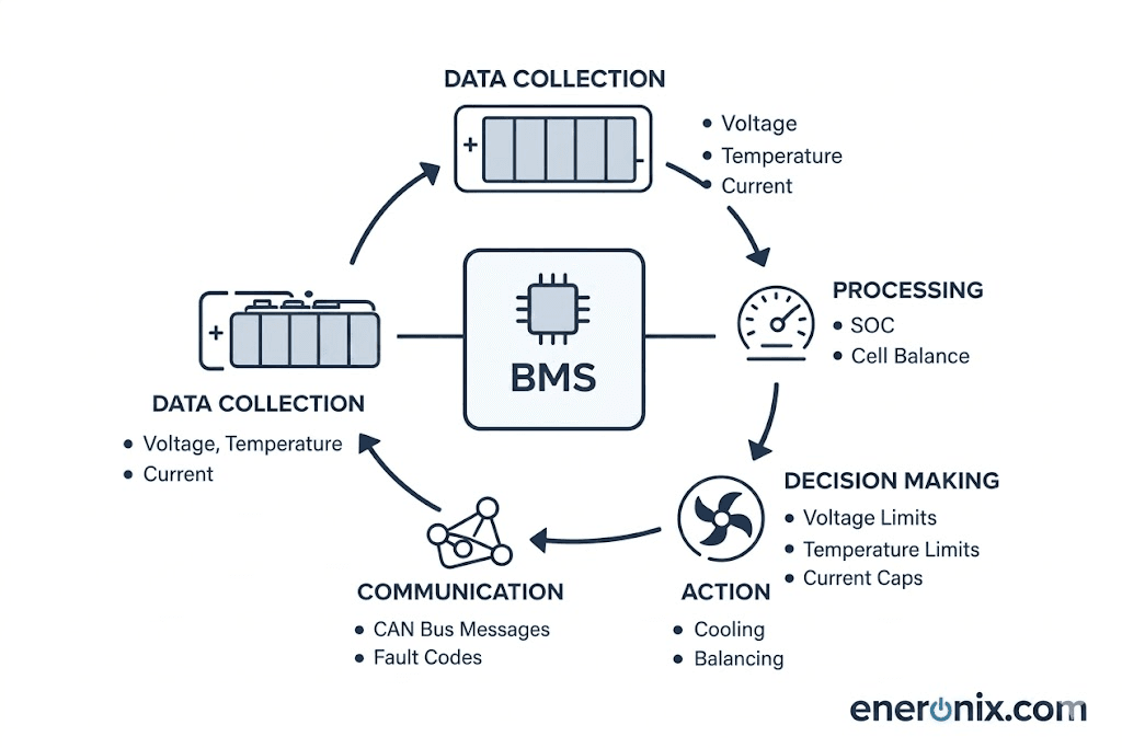
A Battery Management System is an electronic control unit that monitors, protects, and manages a lithium battery pack.
The name is slightly misleading because it implies the BMS manages the battery chemistry directly. It does not. What it manages is the electrical environment around the cell the conditions under which those cells charge, discharge, balance, and communicate.
Think of it this way: the cells store energy. The BMS governs how that energy moves in and out, and under what conditions the pack stays connected to the outside world.
Without a BMS, a lithium battery is a collection of cells with no supervisor. That is a dangerous situation. Lithium chemistries particularly NMC (Lithium Nickel Manganese Cobalt Oxide) and NCA (Lithium Nickel Cobalt Aluminium Oxide) can enter thermal runaway if overcharged or pushed past their discharge limits. Even the more thermally stable LiFePO4 chemistry can be permanently damaged by chronic cell imbalance, overvoltage, or deep discharge below its minimum threshold.
The BMS is the system that prevents all of this.
The Core Architecture: What Is Inside a BMS?
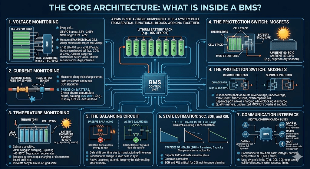
A BMS is not a single component. It is a system built from several functional blocks working together.
1. Voltage Monitoring
Every cell in a lithium pack has a nominal voltage and an operating range. For LiFePO4, that range is typically 2.5V (minimum) to 3.65V (maximum) per cell. For NMC cells, the range is typically 3.0V to 4.2V per cell.
The BMS continuously measures the voltage of each individual cell in the pack — not the pack voltage as a whole, but each cell independently.
This matters enormously. A 16S LiFePO4 pack running at 51.2V nominal contains 16 cells in series. If one of those cells climbs to 3.70V while the others sit at 3.40V, the pack as a whole may appear normal. But that single cell is overcharged. Without per-cell monitoring, no one would catch it until the cell vented, swelled, or failed catastrophically.
The voltage monitoring circuit uses a network of differential amplifiers or dedicated cell-monitoring ICs chips like the Texas Instruments BQ76940 or Analog Devices LTC6804 that are specifically designed to read cell voltages with millivolt accuracy across a stack of cells with widely different reference potentials.
2. Current Monitoring
The BMS measures the charge and discharge current flowing through the battery pack using a current sense resistor (shunt) or a Hall-effect sensor.
This serves two purposes. First, it enables the BMS to enforce current limits if the discharge current exceeds the rated maximum, the BMS disconnects the load. Second, the current measurement feeds the State of Charge algorithm, which tracks how much energy has entered and left the pack over time.
Current monitoring precision matters. A BMS using a cheap, high-resistance shunt will accumulate errors in its SOC calculation. Over weeks of use, those errors compound into a large SOC drift — the battery display says 60% but the pack is actually at 35%. If you have noticed your inverter showing battery percentage figures that do not match reality, a poorly calibrated BMS current sensor is frequently the cause. We covered this failure pattern in detail in our article on SOC drift in lithium battery systems.
3. Temperature Monitoring
Lithium cells are temperature-sensitive in both directions. At temperatures below 0°C, lithium-ion intercalation during charging becomes sluggish lithium plating can form on the anode, which is irreversible damage. At temperatures above 45–55°C (depending on chemistry), the electrolyte degrades faster and cycle life drops sharply.
The BMS uses thermistors, small temperature-sensing resistors placed at strategic points on the cell stack and near the MOSFET switches. When temperature exceeds the set limits, the BMS can reduce charging current, stop charging entirely, or disconnect the pack.
In Nigerian field conditions, ambient temperatures in unventilated battery enclosures regularly reach 40–50°C during the dry season. Without proper thermal monitoring and BMS response, cell degradation accelerates dramatically. This is one of the most common causes of early battery failure in off-grid solar systems across West Africa.
4. The Protection Switch: MOSFETs
The BMS uses power MOSFETs (Metal-Oxide-Semiconductor Field-Effect Transistors) as electronic switches on the charge and discharge paths.
When the BMS detects a condition that could damage the cells — overvoltage, undervoltage, overcurrent, short circuit, overtemperature — it turns off the relevant MOSFETs to disconnect the pack from the circuit.
There are two main configurations:
Common-port BMS: A single set of MOSFETs handles both charge and discharge current. Simpler and cheaper, but certain fault conditions can complicate behaviour — a charge FET fault can prevent discharge, and vice versa.
Separate-port BMS: Dedicated MOSFETs for charge current and separate MOSFETs for discharge current. Allows the BMS to permit charging while blocking discharge, which is important for systems where you want to allow solar charging even when the pack is in a discharged protection state.
The quality and rating of these MOSFETs is a significant differentiator between BMS tiers. Cheap BMS units use undersized MOSFETs that run hot under load, which degrades their switching performance over time and eventually leads to MOSFET failure, one of the most common BMS hardware faults in the field.
5. The Balancing Circuit
Cells in a battery pack are never perfectly identical. They come from the factory with slight differences in capacity, internal resistance, and self-discharge rate. Over time, these differences cause the cells to drift apart in state of charge some cells charge faster and hit the high voltage limit while others are still lower.
The balancing circuit redistributes charge between cells to keep them in sync. There are two types:
Passive balancing burns excess energy from higher-voltage cells through small resistors, bringing them down to match the lower cells. Simple, cheap, and slow. The energy is wasted as heat.
Active balancing transfers charge from higher-voltage cells to lower-voltage cells using inductive or capacitive circuits. More complex and more expensive, but energy-efficient — nothing is wasted. For large solar storage systems that cycle daily, active balancing extends pack longevity meaningfully.
A capable BMS does more than protect the cells. It estimates the internal state of the battery and communicates that state to the outside world.
State of Charge (SOC): The battery equivalent of a fuel gauge, what percentage of capacity is currently available. Calculated by coulomb counting combined with open-circuit voltage references that calibrate the count at defined charge states.
State of Health (SOH): A measure of how the battery’s actual capacity compares to its rated new capacity. A pack that originally held 100Ah but now only delivers 80Ah has an SOH of 80%. SOH degrades with cycle count, temperature exposure, and depth of discharge history.
Remaining Useful Life (RUL): An advanced metric that some intelligent BMS platforms estimate predicting how many more cycles the pack can deliver before reaching a defined end-of-life threshold, typically 70–80% SOH.
For commercial and industrial installations, SOH and RUL tracking are not luxuries. They determine when maintenance is required and prevent the common scenario where a technician discovers a battery bank is at 60% SOH only after the system has been failing to meet load requirements for months.
7. Communication Interface
Modern BMS units communicate with inverters, charge controllers, and monitoring systems over digital communication buses. The most common protocols are:
CAN bus (Controller Area Network): A differential two-wire serial protocol originally developed for automotive applications. Highly noise-immune, supports multiple devices on a single bus, and widely adopted in battery communication. Victron, BYD, Pylontech, and most premium lithium battery brands use CAN bus as their primary communication interface.
RS485: A point-to-point or multi-drop serial protocol running Modbus RTU framing. Common in BMS-to-inverter communication in the Chinese inverter ecosystem — Deye, Growatt, and most budget hybrid inverters use RS485 with manufacturer-specific Modbus register maps.
UART: A simple serial interface. Used for local configuration, firmware updates, and communication between the BMS and a Bluetooth module in smart BMS units.
The BMS communicates real-time data over these protocols: individual cell voltages, pack voltage, current, temperature, SOC, SOH, fault status, and dynamic limits including Charge Voltage Limit (CVL), Charge Current Limit (CCL), and Discharge Current Limit (DCL).
Dynamic limit communication is a critical function that most people underestimate. When a battery pack is near full, the BMS broadcasts a reduced CCL say 20A and a well-configured inverter respects that limit, preventing overvoltage at cell level. We covered this in our deep dive on CVL, CCL, and DCL in real-time battery limit management.
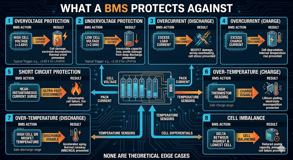
What a BMS Protects Against
These are the specific fault conditions a properly specified BMS defends against:
Cell voltage exceeds max (e.g., >3.65 V for LiFePO4)
Undervoltage protection
Irreversible capacity loss, anode damage from deep discharge
Cell voltage drops below min (e.g., <2.50 V for LiFePO4)
Overcurrent (discharge)
MOSFET damage, wiring overheating, cell stress
Load current exceeds rated maximum
Overcurrent (charge)
Cell degradation, internal temperature rise
Charge current exceeds rated maximum
Short circuit protection
Catastrophic cell failure, fire
Near-instantaneous current surge within microseconds
Over-temperature (charge)
Lithium plating, electrolyte decomposition
Thermistor readings outside safe charge range
Over-temperature (discharge)
Accelerated aging, potential thermal runaway in NMC/NCA
Cell or MOSFET temperatures exceed safe limits
Cell imbalance
Reduced usable capacity, premature cell failure
Delta between highest and lowest cell voltage exceeds threshold
Each of these is a failure mode that real batteries encounter in the field. None are theoretical edge cases.
What Happens Without a BMS
Some installers in price-sensitive markets skip the BMS entirely or use grossly undersized ones to cut system cost. This is one of the most consequential mistakes in energy storage.
Without a BMS, there is no mechanism to stop a charger that pushes too much voltage, no mechanism to prevent a load from draining cells below their minimum threshold, and no balancing circuit to correct the cell divergence that accumulates over hundreds of cycles.
Here is a realistic failure sequence for an unprotected LiFePO4 pack:
Installer wires the pack directly to a lead-acid-configured inverter with a charge voltage set to 58V. Pack maximum charge voltage is 58.4V, but with no BMS to enforce per-cell limits, the highest cells in the string reach 3.75V while the pack terminal reads normal.
The two weakest cells the ones with slightly higher self-discharge are chronically undercharged because the stronger cells hit voltage limits first and the charger terminates. Within six months, those two cells have a 20% capacity deficit relative to the rest.
During discharge, those two weak cells hit the undervoltage threshold first, but with no BMS to disconnect, the pack continues discharging. The weak cells are driven to 1.8V. This is irreversible damage.
On the next charge cycle, the two weak cells barely accept charge. The pack effectively has 14 functional cells and 2 severely degraded ones. The entire pack’s usable capacity is now limited by the weakest link.
The BMS does not just protect you from catastrophic events. It prevents the slow-accumulation failures that destroy packs over time the ones that never produce a single dramatic fault event but silently reduce your battery's usable life by 40–60%.
BMS Specifications That Actually Matter
When evaluating a BMS for a solar storage application, these are the parameters that determine whether it is adequate:
Continuous Discharge Current Rating
Must be equal to or greater than your inverter’s maximum input current. For a 5kVA inverter on a 48V system drawing up to 100A DC, your BMS must be rated for at least 100A continuous with meaningful derating margin for temperature.
Cell Count Compatibility
The BMS must match your cell configuration. A 16S BMS is required for a 16-cell series LiFePO4 pack. Using a 15S BMS on a 16S pack leaves one cell completely unmonitored.
Balancing Current
Higher is generally better. A BMS with 200mA balancing current will take far longer to correct a 5% SOC imbalance than one with 1A or 2A active balancing capability. For large-capacity packs (200Ah and above), low balancing current means corrections cannot keep up with daily cycling rates.
Communication Protocol Support
Must match your inverter. Connecting a BMS that speaks CAN to an inverter expecting RS485 Modbus requires a protocol converter or your BMS data never reaches the inverter at all, and the inverter operates on its own internal voltage-based estimates. Our full guide on inverter-battery communication protocols covers how to verify protocol compatibility before purchase.
Protection Thresholds
Should be configurable, not fixed. Fixed-threshold BMS units cannot be tuned to different cell chemistries or adjusted as cells age. For LiFePO4 packs specifically, the overvoltage trip threshold must be set correctly too low causes premature tripping during normal charging; too high provides no real protection.
Short Circuit Response Time
Should be under 200 microseconds. Slow short-circuit response allows large current pulses to reach the cells before the protection activates.
Smart BMS vs Standard BMS
The battery management market has bifurcated into standard BMS units (protection-only, no communication) and smart BMS units (full communication, monitoring, and app integration).
For a serious solar storage system, a smart BMS is not a luxury. It is the minimum viable specification.
A standard BMS connected to a hybrid inverter gives the inverter no information about the battery’s actual state. The inverter infers SOC from pack voltage a notoriously inaccurate method for LiFePO4 because its discharge voltage curve is extremely flat. The pack can sit at 50% SOC while showing the same terminal voltage as an 80% charged pack.
A smart BMS sends accurate SOC data directly to the inverter via CAN or RS485. The inverter trusts that data and makes better charge/discharge decisions, which means your battery gets used more efficiently and wears more evenly.
Bluetooth and app control standard features on most smart BMS units allow real-time monitoring of individual cell voltages, pack temperature, balance status, and historical cycle data from a mobile device. In field service scenarios, this is enormously useful: a technician can diagnose a weak cell without disconnecting anything.
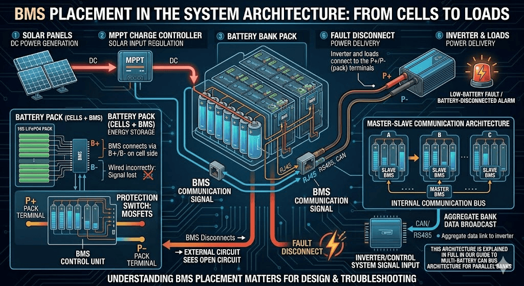
BMS Placement in the System Architecture
Understanding where the BMS sits in the overall system matters for both design and troubleshooting.
In a typical 48V off-grid solar system, the power flow is:
Solar panels generate DC power
MPPT charge controller regulates solar input
Battery pack (cells + BMS) stores energy
BMS connects via B+/B- terminals on the cell side and P+/P- terminals on the load side
Inverter and loads connect to the P+/P- (pack) terminals
When the BMS disconnects due to a fault, the external circuit sees an open circuit. The inverter responds with a low-battery fault or battery-disconnected alarm.
One critical design point: the BMS communication cable runs separately from the power cables. In a Pylontech or BYD battery bank, the RJ45 or RS485/CAN cable carries the BMS data signal to the inverter. Wiring this incorrectly or not at all results in a battery that works electrically but communicates nothing to the inverter.
For multi-battery systems, communication becomes more complex. A master-slave structure is required where one BMS broadcasts aggregate data to the inverter on behalf of the bank. This architecture is explained in full in our guide to multi-battery CAN bus architecture for parallel banks.
Common Installer Mistakes Around BMS Configuration
MISTAKE 1
Setting inverter charge parameters without referencing BMS limits. If the BMS overvoltage protection is set to 3.60V per cell (57.6V for a 16S pack) but the inverter charges to 58.4V, the BMS trips repeatedly during normal charging. Installers then disable the BMS or replace it with a higher-threshold unit. This is dangerous.
MISTAKE 2
Ignoring balancing time during initial commissioning. A new pack assembled from unbalanced cells will show significant cell voltage variance for the first several cycles. Some installers see BMS alarms during early use and assume the BMS is defective. In reality, the cells just need time and balancing current to equalise. Disabling protections to rush this process is how good cells get damaged in their first month.
MISTAKE 3
Not establishing a communication link between BMS and inverter. This is possibly the most common serious mistake in the Nigerian solar installation market. Power cables connected correctly, communication cable unconnected. The system runs, but the inverter has no real-time battery data. You lose SOC accuracy, the ability to respond to BMS fault signals, and the dynamic current limiting that protects cells during edge conditions.
MISTAKE 4
Undersizing the BMS for the actual load. A 100A BMS on a system where the inverter can draw 120A under full load will either trip repeatedly under heavy loads or run its MOSFETs in a thermal stress zone that accelerates their degradation. Always size the BMS with at least 25% current margin above maximum expected load current.
For guidance on full system sizing, our 48V lithium battery sizing guide covers the battery-to-inverter matching calculation in full.
The BMS and Lithium Battery Lifespan
The long-term relationship between BMS quality and battery lifespan is not linear it is multiplicative.
A high-quality cell in a mediocre BMS will underperform its rated cycle life, because the BMS allows marginal conditions on every cycle. A mediocre cell in an excellent BMS will often outperform its specification, because the BMS enforces the optimal operating window consistently.
LiFePO4 cells have a rated cycle life of 3,000 to 6,000 cycles at standard conditions (25°C, 80% DoD, 0.5C rate). In Nigerian field conditions elevated ambient temperatures, variable load profiles, daily deep cycling that cycle life drops significantly without active BMS management.
The specific factors the BMS controls that directly affect cycle life:
Depth of discharge: Cells cycled to 100% DoD lose capacity faster than cells cycled to 80% DoD. A BMS with conservative discharge cutoffs extends calendar life. Our article on the 80/20 rule for lithium batteries explains why this specific operating range matters.
Charge rate near top of charge: High charge current in the final 10% of SOC (above 90%) accelerates electrolyte oxidation. A BMS enforcing CC/CV charging and reducing current near the charge termination voltage protects this sensitive zone.
Temperature during charge: Charging at high temperature or at sub-zero temperatures causes the most severe irreversible capacity loss. The BMS temperature cutoff is the only automatic protection against this.
Balancing quality: Cells that are chronically out of balance operate at the extremes of their voltage range on every cycle. The BMS balancing circuit determines how tightly cells track each other over time.
For a comprehensive framework on extending battery lifespan through system design and operational practices, see our full guide: How to Increase Lithium Battery Lifespan.
BMS Functions: Quick Reference
BMS Function
What It Does
Why It Matters
Cell voltage monitoring
Reads each cell individually
Catches imbalance and overvoltage invisible at pack level
Current monitoring
Measures charge/discharge current
Enables SOC calculation and current limit enforcement
Temperature monitoring
Tracks cell and MOSFET temperatures
Prevents thermally-induced degradation and runaway
Overvoltage protection
Disconnects at high cell voltage
Prevents cell damage from overcharging
Undervoltage protection
Disconnects at low cell voltage
Prevents irreversible deep discharge damage
Overcurrent protection
Limits current in both directions
Protects cells, MOSFETs, and wiring
Short circuit protection
Reacts in microseconds
Prevents catastrophic failure events
Passive/Active balancing
Equalizes cell SOC
Maintains pack capacity and extends cell life
SOC estimation
Tracks remaining capacity
Enables accurate display and inverter decisions
SOH tracking
Monitors capacity fade over time
Predicts maintenance needs
CAN/RS485 communication
Sends data to inverter/monitor
Enables intelligent system-level decisions
Dynamic limits (CVL/CCL/DCL)
Broadcasts real-time operating limits
Prevents edge-condition damage
Why BMS Failures Are Often Misdiagnosed as Battery Failures
One of the most expensive misconceptions in the field: when a lithium battery pack stops working properly, the first thing people blame is the cells.
In the majority of field failures seen in off-grid solar systems, the root cause is not cell failure. It is BMS failure a BMS that was incorrectly specified, incorrectly configured, or that operated outside its thermal rating long enough that its MOSFETs or cell-monitoring ICs degraded.
Symptoms that are often misdiagnosed as bad cells but are actually BMS failures:
Pack shows low SOC but cells test individually at normal voltages BMS SOC calibration error or current sensor drift.
Pack disconnects under load even at 50% SOC MOSFET degradation or overcurrent threshold misconfiguration.
Battery charges to 80% and stops without error BMS charge cutoff misconfigured, or charge MOSFET partial failure.
One cell reads abnormally high or low on the BMS app faulty cell sense wire or damaged balancing circuit on that channel.
Before condemning a battery pack, always connect to the BMS via Bluetooth app or RS485 readout and pull the individual cell voltages, fault history, and temperature logs. The BMS contains the full story of what happened to the pack. In most cases, the cells are fine — the management system failed them.
A BMS monitors individual cell voltages, current, and temperature. It protects cells from overvoltage, undervoltage, overcurrent, short circuit, and overtemperature by disconnecting the pack when any parameter exceeds its safe limit. It also balances cells and communicates real-time data to inverters.
Q: Does every lithium battery need a BMS?
Yes. Every lithium pack LiFePO4, NMC, or NCA requires a BMS. Without one there is no protection against overcharge, deep discharge, overcurrent, or cell imbalance. Some packs (e.g., Pylontech) have the BMS built in; DIY packs require an external BMS.
Q: Can a lithium battery work without a BMS?
Electrically yes it will charge and discharge. But without protection or balancing, cell imbalance grows, weak cells are chronically over/undercharged, and capacity degrades rapidly. NMC and NCA cells can enter thermal runaway without a BMS.
Q: What is the difference between a BMS and a battery charger?
A charger supplies voltage and current to reach the target SOC. A BMS manages internal safety and pack state. The charger controls what enters from outside; the BMS controls whether the pack accepts it. Both are required and must be matched correctly.
Q: How do I know if my BMS is working?
Connect via Bluetooth app or RS485/CAN readout tool. A healthy BMS shows individual cell voltages in a tight range, accurate temperatures, current matching actual load, and SOC tracking that correlates with pack behavior.
Q: What happens when a BMS trips?
The BMS opens its MOSFETs, breaking the circuit. The inverter sees an open circuit and triggers a low-battery or disconnected fault. The BMS stays open until the fault condition clears automatically (e.g., temperature normalising) or manually (e.g., removing the overcurrent condition).
Q: What does SOC mean on a BMS?
State of Charge the current energy level as a percentage of total capacity. 100% = fully charged. A well-configured system never reaches 0% in normal operation; the BMS disconnects before cells reach a damaging depth of discharge.
Q: How do I connect my BMS to my inverter?
Match the BMS communication protocol (CAN or RS485) to the inverter’s supported protocol. Connect the cable, then configure the inverter’s battery communication setting to the correct protocol and battery brand. Physical connection alone is not enough.
Q: What is the best BMS for a 48V LiFePO4 solar battery?
It depends on cell count, inverter protocol, and current requirements. In Nigeria and West Africa, JK BMS active balancer series and Daly smart BMS are widely deployed. For Victron or Pylontech ecosystems, the manufacturer-embedded BMS is purpose-engineered for those inverters.
Q: Can I use a lead-acid BMS with a lithium battery?
No. Lithium batteries require a lithium-specific BMS with protection thresholds calibrated for lithium chemistry. Using lead-acid charging without a lithium BMS is one of the most common causes of battery damage in the Nigerian solar market. write this as a question and answer under?
I am Engr. Ubokobong Ekpenyong, a solar specialist and lithium battery systems engineer with over five years of hands-on experience designing, assembling, and commissioning off-grid solar and energy storage systems. My work focuses on lithium battery pack architecture, BMS configuration, and system reliability in off-grid and high-demand environments.
Contains information related to marketing campaigns of the user. These are shared with Google AdWords / Google Ads when the Google Ads and Google Analytics accounts are linked together.
90 days
__utma
ID used to identify users and sessions
2 years after last activity
__utmt
Used to monitor number of Google Analytics server requests
10 minutes
__utmb
Used to distinguish new sessions and visits. This cookie is set when the GA.js javascript library is loaded and there is no existing __utmb cookie. The cookie is updated every time data is sent to the Google Analytics server.
30 minutes after last activity
__utmc
Used only with old Urchin versions of Google Analytics and not with GA.js. Was used to distinguish between new sessions and visits at the end of a session.
End of session (browser)
__utmz
Contains information about the traffic source or campaign that directed user to the website. The cookie is set when the GA.js javascript is loaded and updated when data is sent to the Google Anaytics server
6 months after last activity
__utmv
Contains custom information set by the web developer via the _setCustomVar method in Google Analytics. This cookie is updated every time new data is sent to the Google Analytics server.
2 years after last activity
__utmx
Used to determine whether a user is included in an A / B or Multivariate test.
18 months
_ga
ID used to identify users
2 years
_gali
Used by Google Analytics to determine which links on a page are being clicked
30 seconds
_ga_
ID used to identify users
2 years
_gid
ID used to identify users for 24 hours after last activity
24 hours
_gat
Used to monitor number of Google Analytics server requests when using Google Tag Manager
1 minute
You can find more information in our Cookie Policy and .


")


")


")