Why Lithium Batteries Need a BMS: Overcharge, Cell Imbalance, and Thermal Runaway Explained
Why Lithium Batteries Need a BMS explained in detail: learn how a BMS prevents overcharge, deep discharge, overheating, cell imbalance, and dangerous lithium battery failure in solar energy systems.
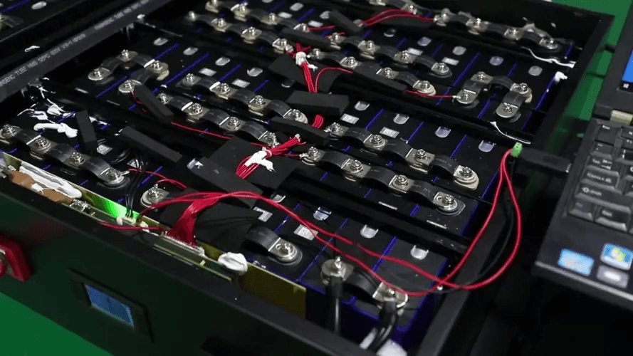
There is a version of this conversation that happens in solar equipment stores across Lagos and Abuja every week.
A customer looks at two battery options: one with a built-in BMS, one without. The one without costs less. The sales assistant says the cells are the same chemistry. The customer chooses the cheaper option.
Eighteen months later, the pack is delivering 40% of its original capacity. By month 24, it is dead.
The failure was not random. It was completely predictable. And it had nothing to do with the quality of the cells. It had everything to do with what was not there to protect them.
This article explains, with engineering precision, exactly why lithium cells require a Battery Management System to function safely and correctly over their rated lifespan. We will cover the specific electrochemical failure modes that a BMS prevents, what happens inside the cells when those failure modes are not intercepted, and what the real-world timeline of a BMS-less battery failure looks like in a solar storage context.
By the end, the BMS will not seem like an optional add-on. It will be exactly what it is: the system that determines whether your lithium investment lasts two years or twelve.
Why Lithium Cells Are Fundamentally Different From Lead-Acid
To understand why a BMS is necessary, you first need to understand what makes lithium cells chemically different from the lead-acid batteries that dominated solar storage for decades.
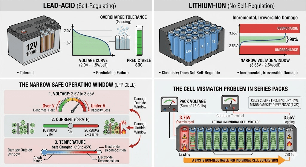
Lead-acid batteries are comparatively forgiving. They tolerate overcharge through a controlled gassing process. They signal their state through a predictable voltage curve that changes significantly with state of charge. They fail slowly, giving warning signs before complete failure. And critically, the chemistry itself provides a degree of self-regulation at the charge endpoint.
Lithium cells operate on fundamentally different electrochemistry, and that chemistry does not self-regulate.
The Narrow Safe Operating Window
Every lithium cell has a safe operating area defined by three parameters: voltage, current, and temperature. Outside this area, the electrochemical reactions that normally store and release energy cleanly instead trigger side reactions that damage or destroy cell components.
For a LiFePO4 cell, the voltage window is 2.5V to 3.65V per cell. That is a 1.15V range. For NMC, it is 3.0V to 4.2V per cell. A 1.2V range. These windows sound generous in isolation, but in a series-connected pack of 16 cells, individual cell voltages can diverge significantly even when the pack terminal voltage appears normal.
The current window is defined by the cell’s rated C-rate. A 100Ah cell rated at 1C can handle 100A continuously. Push it to 2C for extended periods and the electrochemical kinetics cannot keep up: lithium ions pile up faster than the electrode structure can accommodate them, generating heat and causing side reactions that damage the cell structure.
The temperature window is the most situationally variable. Charging above 45 to 55 degC accelerates electrolyte decomposition. Charging below 0 degC causes lithium plating on the anode. Both are outside the safe window, and neither condition announces itself without a monitoring system.
The lead-acid battery tolerates being pushed outside its optimal window. The lithium cell does not. It responds to excursions outside safe parameters with chemistry that works against it, quietly, incrementally, and irreversibly.
The architecture of how these parameters interact inside the cell is covered in full in our Lithium Battery Architecture Handbook. It is the reference document for understanding why the operating window matters at a molecular level.
The Cell Mismatch Problem: Why Series Packs Need Individual Supervision
A single lithium cell is relatively straightforward to manage. Connect it to a charger with the right voltage limit and a suitable current limit, and it will charge correctly.
A series-connected pack of 16 cells is a fundamentally different problem.
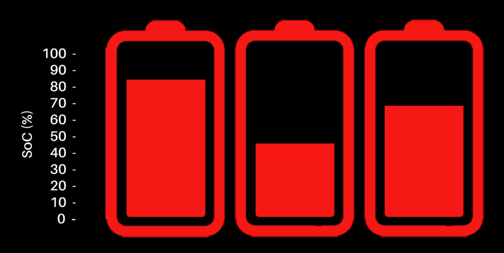
When 16 cells are connected in series, the pack voltage is the sum of all 16 individual cell voltages. The pack terminal voltage is what the charger sees and responds to. But each cell inside that pack has its own voltage, its own state of charge, its own capacity, and its own self-discharge rate.
Cells come from the factory with small variations. Even cells from the same production batch, tested to tight specifications, will have capacity differences of 1 to 3%. Those differences compound over cycles. A cell with 2% lower capacity fills up faster than its neighbours on each charge cycle and empties faster on each discharge cycle. Over 100 cycles, that small difference has become a large one.
Without per-cell monitoring, there is no way to know which cell is leading or lagging. The charger sees only the pack terminal voltage and terminates charging when the pack reaches its target voltage. But the leading cell may already be at 3.75V while the others are at 3.55V. Without a BMS watching individual cells, that overcharged leading cell receives no protection.
This is the core problem that makes individual cell supervision non-negotiable for lithium packs of any practical size. It is not enough to monitor the pack as a whole. Every cell must be monitored individually.
Every Failure Mode a BMS Prevents: Complete Technical Reference
The following table documents every major electrochemical failure mode that a BMS protects against. Each entry includes the root cause mechanism at the cell level, the trigger condition, and the outcome if unprotected.
Failure Mode
Root Cause Mechanism
Trigger Condition
Outcome Without BMS Protection
Overcharge (overvoltage)
Electrolyte oxidation, gas generation inside cell, separator breakdown, thermal runaway in NMC/NCA
Cell voltage exceeds chemistry maximum (e.g., >3.65V for LiFePO4, >4.25V for NMC)
Permanent capacity loss, cell swelling, potential fire
Deep discharge (undervoltage)
Copper dissolution from anode current collector, structural damage to cathode material
Cell voltage drops below chemistry minimum (e.g., <2.5V for LiFePO4, <3.0V for NMC)
Permanent capacity loss, internal short circuit risk on recharge
Accelerated SEI layer growth, electrolyte degradation
Cell temperature above safe discharge limit (typically >60 degC)
Accelerated aging, thermal runaway in extreme cases
ENGINEERING NOTE
These are not hypothetical failure scenarios. Every entry in this table represents a documented failure mode with well-characterised electrochemical mechanisms. The research base for lithium battery failure modes is extensive, covering decades of work across consumer electronics, automotive, and stationary storage applications. In the solar storage field in Nigeria and West Africa, most of these failure modes have been observed directly in field-installed systems.
Overcharge:
Overcharge is the most consequential failure mode for lithium batteries, and understanding its mechanisms at the electrochemical level explains why the BMS was designed around voltage monitoring as its primary function.
What Happens Inside a Cell During Overcharge
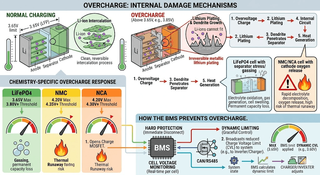
During normal charging, lithium ions move from the cathode material, travel through the electrolyte, and intercalate (insert) into the graphite anode structure. This process is clean, reversible, and stable within the rated voltage window.
When a cell is pushed above its maximum charge voltage, the intercalation process at the anode completes: no more sites are available to accept lithium ions. But the charger continues to push current. The lithium ions that cannot enter the anode structure instead plate onto its surface as metallic lithium. This is lithium plating, and it is irreversible.
Metallic lithium on the anode surface forms dendrites: thin, needle-like projections that grow with each subsequent charge cycle. As dendrites grow longer, they eventually penetrate the separator that divides anode from cathode. When a dendrite bridges the separator, it creates an internal short circuit. The cell discharges internally and rapidly, generating heat. In NMC and NCA chemistries, this heat triggers oxygen release from the cathode, which then reacts with the electrolyte in an exothermic chain reaction. This is thermal runaway.
In LiFePO4, the iron-phosphate cathode does not release oxygen under thermal stress, which is why LiFePO4 does not typically produce thermal runaway. But even without thermal runaway, overcharge in LiFePO4 causes electrolyte oxidation at the positive electrode, gas generation inside the cell, and separator stress from the gassing pressure. The result is permanent capacity loss and reduced cycle life.
Chemistry
Max Charge Voltage (per cell)
Overvoltage Damage Threshold
Damage Mechanism
LiFePO4
3.65V
3.80-4.00V
Electrolyte oxidation, gas generation, separator stress, cell swelling. No thermal runaway but permanent capacity loss.
NMC
4.20V
4.35-4.50V
Rapid electrolyte decomposition, oxygen release from cathode, separator shrinkage, high risk of thermal runaway above 4.35V.
NCA
4.20V
4.30-4.40V
Similar to NMC but more sensitive. Thermal runaway risk begins at lower overvoltage than NMC. One of the most dangerous overcharge scenarios in lithium chemistry.
How the BMS Prevents Overcharge
The BMS monitors each cell’s voltage in real time using a dedicated cell-monitoring IC. When any cell reaches its maximum charge voltage threshold, the BMS takes one or both of the following actions:
It opens the charge MOSFET switch, cutting the charge path entirely. This is the hard protection response.
It broadcasts a reduced Charge Voltage Limit (CVL) via CAN or RS485 to the inverter or charge controller, directing the system to reduce charging current. This is the dynamic limit response, which allows charging to continue at a safe rate without triggering a full disconnect.
The combination of hard protection and dynamic limit broadcasting allows the BMS to manage the charge endpoint gracefully in most conditions, only triggering a hard disconnect when the dynamic limit approach has not been sufficient to prevent a cell from reaching its maximum voltage.
The dynamic limit system: CVL, CCL, and DCL, is explained in engineering detail in our article on understanding dynamic battery limits in real time. This is one of the most underappreciated functions in the entire BMS architecture.
Deep Discharge:
If overcharge is the failure mode most people know about, deep discharge is the one that actually kills more packs in real-world solar storage applications. It is slower, quieter, and typically well advanced before anyone notices.
What Happens Inside a Cell During Deep Discharge
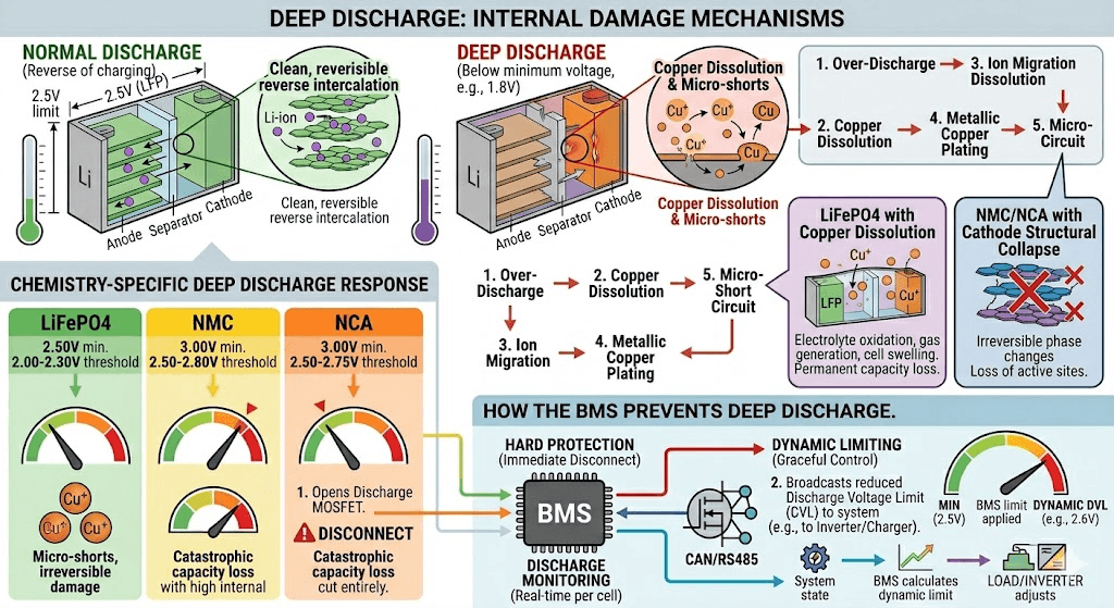
During normal discharge, lithium ions move from the graphite anode, travel through the electrolyte, and re-intercalate into the cathode structure. This is the reverse of charging and is equally clean and reversible within the rated discharge window.
When a cell is discharged below its minimum voltage, the lithium inventory in the anode is exhausted. With no more lithium ions available from the graphite structure, the electrode begins to oxidise. In the process, copper from the copper current collector beneath the graphite begins to dissolve into the electrolyte as copper ions.
These copper ions migrate through the electrolyte and can deposit as metallic copper on the other electrode. Metallic copper deposits inside a cell create permanent internal short circuit paths. Unlike lithium dendrites, which form and can theoretically dissolve, copper deposits are stable and permanent. A cell that has been deep-discharged to the point of copper dissolution has sustained irreversible structural damage.
Even before copper dissolution becomes significant, the cathode structure in NMC and NCA batteries suffers irreversible phase changes below the minimum voltage threshold. Lithium sites in the cathode lattice that are permanently vacated below certain voltage levels do not recover when the cell is recharged. The capacity is simply gone.
Chemistry
Minimum Discharge Voltage (per cell)
Critical Damage Threshold
Damage Mechanism
LiFePO4
2.50V
2.00-2.30V
Copper dissolution from current collector. Copper ions migrate and can deposit as metallic copper inside the cell, causing micro-short circuits. Irreversible.
NMC
3.00V
2.50-2.80V
Structural collapse of cathode material. Loss of lithium sites. Severe and irreversible capacity loss. High internal resistance increase.
NCA
3.00V
2.50-2.75V
Similar to NMC. Nickel-rich cathodes are particularly sensitive to deep discharge. Capacity loss is rapid and irreversible below the minimum threshold.
The Series Pack Problem and Deep Discharge
In a series pack, deep discharge is particularly insidious because it affects individual cells asymmetrically.
Consider a 16S LiFePO4 pack with one weak cell: a cell that has 10% less capacity than the other 15. During discharge, that weak cell empties first. When it reaches 2.5V (the BMS minimum), the pack terminal voltage is still above 40V, which looks normal to the inverter. Without a BMS performing per-cell monitoring, the inverter continues to draw current, pushing the weak cell below 2.5V, then below 2.0V, then below 1.5V.
The other 15 cells are completely unaffected. They are still at safe voltages. But the one weak cell has been deep-discharged past its damage threshold on every cycle since it began falling behind. The damage compounds with each cycle.
After enough cycles, the weak cell has near-zero effective capacity and high internal resistance. Now, every charge cycle, the current flowing through the pack heats that high-resistance cell disproportionately. The thermal stress accelerates its degradation further. Within months, it can no longer participate meaningfully in charge or discharge cycles at all.
The entire pack is now limited by the capacity of one dead cell. The other 15 cells may be in perfect condition, but the pack delivers a fraction of its rated capacity.
Cell imbalance is not a single dramatic event. It is a continuous, gradual divergence between cells that compounds over time and eventually reduces the usable capacity of the entire pack to the level of the weakest cell.
The Mechanics of Cell Divergence
Every cell in a series pack has three parameters that affect how it behaves relative to its neighbours:
Actual capacity: The total energy it can store, in Ah. Cells from the same production batch may differ by 1 to 5%.
Internal resistance: The opposition to current flow inside the cell. Higher internal resistance means more voltage drop under load and more heating. Cells age at different rates, causing resistance to diverge over time.
Self-discharge rate: The rate at which a cell loses charge when not in use. Slightly higher self-discharge in one cell means it enters each charge cycle at a lower SOC than its neighbours.
These three parameters interact. A cell with slightly lower capacity fills up faster on each charge cycle. If the pack is charged to a fixed terminal voltage without per-cell balancing, the lower-capacity cell hits the charge voltage limit first while the other cells are still not fully charged. The charger terminates because the pack terminal voltage has reached target, but the other cells are only at, say, 95% SOC.
On discharge, the same lower-capacity cell depletes first. If the pack is discharged to a fixed terminal voltage without per-cell monitoring, this cell hits its minimum voltage while the other cells still have 15 to 20% capacity remaining. The pack disconnects with unused capacity left in the stronger cells.
The result: the pack’s usable capacity is bounded above and below by the weakest cell. As the weak cell degrades further under the stress of being at the extremes of its voltage range on every cycle, the capacity loss compounds. Without a BMS to balance cells and protect the weak ones, this is an accelerating downward spiral.
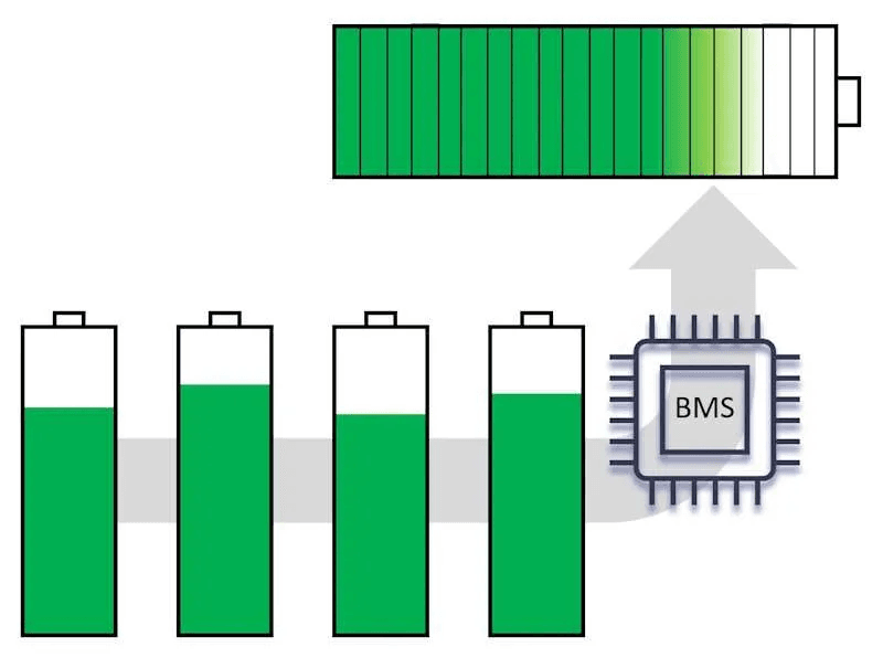
What the BMS Does About Cell Imbalance
The BMS balancing circuit addresses cell divergence through one of two mechanisms:
Passive balancing: Resistors connected in parallel with each cell are switched on when that cell’s voltage is above the pack average. The resistor bleeds off energy as heat, reducing the high cell’s voltage until it matches the lower cells. Simple and inexpensive, but slow and wasteful. Balancing current in passive systems is typically 30 to 200mA.
Active balancing: Energy is transferred from higher-voltage cells to lower-voltage cells using inductive or capacitive circuits. Nothing is wasted as heat; the energy is redistributed within the pack. Active balancing currents can reach 1 to 5A, making correction of large imbalances practical within a single charge cycle.
For solar storage systems with large daily cycling and significant capacity, the difference between passive and active balancing is substantial. We examined the specific failure patterns that passive balancing creates in high-discharge solar systems in our analysis: Why Passive Balancing BMS Fails in High-Discharge Solar Battery Systems.
Unlike overcharge and deep discharge, which operate on timescales of months, overcurrent and short circuit are rapid failure modes. The damage can occur in seconds or milliseconds.
Overcurrent During Discharge
Every lithium cell has a rated maximum discharge current, expressed as a C-rate. A 100Ah cell rated at 1C can deliver 100A. At 2C, it delivers 200A but with greater internal heating and faster degradation. Above the rated maximum, the electrochemical kinetics at the electrode interfaces cannot keep pace with the demanded current.
When current exceeds the safe limit, several things happen simultaneously. The cell’s internal resistance generates heat proportional to I-squared times R. Voltage drops rapidly. The electrolyte cannot transport lithium ions fast enough to sustain the demand, leading to localised lithium depletion near the electrode surface. These electrochemical stress conditions accelerate the growth of the Solid Electrolyte Interphase (SEI) layer on the anode, permanently reducing capacity and increasing internal resistance.
In the wiring and MOSFET switches of the BMS, sustained overcurrent causes thermal stress proportional to I-squared times R. Undersized wiring can overheat. MOSFET junctions run above their thermal rating. Over time, MOSFET performance degrades and eventually fails.
The BMS overcurrent protection monitors discharge current through a shunt resistor or Hall-effect sensor. When the measured current exceeds the set threshold, the BMS opens the discharge MOSFET within milliseconds to protect both the cells and the circuit components.
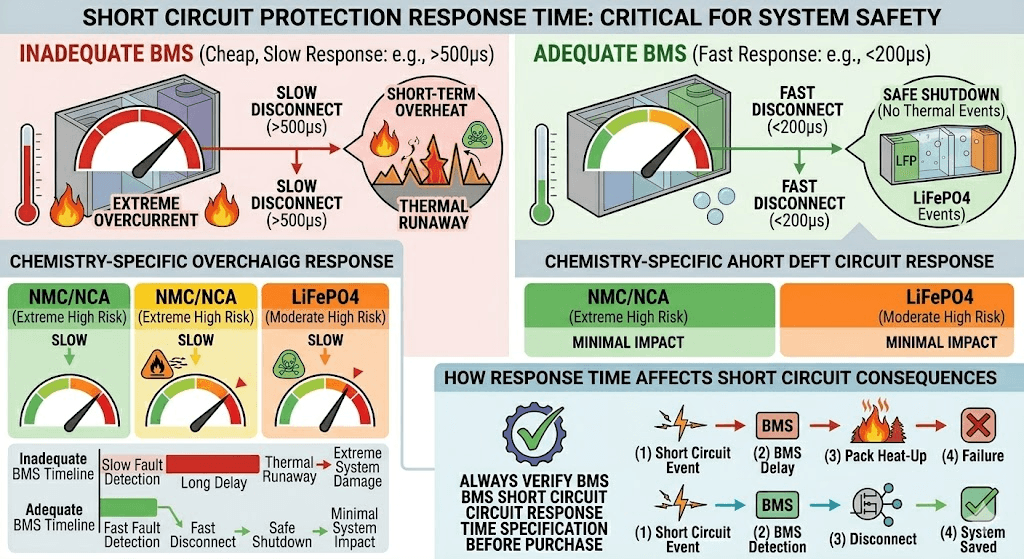
Short Circuit: The Extreme Case
A direct short circuit across the battery terminals creates a near-zero-resistance path for current flow. Ohm’s law is unforgiving: with very low resistance and full pack voltage, the current can reach thousands of amps in milliseconds.
At those current levels, cell temperatures rise explosively fast. Electrolyte vaporises. Internal pressure spikes. In NMC and NCA cells, the thermal gradient is sufficient to trigger cathode oxygen release and thermal runaway.
The BMS short circuit protection uses a dedicated fast-response comparator circuit that monitors current with microsecond resolution. When a current spike consistent with a short circuit is detected (typically a current several times the overcurrent threshold within microseconds), the BMS fires its MOSFET switches off in under 200 microseconds, before the cell temperature has time to rise significantly.
This is the fastest response path in the entire BMS. It is the last line of defence between a wiring error or faulty load and a battery fire.
SAFETY WARNING
Short circuit protection response time is a critical BMS specification. Cheap BMS units with slow response times (>500 microseconds) provide inadequate short circuit protection. In NMC and NCA systems especially, the consequences of slow short circuit protection are severe. Always verify the short circuit response time specification before purchasing a BMS for any system carrying significant energy.
Temperature:
Temperature is the BMS protection parameter most frequently underweighted in system design, and most frequently responsible for premature battery failure in West African field conditions.
Lithium cell chemistry is temperature-dependent at a fundamental level. The speed of electrochemical reactions, the conductivity of the electrolyte, the stability of the SEI layer, and the physical expansion and contraction of electrode materials all change with temperature. The safe operating window for lithium cells in both charge and discharge directions is bounded by temperature as strictly as it is by voltage.
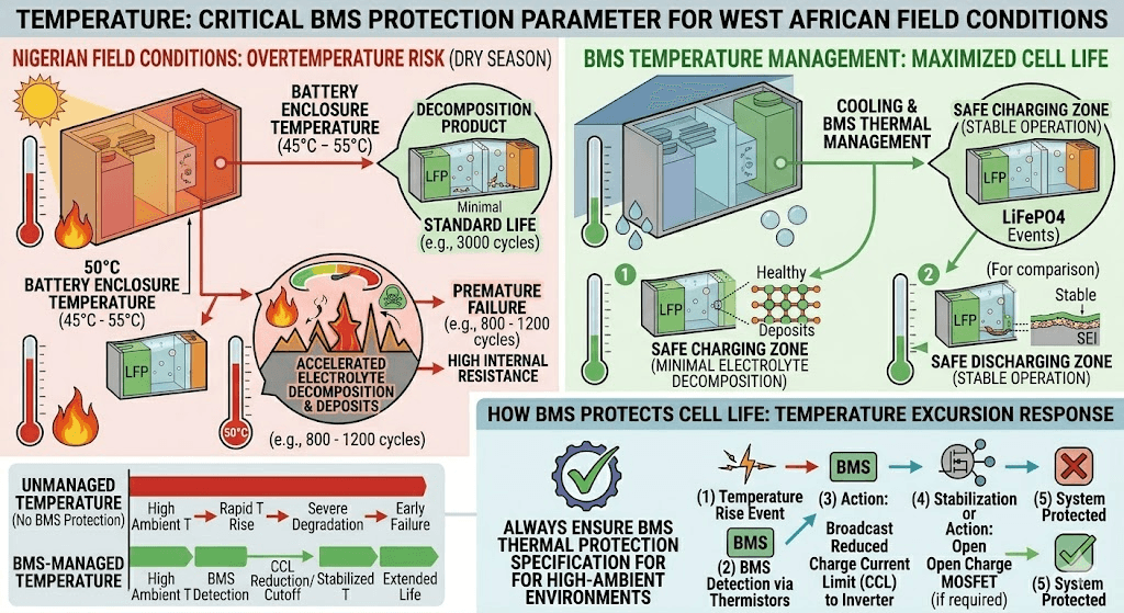
Overtemperature During Charging
Charging at high temperature accelerates the decomposition of the electrolyte solvent. The decomposition products form as deposits on electrode surfaces, consuming lithium and increasing internal resistance. This process is thermally activated: for every 10 degC rise in temperature above the nominal operating point, the degradation rate approximately doubles.
In Nigerian field conditions, battery enclosure temperatures during the dry season can reach 45 to 55 degC. A battery charged at 50 degC is experiencing electrolyte decomposition at a rate many times higher than one charged at 25 degC. Under daily cycling at these temperatures without BMS thermal protection, a LiFePO4 pack rated at 3,000 cycles under standard conditions might deliver 800 to 1,200 cycles before reaching 80% SOH.
Charging at low temperature is equally damaging but for a different reason. Below 0 degC, the rate of lithium ion intercalation into the graphite anode drops sharply. Ions that cannot enter the anode structure plate onto its surface as metallic lithium. As noted in the overcharge section, this lithium plating leads to dendrite growth, and dendrites lead to internal short circuits. Cold temperature charging is one of the most reliable paths to rapid and irreversible capacity loss.
What the BMS Does
The BMS uses thermistors mounted on the cell stack and near the MOSFET switches to monitor temperature continuously. When cell temperatures exceed the safe charging threshold (typically 45 to 55 degC depending on chemistry and configuration), the BMS:
Broadcasts a reduced Charge Current Limit (CCL) to the inverter, instructing it to reduce charging current. Lower current means lower I-squared-R heating inside the cells.
If temperature continues to rise, cuts off charging entirely by opening the charge MOSFET until temperature returns to a safe range.
In cold conditions, the same logic applies in reverse: the BMS reduces or stops charging until the cells have warmed to a safe temperature.
For the Nigerian context, the hot temperature protection is the critical function. Systems installed without BMS thermal management in high-ambient-temperature environments are operating without the one protection mechanism that most directly addresses the specific failure mode that Nigerian conditions amplify.
Beyond Protection:
Everything discussed so far focuses on the BMS as a protection device: something that disconnects circuits when parameters exceed safe limits. This is the most critical function, but it is not the only one.
A modern smart BMS is also a real-time data system that monitors, calculates, stores, and broadcasts information about the battery’s state to the inverter, to monitoring systems, and to maintenance personnel.
SOC Estimation and Communication
The BMS calculates State of Charge using coulomb counting: it integrates the current flowing in and out of the pack over time. This running total, combined with periodic calibration at the charge and discharge endpoints, gives a much more accurate SOC estimate than voltage-based methods.
For LiFePO4 particularly, this matters enormously. The discharge voltage curve of LiFePO4 is nearly flat between 90% and 20% SOC, with only a 50 to 100mV variation across that entire range. An inverter relying on pack voltage to estimate SOC will consistently misread the battery state. It may show 80% SOC when the pack is at 50%, or switch to generator backup at 60% SOC when 40% of capacity is still available.
Communication Protocols: How the BMS Talks to the Inverter
The BMS communicates with the inverter via one of several digital protocols:
CAN bus: Used by Victron, BYD, Pylontech, and most premium battery systems. Differential two-wire protocol, highly noise-immune. Transmits cell voltages, pack voltage, current, temperature, SOC, fault codes, and dynamic limits.
RS485 Modbus: Used by most Chinese inverter brands including Deye, Growatt, and Solis. Point-to-point or multi-drop serial protocol. Carries the same data set as CAN bus but with a different physical layer and framing protocol.
UART: Used for local BMS configuration and Bluetooth module communication on smart BMS units.
When the BMS communication is working correctly, the inverter receives real-time data and can make intelligent decisions: reducing charge current as the pack approaches full, preventing discharge below the BMS-specified minimum, and responding to fault signals by switching energy sources appropriately.
When the communication cable is not connected, as happens frequently in Nigerian solar installations, the inverter is making all of these decisions in the dark, using only the pack terminal voltage as its guide. The gap between what the inverter thinks is happening and what is actually happening inside the cells grows with every cycle.
The following timeline represents the typical failure progression of a LiFePO4 pack installed without a BMS in a standard Nigerian off-grid solar application: 48V, 200Ah nominal, cycling daily to 80% depth of discharge, installed in a non-air-conditioned generator room with typical ambient temperatures of 30 to 45 degC.
Timeline
Observable Symptoms
What Is Actually Happening Inside the Pack
Month 1-3
System appears to function normally. No visible symptoms.
Cell imbalance begins accumulating silently. Weakest cells are being marginally overcharged and undercharged on each cycle.
Month 4-6
Slightly reduced runtime. Inverter may show marginally lower battery percentage for the same load.
Weakest cells now have 10-15% capacity deficit. Each cycle pushes them closer to voltage limits. Balancing cannot catch up without a BMS.
Month 6-12
Noticeable capacity reduction. System struggles to supply full nighttime load. Inverter switches to generator earlier.
Two or three cells are now severely imbalanced. On deep discharges they hit the undervoltage threshold first, but without a BMS there is nothing to stop the discharge. These cells are being deep-discharged to damaging levels nightly.
Month 12-18
System capacity is now 50-60% of original. Daily runtime is severely reduced. Customer complaints escalate.
Severely damaged cells now have very low capacity and high internal resistance. Every charge cycle overheats them slightly. The pack is approaching the point of unpredictable behavior.
Month 18-24
Pack failure. Either complete inability to hold charge, or in NMC/NCA systems, a thermal event triggered by the damaged cells during charging.
Total pack loss. In LiFePO4 this is a financial loss. In NMC or NCA this can be a safety incident.
FIELD OBSERVATION
This failure timeline is not theoretical. It is constructed from the observed failure patterns of BMS-less and inadequately protected battery installations documented in the Nigerian solar market. The timeline compresses further in hotter environments, with higher daily cycling rates, and with lower-quality cells. In the best-case scenario, a pack without proper BMS protection running in Nigerian conditions lasts 12 to 18 months. Most last less.
The Complete BMS Protection Architecture
The following table provides a consolidated reference for every BMS protection function, how it works, and what it prevents. Use this as a specification checklist when evaluating a BMS for a new installation.
BMS Protection Function
How It Works
What It Prevents
Overvoltage protection (OVP)
Disconnects charge path when any cell exceeds max voltage
Prevents electrolyte oxidation, gas generation, and thermal runaway
Undervoltage protection (UVP)
Disconnects discharge path when any cell drops below min voltage
Prevents copper dissolution, cathode damage, and internal short circuit risk
Overcurrent protection (OCP) discharge
Disconnects load when discharge current exceeds rated limit
Protects cells, MOSFETs, wiring, and battery terminals from thermal damage
Overcurrent protection (OCP) charge
Limits or cuts charge current above rated maximum
Prevents lithium plating and dendrite formation
Short circuit protection (SCP)
Opens MOSFETs within microseconds of detecting a current spike
Prevents catastrophic cell failure and fire from terminal short circuit
Overtemperature protection (OTP) charge
Stops or reduces charging when temperature exceeds safe limit
Prevents lithium plating (cold) and electrolyte decomposition (hot) during charging
Overtemperature protection (OTP) discharge
Disconnects or limits discharge above thermal threshold
Prevents accelerated degradation and thermal runaway in worst-case scenarios
Cell balancing
Redistributes charge between cells to equalise SOC
Maintains full usable capacity and prevents chronic over/undercharge of individual cells
SOC estimation and reporting
Tracks and broadcasts real-time state of charge via CAN/RS485
Enables inverter to make accurate charge/discharge decisions
Dynamic limit broadcasting (CVL/CCL/DCL)
Sends real-time operating limits to inverter
Allows inverter to adapt charging to actual battery state, not fixed voltage parameters
What Most Installers Get Wrong About BMS Requirements
MISTAKE 1
Confusing a battery with an integrated BMS for a battery that needs no BMS. Commercial sealed units like Pylontech US3000C have a BMS built in. Raw cells sold for DIY packs do not. Installers who buy EVE or CALB cells without realising they must add an external BMS are effectively installing unprotected cells. The result is the failure timeline described above.
MISTAKE 2
Buying a BMS rated for the wrong current. A 100A BMS on a system that will occasionally demand 110A is not a small mismatch. The BMS will either trip repeatedly under peak loads or will operate its MOSFETs in continuous thermal stress. Always size the BMS at 125% of maximum expected discharge current at minimum.
MISTAKE 3
Not configuring the BMS protection thresholds for the specific cells installed. A BMS shipped from a manufacturer may have default thresholds that are too conservative for one cell type or not conservative enough for another. For LiFePO4, overvoltage protection must be set to 3.65V per cell. For NMC, 4.20V. Using the wrong thresholds either prevents full charging or fails to protect cells at the voltage extremes.
MISTAKE 4
Ignoring BMS fault codes and overriding protection trips. When a BMS trips repeatedly, the correct response is to diagnose and fix the root cause: check individual cell voltages, check temperatures, check wiring for resistance issues, check inverter charge parameters. The worst response is to replace the BMS with a unit that has higher trip thresholds. This removes the protection without addressing the underlying problem.
Not all BMS units provide all the protection functions described in this article. At the low end of the market, a BMS may provide only basic OVP, UVP, and OCP with no communication, no balancing, and no temperature-based protection. At the high end, a smart BMS provides all protection functions, active balancing, full CAN/RS485 communication, SOC and SOH tracking, Bluetooth monitoring, and configurable thresholds for every parameter.
For a solar storage application in Nigeria, the minimum viable BMS specification is:
Per-cell voltage monitoring with configurable OVP and UVP thresholds
Current monitoring with configurable OCP for both charge and discharge
Short circuit protection with response time under 200 microseconds
Temperature monitoring with at least two thermistors and configurable charge and discharge temperature limits
Passive or active cell balancing
Communication interface matching the inverter: CAN or RS485
Current rating at least 125% of maximum expected discharge current
Any BMS that does not meet this specification is providing incomplete protection for a lithium battery installation.
For guidance on which BMS units meet this specification in practice, see our dedicated article on choosing the right BMS for LiFePO4 systems. For inverter compatibility verification, see our guide on BMS-to-inverter communication troubleshooting.
Frequently Asked Questions
Why do lithium batteries need a BMS?
Lithium batteries require a BMS because the electrochemical processes inside lithium cells operate within a narrow safe window of voltage, current, and temperature. Outside that window, the reactions that normally store and release energy cleanly instead trigger side reactions that destroy the cell materials. The BMS continuously monitors conditions inside the pack and intervenes before any parameter crosses a damaging threshold. Without this supervision, lithium cells will inevitably be pushed outside safe limits during normal charge and discharge cycles, particularly as cells age and drift apart in capacity.
What happens if you use a lithium battery without a BMS?
Without a BMS, a lithium battery will operate initially but degrade rapidly. The most immediate problem is cell imbalance: cells with slightly higher self-discharge rates fall behind on each charge cycle while stronger cells are overcharged. Over 6 to 18 months, this divergence compounds. Weak cells are deep-discharged past safe limits on every cycle; strong cells are chronically overcharged. The result is irreversible capacity loss, high internal resistance, and eventual pack failure. In NMC or NCA chemistry, the process can also culminate in a thermal event.
Can you run a LiFePO4 battery without a BMS?
You can charge and discharge a LiFePO4 battery without a BMS, but doing so will dramatically shorten the pack’s life and risks permanent cell damage. LiFePO4 is more tolerant than NMC or NCA, but it still requires protection from deep discharge, overcharge, overcurrent, and cell imbalance. Some DIY builders run LiFePO4 cells briefly without a BMS during testing and initial top-balancing, but this should never be an operational configuration.
What are the dangers of a lithium battery without a BMS?
The primary dangers are: (1) permanent capacity loss from overcharge and deep discharge, (2) internal short circuit formation from copper dissolution or lithium dendrite growth, (3) thermal runaway in NMC and NCA chemistries if overcharge triggers oxygen release from the cathode, and (4) pack failure under high-current fault conditions with no short circuit protection. For LiFePO4 the dominant danger is financial loss from premature pack failure. For NMC and NCA, the danger includes fire and safety incidents.
How does a BMS prevent overcharging?
The BMS monitors the voltage of each individual cell in real time. When any cell reaches its maximum charge voltage (3.65V for LiFePO4, 4.20V for NMC), the BMS opens the charge MOSFET switch, breaking the charge circuit. It also broadcasts a reduced Charge Voltage Limit (CVL) to the inverter via CAN or RS485, signalling the inverter to reduce or stop charging. Both mechanisms together ensure the cells cannot be pushed past their safe upper limit.
How does a BMS prevent deep discharge?
The BMS monitors each cell’s voltage during discharge. When any cell drops to its minimum threshold (typically 2.5 to 2.8V for LiFePO4), the BMS opens the discharge MOSFET, disconnecting the load. This happens on a per-cell basis: if one weak cell in a 16S pack drops to 2.5V while the other 15 are still at 3.0V, the BMS disconnects the entire pack to protect the weak cell. Without this per-cell protection, the pack would continue discharging and the weak cell would be driven into damaging territory.
What is cell imbalance and why does it matter?
Cell imbalance occurs when individual cells in a series pack develop different states of charge due to differences in capacity, internal resistance, and self-discharge rate. In a balanced pack, all cells reach full charge and minimum discharge simultaneously, giving full use of the pack’s total capacity. In an imbalanced pack, the weakest cell limits the entire pack: charging stops early (when the weakest cell hits its max voltage first) and discharging stops early (when the weakest cell hits its min voltage first). The BMS balancing circuit corrects this divergence continuously.
Does a sealed lithium battery like Pylontech already have a BMS?
Yes. Pylontech, BYD, Dyness, and most commercial sealed lithium battery units have an integrated BMS built into the battery enclosure. This BMS handles all protection functions, balancing, and communication. When you connect one of these batteries to a compatible inverter, the integrated BMS communicates via CAN or RS485. You do not need an external BMS for sealed commercial units. External BMS units are needed when building battery packs from raw cells, as in DIY configurations.
What is the difference between a BMS protection trip and a battery fault?
A BMS protection trip is a normal, deliberate response to a parameter exceeding a safe threshold. The BMS disconnects the circuit to prevent damage. This is the BMS working correctly. A battery fault is a physical problem inside the cells themselves: a damaged cell, an internal short circuit, or severe capacity loss due to aging or prior damage. Protection trips resolve when the triggering condition is removed. Battery faults persist regardless of what the BMS does. Distinguishing between the two requires reading BMS data: cell voltages, temperature history, and fault logs.
How does the BMS know when a battery is full?
The BMS uses two methods. First, voltage monitoring: when cells reach the charge termination voltage, the BMS signals the end of the charge cycle. Second, current monitoring: in the CV (constant voltage) phase of charging, the BMS watches the current taper. When the current drops below a threshold (typically C/20, meaning 5% of the rated capacity), the BMS considers the pack fully charged and closes the charge circuit. Together these methods ensure the pack is reliably fully charged without being overcharged.
I am Engr. Ubokobong Ekpenyong, a solar specialist and lithium battery systems engineer with over five years of hands-on experience designing, assembling, and commissioning off-grid solar and energy storage systems. My work focuses on lithium battery pack architecture, BMS configuration, and system reliability in off-grid and high-demand environments.
Contains information related to marketing campaigns of the user. These are shared with Google AdWords / Google Ads when the Google Ads and Google Analytics accounts are linked together.
90 days
__utma
ID used to identify users and sessions
2 years after last activity
__utmt
Used to monitor number of Google Analytics server requests
10 minutes
__utmb
Used to distinguish new sessions and visits. This cookie is set when the GA.js javascript library is loaded and there is no existing __utmb cookie. The cookie is updated every time data is sent to the Google Analytics server.
30 minutes after last activity
__utmc
Used only with old Urchin versions of Google Analytics and not with GA.js. Was used to distinguish between new sessions and visits at the end of a session.
End of session (browser)
__utmz
Contains information about the traffic source or campaign that directed user to the website. The cookie is set when the GA.js javascript is loaded and updated when data is sent to the Google Anaytics server
6 months after last activity
__utmv
Contains custom information set by the web developer via the _setCustomVar method in Google Analytics. This cookie is updated every time new data is sent to the Google Analytics server.
2 years after last activity
__utmx
Used to determine whether a user is included in an A / B or Multivariate test.
18 months
_ga
ID used to identify users
2 years
_gali
Used by Google Analytics to determine which links on a page are being clicked
30 seconds
_ga_
ID used to identify users
2 years
_gid
ID used to identify users for 24 hours after last activity
24 hours
_gat
Used to monitor number of Google Analytics server requests when using Google Tag Manager
1 minute
You can find more information in our Cookie Policy and .


")


