Solar Pump Controller Settings: What Each Parameter Does and How to Set Them Correctly
Learn the correct solar pump controller settings for Nigerian boreholes and farm pumps. Configure VFD and DC solar pump controllers properly to prevent dry-run damage, overheating, water hammer, and startup failures.
You have installed a solar pump system. The controller is powered up and showing a menu of parameters. Now what?
Most installers scroll past the parameter list, leave everything at factory defaults, and hope for the best. Sometimes that works. More often it leads to a pump that fails to start on cloudy mornings, a motor that overheats by noon, or a borehole that runs dry and burns out the motor within one dry season.
Every parameter in a solar pump controller exists for a reason. This guide explains what each one does in plain terms, what happens when it is wrong, and gives you the correct settings for Nigerian borehole and farm pump conditions.
This guide covers both solar VFD controllers (for AC pumps) and DC solar pump MPPT controllers (for brushless DC pumps). Where settings differ between controller types, both are addressed.
Before You Touch Any Parameter: What to Check First
Changing parameters on a running pump controller without understanding the current state of the system can cause immediate damage. Before accessing any settings:
Confirm the pump is not running. Power down or wait for the pump to stop before entering parameter mode.
Record all current parameter values before changing anything. Take a photo of each screen. This is your restore point if something goes wrong.
Have the motor nameplate data in hand: rated voltage, rated current (full-load current), rated power in kW, rated frequency, rated RPM, and power factor if available.
Have your borehole depth data available: static water level, pump setting depth, and TDH. Several parameters are set based on these values.
Confirm which controller model you are using. Parameters are numbered differently across brands. Use this guide to understand the function, then find the equivalent parameter number in your specific controller manual.
Never reset the controller to factory defaults on an installed system without first recording all existing parameter values. Factory defaults are designed for generic conditions, not your specific borehole depth, motor size, and Nigerian climate.
Group 1: Power Input Parameters
These parameters define how the controller interacts with the solar array on the input side. Getting these wrong means the controller either refuses to start when it should, or attempts to start when there is insufficient power and damages the motor.
P01: Minimum Start Voltage (DC Input Undervoltage Threshold)
What it does: Sets the minimum DC voltage from the solar array at which the controller will attempt to start the pump motor. If the array voltage is below this value, the controller waits and does not attempt a start.
Why it matters: On a cloudy morning or during heavy harmattan dust, the solar array may produce voltage but not enough power to start and run the motor. If the controller starts the motor on insufficient power, the motor draws more current than the array can supply, the voltage collapses, and the motor stalls. Repeated stalling heats the motor windings and can cause permanent damage.
Array Configuration
Open Circuit Voltage (Voc)
Correct P01 Setting
2 x 400W panels in series (800W, 24V nominal)
Approx 50V Voc
35 to 38V (70-75% of Voc)
4 x 400W panels in series (1,600W, 48V nominal)
Approx 100V Voc
70 to 75V
6 x 400W panels (2 series x 3 parallel)
Approx 100V Voc
70 to 75V
8 x 400W panels (2 strings of 4 in series)
Approx 200V Voc
140 to 150V
12 x 400W panels (3 strings of 4 in series)
Approx 200V Voc
140 to 150V
Correct P01 setting: 70 to 75 per cent of your array's open-circuit voltage (Voc). This ensures there is adequate power available before the start is attempted.
P02: Maximum Input Voltage (Overvoltage Protection Threshold)
What it does: Sets the maximum DC voltage the controller will accept from the solar array. If voltage exceeds this threshold, the controller disconnects to protect its internal components.
Why it matters: On a cold, clear harmattan morning with no cloud cover, solar panels produce their highest voltage (cold panels have higher Voc than hot panels). If this peak voltage exceeds the controller’s rated maximum input voltage, the IGBT transistors or capacitors can be destroyed instantly.
Correct setting: This is factory-set based on the controller’s rated maximum input voltage. Do not increase it. The important action here is to verify your array’s maximum possible Voc does not exceed the controller’s input rating. The maximum panel Voc occurs at coldest expected temperature.
In northern Nigeria where temperatures can drop to 10 to 15 degrees Celsius in December and January, a 400W panel with a standard temperature coefficient will produce approximately 5 to 8 per cent higher Voc than at 25 degrees STC. Account for this when selecting your controller.
P03: MPPT Voltage Range (Minimum and Maximum MPPT Tracking Voltage)
What it does: Defines the voltage window within which the MPPT algorithm will search for the Maximum Power Point. The controller sweeps through this range to find the voltage at which the panel produces maximum power.
Why it matters: If the MPPT range is set too narrow, the controller may miss the actual MPP during morning ramp-up or during cloudy periods when the MPP shifts to a lower voltage. If it is set too wide, the MPPT sweep takes longer and wastes power during the search.
Correct setting: The MPPT range should span from approximately 60 per cent to 95 per cent of Voc. For most controllers this is a factory-calibrated range based on the input voltage rating. Check that your array’s Vmpp at operating temperature falls within this window.
For a full explanation of how MPPT tracking works and how to verify your array is operating at its maximum power point, see: MPPT Charge Controller Selection Guide.
Group 2: Motor Control Parameters
These parameters define how the controller drives the motor. They are the settings that most directly affect motor longevity and daily pumping performance. Most motor failures in Nigerian installations trace back to wrong settings in this group.
P10: Motor Rated Power (kW)
What it does: Tells the controller the rated output power of the motor it is driving. The controller uses this value to calculate internal protection thresholds and current limits.
Why it matters: If this value is set lower than the actual motor power, the controller will trip on overcurrent at normal motor load. If set higher than actual, the controller will allow the motor to draw more current than it is rated for, causing overheating.
Correct setting: Read the motor nameplate. Enter the exact rated power in kW. A 1 HP motor is 0.75 kW. A 1.5 HP motor is 1.1 kW. A 2 HP motor is 1.5 kW. Do not guess.
Motor Horsepower
Rated Power (kW)
Full-Load Current at 230V
Full-Load Current at 380V
0.5 HP
0.37 kW
2.0A
1.2A
0.75 HP
0.55 kW
2.8A
1.7A
1 HP
0.75 kW
3.4A
2.1A
1.5 HP
1.1 kW
5.0A
3.0A
2 HP
1.5 kW
6.8A
4.1A
3 HP
2.2 kW
10.0A
6.0A
5 HP
3.7 kW
16.5A
10.0A
7.5 HP
5.5 kW
24.0A
14.5A
P11: Motor Rated Voltage (V)
What it does: Sets the motor’s rated operating voltage. The controller uses this with the rated frequency to calculate the V/Hz ratio, which it maintains constant as frequency varies.
Why it matters: An incorrect voltage setting distorts the V/Hz ratio. Too high a voltage setting causes the motor to run with insufficient flux at low speeds, reducing torque. Too low causes overvoltage to the motor windings at full speed.
Correct setting: Read the motor nameplate. For single-phase Nigerian motors: typically 220V or 230V. For three-phase motors: typically 380V or 400V. Enter exactly what the nameplate states.
P12: Motor Rated Frequency (Hz)
What it does: Sets the base frequency at which the motor operates at rated voltage and speed. Combined with P11, this defines the V/Hz curve.
Correct setting: 50 Hz for all standard Nigerian motors. Nigerian grid frequency is 50 Hz. All locally sold pumps are rated for 50 Hz operation. Never set this to 60 Hz unless you have a motor specifically rated for 60 Hz.
P13: Motor Rated Current (Full-Load Current)
What it does: Sets the maximum sustained current the controller will allow to the motor under normal running conditions. This is the foundation for all overcurrent protection calculations.
Why it matters: This single parameter determines whether your motor is protected from overload or not. If set too high, the controller allows excessive current that overheats the motor windings. If set too low, the controller trips on normal full-load operation.
Correct setting: Use the motor full-load current (FLC) from the nameplate. Cross-reference with the values in the table above for P10. If the nameplate is damaged or missing, use 1.73A per kW for 230V single-phase motors as a conservative estimate.
P13 is the most critical motor protection parameter. Setting it 20 per cent above actual motor FLC because you want to avoid nuisance trips is a motor-killing decision. The controller trips for a reason. Find and fix the cause; do not raise the current limit.
P14: Motor Rated Speed (RPM)
What it does: Tells the controller the synchronous speed of the motor at rated frequency. Used for speed feedback calculations in closed-loop control modes and for displaying pump speed on the controller screen.
Correct setting: Read the motor nameplate. Standard 2-pole AC induction motors run at approximately 2,900 RPM at 50 Hz. Standard 4-pole motors run at approximately 1,450 RPM at 50 Hz. Most submersible pump motors are 2-pole.
P15: Acceleration Time
What it does: Sets how long the controller takes to ramp the motor from zero to rated speed (rated frequency). During this ramp, the controller increases output frequency and voltage linearly from zero to their rated values.
Why it matters: This is one of the two parameters that most directly prevents motor burnout in solar applications. Too short an acceleration time means the motor draws high inrush current at startup. In a solar-direct system, this current demand may exceed what the array can supply, causing voltage collapse, motor stall, and thermal stress.
Motor Size
Grid-Connected Setting
Solar-Direct Setting
Why Different for Solar
Up to 0.75 kW
2 to 4 seconds
6 to 8 seconds
Array needs time to supply increasing current
0.75 to 1.5 kW
3 to 5 seconds
8 to 12 seconds
Larger current draw needs longer ramp
1.5 to 3.0 kW
4 to 8 seconds
10 to 15 seconds
High starting torque load on solar array
Above 3.0 kW
5 to 10 seconds
15 to 20 seconds
Commercial pump: array output stability needed
P16: Deceleration Time
What it does: Sets how long the controller takes to ramp the motor from rated speed down to zero. Controls the rate at which water flow decreases when the pump stops.
Why it matters in Nigeria: Fast deceleration in a borehole with a long drop pipe creates a pressure shock wave called water hammer. The sudden stop of a water column in a 60 to 100 metre pipe creates a high-pressure spike that can split pipe joints, damage check valves, and stress the pump motor housing.
Correct setting: 15 to 30 seconds for submersible borehole pumps. 5 to 10 seconds for surface pumps with short pipe runs. Longer pipes need longer deceleration times.
A submersible pump in a 100-metre borehole with 5-second deceleration will experience significant water hammer every time it stops. Set deceleration to 20 to 30 seconds and the water column slows gradually, eliminating the shock.
P17: Minimum Output Frequency
What it does: Sets the lowest frequency the controller will output to the motor. Below this frequency, the controller stops rather than continuing to slow down.
Why it matters: AC induction motors rely on the flow of water past their outer casing for cooling. At very low speeds (below 15 to 20 Hz), the pump moves very little water, which means very little cooling flow past the motor. The motor draws current, generates heat, but cannot remove it. Windings overheat even though the motor appears to be running.
Correct setting: 20 to 25 Hz. At 25 Hz the motor runs at 50 per cent speed, which is sufficient for water-cooling flow in most submersible motors. Check the motor manufacturer’s datasheet for their stated minimum operating frequency.
P18: Maximum Output Frequency
What it does: Sets the highest frequency the controller will output. Above rated frequency (50 Hz), motor speed increases beyond its nameplate rating.
Why it matters: Running above rated frequency increases motor speed, which increases pump flow and head but also increases mechanical stress on bearings and impeller seals. It also increases iron losses in the motor core, causing additional heating.
Correct setting: 50 Hz for standard operation. Some installers set 52 to 55 Hz as a compensation limit for low-irradiance mornings. This is acceptable for brief periods during startup but should not be the sustained operating point. Set maximum at 55 Hz only if your application genuinely requires it and your motor manufacturer confirms the motor can handle 10 per cent overspeed.
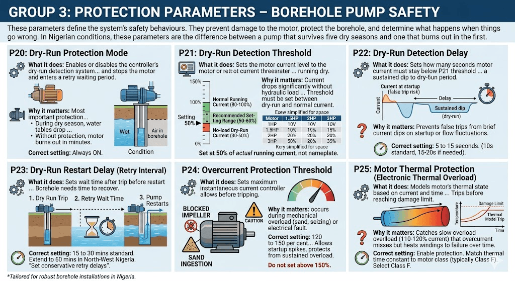
Group 3: Protection Parameters
These parameters define the system’s safety behaviours. They prevent damage to the motor, protect the borehole, and determine what happens when things go wrong. In Nigerian conditions, these parameters are the difference between a pump that survives five dry seasons and one that burns out in the first.
P20: Dry-Run Protection Mode
What it does: Enables or disables the controller’s dry-run detection system. When enabled, the controller monitors motor current. If current drops below the dry-run threshold (P21) for longer than the detection delay (P22), the controller stops the motor and enters a retry waiting period.
Why it matters: This is the most important protection parameter for Nigerian boreholes. During dry season, water tables drop. A pump that was running perfectly in October may find itself pumping air by January if the water table drops below the pump setting depth. Without dry-run protection, the motor runs in air, loses cooling, and burns out in minutes.
Correct setting: Always ON. There is no legitimate reason to disable dry-run protection on any Nigerian borehole installation.
What it does: Sets the motor current level below which the controller considers the pump to be running dry. Expressed as a percentage of rated motor current.
Why it matters: When a pump runs with water, it works against hydraulic resistance and draws close to its rated current. When running dry, there is no hydraulic load and current drops significantly, often to 30 to 50 per cent of rated current.
The threshold must be set between the no-load dry-run current and the normal running current. Set it too high and the controller trips during normal light-load conditions (small tank, partially open valve). Set too low and it fails to detect a genuine dry run.
Motor Rated Current
Typical Dry-Run Current
Recommended P21 Setting
Notes
3.4A (1 HP)
1.0 to 1.5A (30-45%)
Set at 50% of rated (1.7A)
Adjust up if trips during normal low-flow
5.0A (1.5 HP)
1.5 to 2.0A (30-40%)
Set at 50% of rated (2.5A)
Standard starting point
6.8A (2 HP)
2.0 to 3.0A (30-44%)
Set at 50% of rated (3.4A)
Monitor for first two weeks after install
10.0A (3 HP)
3.0 to 4.5A (30-45%)
Set at 50% of rated (5.0A)
Larger motors have more variability
After installation, monitor actual running current at full tank with good solar input. The pump is properly loaded when current is 80 to 100 per cent of rated. Set the dry-run threshold at 50 per cent of actual running current, not 50 per cent of nameplate rated current, for the most accurate protection.
P22: Dry-Run Detection Delay
What it does: Sets how many seconds the motor current must stay below the P21 threshold before the controller confirms a dry-run condition and stops the motor.
Why it matters: When the pump first starts or when flow rates fluctuate briefly, motor current may dip below the threshold momentarily without indicating a true dry-run. A detection delay prevents false trips from brief current dips.
Correct setting: 5 to 15 seconds. A 10-second delay is appropriate for most Nigerian boreholes. If the pump trips on startup before reaching full speed (current is still building during acceleration), increase the delay to 15 to 20 seconds rather than lowering the threshold.
P23: Dry-Run Restart Delay (Retry Interval)
What it does: Sets how long the controller waits after a dry-run trip before attempting to restart the pump. During this wait, the borehole water table has time to recover.
Why it matters: A pump that dry-runs and immediately retries will simply dry-run again. The borehole needs time to recover. If the controller retries too quickly and the borehole has not recovered, the pump runs dry again, trips again, and this cycle repeats until the motor burns out from accumulated heat.
Correct setting: 15 to 30 minutes for most Nigerian boreholes. In boreholes with very low recharge rates (common in North-West Nigeria in dry season), extend to 60 minutes. If the borehole regularly dry-runs even with 60-minute retry intervals, the pump is set too shallow or the borehole yield is insufficient for the demand.
A 30-minute retry delay is not a problem. A burned-out motor in February when the borehole is your only water source is a serious problem. Set conservative retry delays.
P24: Overcurrent Protection Threshold
What it does: Sets the maximum instantaneous current the controller will allow before tripping on overcurrent fault. Typically expressed as a percentage of motor rated current.
Why it matters: Overcurrent conditions occur when the motor is mechanically overloaded (blocked impeller, sand ingestion, seized bearing) or when there is an electrical fault. The overcurrent threshold defines how much above rated current the motor can briefly draw before the controller trips.
Correct setting: 120 to 150 per cent of motor rated current. This allows normal startup current spikes during acceleration without tripping, while protecting against sustained overload. Do not set above 150 per cent.
P25: Motor Thermal Protection (Electronic Thermal Overload)
What it does: Models the motor’s thermal state based on current drawn and time. Even if current stays below the overcurrent threshold, sustained operation at 110 to 120 per cent of rated current accumulates heat in the windings over time. The thermal model trips the controller before the motor reaches its thermal damage limit.
Why it matters: A motor running at 115 per cent rated current will not immediately trip the overcurrent protection. But sustained operation at this level will heat the windings to failure over 30 to 90 minutes. The thermal model catches this slow overload condition.
Correct setting: Enable this protection. Set the thermal time constant to match your motor class. Standard submersible pump motors are typically Class F insulation with a 155-degree Celsius thermal limit. The controller manual will have a thermal class setting that corresponds to this. Select Class F.
Group 4: External Control and Signal Parameters
These parameters define how the controller interacts with external devices: float switches, pressure sensors, remote start signals, and display outputs. In Nigerian installations, these settings determine how well the system manages its storage tank and responds to real-world demand.
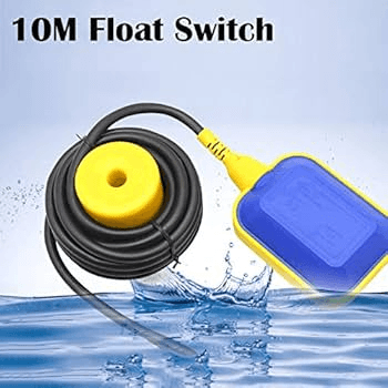
P30: Float Switch Input Mode
What it does: Configures the digital input terminal that receives the signal from a float switch at the storage tank. When the float switch signals tank full, the controller stops the pump. When the float drops, the controller starts the pump again.
Why it matters: Without a properly configured float switch input, the pump runs continuously once started, regardless of whether the tank is full. This wastes pumping time and energy and causes the pump to run against a closed or restricted outlet, increasing motor temperature.
Float Switch Type
Contact State When Tank Full
P30 Setting Required
Normally Open (NO) float switch
Contact CLOSES when tank full
Set input to: Stop pump on contact CLOSE
Normally Closed (NC) float switch
Contact OPENS when tank full
Set input to: Stop pump on contact OPEN
No float switch installed
No signal
Disable float switch input. Pump runs on timer or manual stop only.
Normally Open (NO) float switches are more common and safer. In a wire-break condition (cut wire, loose terminal), the input reads Open, which means the controller sees a non-full tank signal and continues pumping. A Normally Closed switch in a wire-break condition falsely signals tank full and stops the pump. For critical water supply, Normally Open switches are therefore the safer choice.
P31: Low-Level Borehole Switch Input
What it does: Configures a second digital input for a low-water level switch inside the borehole casing. This is a separate physical sensor from the float switch. When the water level in the borehole drops to a critical low level, this switch signals the controller to stop the pump immediately.
Why it matters: The borehole low-level switch provides hardware-level dry-run protection independent of the current-sensing protection in P20 to P22. It is a belt-and-suspenders approach: if the motor current-based dry-run detection fails to detect a problem (for example, because the threshold was set too low), the physical borehole switch provides a second line of defence.
In practice, borehole low-level switches are rarely installed in Nigeria due to cost and complexity. The current-based dry-run detection in P20 to P22 is the primary protection. But for commercial farm installations or community water supply schemes where failure is unacceptable, installing a borehole electrode-type level sensor is strongly recommended.
P32: Remote Start and Stop Input
What it does: Configures the controller’s response to a remote start or stop signal from an external source. This input allows the pump to be controlled by a timer relay, an automated irrigation controller, a GSM remote switch, or a building automation system.
Common configurations in Nigerian installations:
Timer relay: closes at sunrise, opens at sunset. Pump runs during daylight hours and stops at night regardless of tank level.
GSM remote switch: allows the farm owner to start or stop the pump via SMS or phone call from anywhere. Increasingly popular for remote farm installations in Nigeria.
Irrigation controller: solenoid valve controller that starts the pump when irrigation zones open and stops it when all zones are closed.
P33: Analog Output Signal (4-20mA or 0-10V)
What it does: Configures an analog output signal that the controller sends to external monitoring equipment. The signal can represent motor speed, output frequency, motor current, or input power, depending on configuration.
Practical use in Nigeria: This output is connected to a data logger, a SCADA system on large farms, or a simple panel meter displaying pump current or speed. For most residential installations this parameter is left at its default or disabled. For commercial farm installations where pump performance monitoring is critical, configure this output to represent motor current and connect it to a panel-mounted ammeter for continuous monitoring.
Group 5: Display and Communication Parameters
P40: Display Language
Most solar pump controllers sold in Nigeria are imported Chinese units with English and Chinese language options. Ensure the display is set to English before handing the system over to a customer or operator. Parameters set in Chinese cannot be verified or adjusted by most Nigerian technicians.
P41: Password Protection
What it does: Allows the installer to set a PIN code that prevents unauthorised access to the parameter menu.
When to use: Always set a password on any installation where the end user is not a trained technician. In rural Nigeria, it is common for an operator to accidentally change a parameter while exploring the controller menu, disabling protection features without realising it.
Record the password in the installation report. Provide it to the system owner in writing. A forgotten controller password often means a factory reset, which wipes all custom parameters.
P42: Communication Protocol (RS485 / Modbus)
What it does: Configures the RS485 serial communication port used for connecting the controller to a monitoring system, data logger, or building management system.
For most Nigerian residential and small farm installations, this parameter is not used. For commercial installations integrating with a SCADA system or remote monitoring platform, configure RS485 with Modbus RTU protocol at 9600 or 19200 baud rate as required by the monitoring system.
Complete Parameter Reference Table for Borehole Pump Installations
Use this as your quick-reference commissioning sheet. Adjust values based on your specific motor nameplate and borehole depth.
Param
Function
Correct Setting for Nigeria
Common Wrong Setting
Effect of Wrong Setting
P01
Minimum start voltage
70-75% of array Voc
Too low (50% Voc)
Motor starts on insufficient power, stalls, overheats
P02
Max input voltage
Factory default (do not change)
Raised above rated max
Destroys controller transistors on first cold morning
P10
Motor rated power (kW)
Exact nameplate value
Rounded up to next size
Over-current threshold too high, motor unprotected
P11
Motor rated voltage
Exact nameplate value
220V set for a 380V motor
V/Hz ratio wrong, motor runs with wrong flux level
P12
Motor rated frequency
50 Hz
60 Hz
V/Hz curve wrong, motor runs hot at all speeds
P13
Motor rated current
Exact nameplate FLC
Set 20% high to avoid trips
Motor overload allowed, windings overheat over time
P14
Motor rated speed
Exact nameplate RPM
Default 1,500 RPM for 4-pole motor
Speed display wrong, slip compensation slightly off
P15
Acceleration time
8-12 sec for 1-2 HP solar
2-3 sec (industrial default)
Overcurrent trip every morning start, motor stall risk
P16
Deceleration time
15-25 sec for deep boreholes
3-5 sec (industrial default)
Water hammer in long pipe runs, joint failures
P17
Minimum output frequency
20-25 Hz
5-10 Hz (factory default)
Motor runs at cooling-insufficient speed, overheats
P18
Maximum output frequency
50 Hz (55 Hz max)
60 Hz
Motor overspeeds, bearing wear, impeller damage
P20
Dry-run protection
Always ON
OFF (disabled)
Motor burns out when borehole runs dry in dry season
P21
Dry-run threshold
50% of actual running current
30% (too low)
Dry-run not detected, motor burns out
P22
Dry-run detection delay
10-15 seconds
2 seconds (factory default)
False trips during startup and brief current dips
P23
Dry-run retry delay
20-30 minutes
5 minutes (factory default)
Repeated restarts before borehole recovers, heat buildup
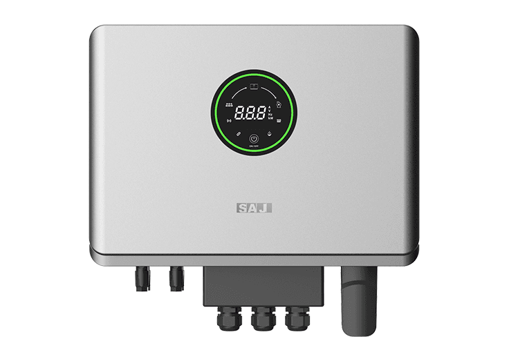
One of the most common solar VFDs for residential installations in Nigeria. Parameters are accessed by holding the SET button for 3 seconds. Navigate with UP/DOWN arrows. Confirm with SET.
Key parameter locations on SAJ: Minimum start voltage is typically F1-01 or F2-01 depending on firmware version. Motor parameters are in the F1 group. Protection parameters are in the F3 group. Do not confuse the pump control parameters (P group) with the motor control parameters (F group) in SAJ controllers.
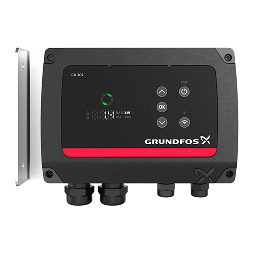
Grundfos CU200 / CU300 Controller
Used with Grundfos SQFlex pumps. Parameter access is via the handheld CU300 display unit or through the Grundfos GO app via Bluetooth. Parameters are named rather than numbered. Key settings include: Minimum flow, Maximum flow, Dry-run timeout, Float switch input type, and Stop pressure.
The Grundfos CU series is significantly more user-friendly than generic Chinese controllers. Parameters are labelled in plain language and the controller guides you through setup with on-screen instructions. Still record all settings before and after commissioning.
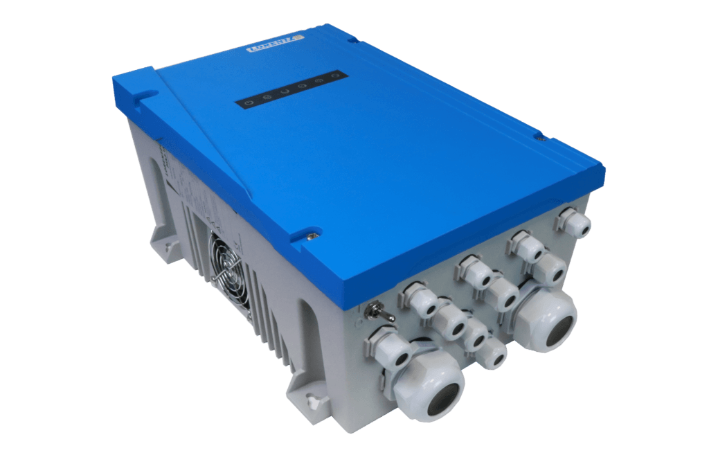
Used with Lorentz PS2 pump systems. Configured via the Lorentz COMPASS software on a laptop or via the Lorentz PUMP EXPERT app on a smartphone. Connection is via Bluetooth dongle or USB.
All commissioning for Lorentz systems is done through the software, not on the controller keypad. The software provides guided setup with automatic pump curve loading for all Lorentz pump models. After commissioning, the settings are uploaded to the controller. Print the COMPASS configuration report and store it with the installation documentation.
Generic Chinese Solar VFD Controllers (SAJ, Solarmax, Veikong, Gozuk, and Others)
The parameter numbering varies between manufacturers and even between firmware versions of the same brand. Always obtain and read the specific manual for your exact model and firmware version before commissioning.
For generic controllers with unlabelled or poorly translated manuals, the function of each parameter can usually be identified by its position in the parameter groups and the range of values it accepts. Cross-reference with the parameter guide in this article to identify equivalent functions.
What to Do When a Parameter Change Causes Unexpected Behaviour
If a parameter change causes the pump to behave unexpectedly (trips immediately on start, runs too slowly, does not stop at tank full), follow this recovery sequence:
Power down the controller immediately. Do not allow the system to continue running in an unknown state.
Retrieve your pre-commissioning parameter photo record.
Restore the changed parameter to its original value.
Power up and test. If the original behaviour returns, you have identified the parameter causing the issue.
Change only one parameter at a time when troubleshooting. Multiple simultaneous changes make it impossible to identify which change caused which effect.
If you cannot restore the original state and the system is completely non-functional, perform a factory reset. Then re-enter all parameters from your commissioning record. This is why taking photos of every parameter before making changes is non-negotiable.
A factory reset erases all custom parameters. Without a commissioning record, you must re-commission the entire controller from scratch. In a remote rural installation with a non-technical operator, a full re-commission may require a technician trip that costs more than the controller itself.
Summary
Solar pump controller parameters are not arbitrary menu items. Each one is an engineering control that directly affects motor lifespan, borehole safety, daily pumping output, and system reliability.
The five parameters that matter most for Nigerian conditions are: minimum start voltage (P01), acceleration time (P15), dry-run protection threshold (P21), dry-run retry delay (P23), and float switch input mode (P30). Get these five right and your system will run reliably through ten dry seasons. Leave them at factory defaults and you are gambling with your motor.
Always record your settings before and after commissioning. Always set a password. Always verify dry-run protection is active before signing off any installation.
Q1: My solar pump controller is showing a fault code I cannot find in the manual. What should I do?
First, photograph the fault code and the current parameter readings on the display. Power down the system. Check the wiring connections at both the solar array input and the motor output terminals. Loose or corroded terminals are the cause of more than 40 per cent of unexplained fault codes on Nigerian installations. If wiring checks out, search for the fault code on the manufacturer’s website or contact their technical support with your controller model number. For generic Chinese controllers without manufacturer support in Nigeria, the fault code meaning can often be found in the Modbus register map in the full technical manual, which is different from the user manual.
Q2: Can I set my solar pump controller parameters without the motor connected?
You can enter motor nameplate data and system parameters without the motor connected. However, you cannot verify any motor protection thresholds, including dry-run detection, without actually running the motor. Never assume protection parameters are set correctly without a live test with the motor running. Power up with the motor connected, run the pump at the surface before lowering it into the borehole, and verify each protection function by testing it.
Q3: My pump starts in the morning but trips after 2 hours. What parameter should I check?
Two-hour runtime before tripping typically indicates a thermal protection trip (P25). The motor is accumulating heat faster than it can dissipate it. Check three things: first, verify the motor thermal class setting matches your actual motor (Class F for standard submersible motors). Second, check the motor’s actual running current against its rated current. If running current exceeds rated current consistently, the pump is working against more head than it is rated for and the system is undersized. Third, check that the minimum output frequency (P17) is not set below 20 Hz. Running at very low frequencies reduces cooling water flow past the motor.
Q4: How do I know if my dry-run protection is set correctly without running the borehole dry?
The best test method is to close the pump discharge valve fully while the pump is running at surface level before installation. With the discharge closed, the pump recirculates water internally at very low flow. Motor current drops to near no-load level, simulating dry-run current. If the controller correctly trips within the P22 delay time, the threshold is correctly set. Open the discharge, restart the system, and confirm normal operation resumes.
Q5: My controller manual is in Chinese and I cannot read the parameter names. How do I find the dry-run protection setting?
Look for a parameter whose range is 0 to 100 per cent and that sits in the protection parameter group (typically the third or fourth group of parameters). The group usually follows the motor parameter group. The dry-run threshold is typically the parameter that, when changed, alters the current level at which the motor stops. If you have access to the RS485 Modbus register map in the technical manual, the dry-run threshold register is usually labelled as Underload Protection Level or No-Load Current Threshold.
Q6: Should I set a different minimum start voltage for harmattan season versus rainy season?
In principle, yes. During harmattan in northern Nigeria, array output is reduced by dust. Setting the minimum start voltage slightly lower (65 per cent of Voc instead of 75 per cent) allows the controller to attempt starts with slightly less available power. However, the acceleration time must be increased correspondingly to avoid overcurrent trips. In practice, most installers set the start voltage conservatively at 70 to 75 per cent and accept slightly later morning starts during harmattan rather than risk overcurrent trips from premature starts. The practical difference in daily pumping volume is small.
Q7: Can I use the same controller settings for a borehole pump and a surface irrigation pump?
The motor parameters (rated power, voltage, current, frequency) will be the same if the motor is the same. The system parameters must be changed: deceleration time should be shorter for a surface pump with a short pipe run. Dry-run detection current will be different because surface pumps draw different no-load current to submersibles. The float switch configuration will depend on your tank setup. Never copy-paste settings from a borehole installation to a surface pump installation without verifying each parameter against the new application.
I am Engr. Ubokobong Ekpenyong, a solar specialist and lithium battery systems engineer with over five years of hands-on experience designing, assembling, and commissioning off-grid solar and energy storage systems. My work focuses on lithium battery pack architecture, BMS configuration, and system reliability in off-grid and high-demand environments.
Contains information related to marketing campaigns of the user. These are shared with Google AdWords / Google Ads when the Google Ads and Google Analytics accounts are linked together.
90 days
__utma
ID used to identify users and sessions
2 years after last activity
__utmt
Used to monitor number of Google Analytics server requests
10 minutes
__utmb
Used to distinguish new sessions and visits. This cookie is set when the GA.js javascript library is loaded and there is no existing __utmb cookie. The cookie is updated every time data is sent to the Google Analytics server.
30 minutes after last activity
__utmc
Used only with old Urchin versions of Google Analytics and not with GA.js. Was used to distinguish between new sessions and visits at the end of a session.
End of session (browser)
__utmz
Contains information about the traffic source or campaign that directed user to the website. The cookie is set when the GA.js javascript is loaded and updated when data is sent to the Google Anaytics server
6 months after last activity
__utmv
Contains custom information set by the web developer via the _setCustomVar method in Google Analytics. This cookie is updated every time new data is sent to the Google Analytics server.
2 years after last activity
__utmx
Used to determine whether a user is included in an A / B or Multivariate test.
18 months
_ga
ID used to identify users
2 years
_gali
Used by Google Analytics to determine which links on a page are being clicked
30 seconds
_ga_
ID used to identify users
2 years
_gid
ID used to identify users for 24 hours after last activity
24 hours
_gat
Used to monitor number of Google Analytics server requests when using Google Tag Manager
1 minute
You can find more information in our Cookie Policy and .


")


