BMS Protection Explained: Overvoltage, Undervoltage, Overcurrent & Short Circuit
BMS protection explained in detail: understand overvoltage, undervoltage, overcurrent, short circuit, and temperature protection. Learn correct LiFePO4 BMS settings, trip thresholds, and what triggers BMS protection in solar battery systems.
When a BMS trips, most people react in one of two ways. Either they panic and assume the battery is broken, or they reset the BMS and carry on without finding out why it tripped in the first place.
Both responses are wrong. And both are expensive.
A BMS protection trip is not a malfunction. It is the BMS doing exactly what it was designed to do: detecting a condition that would damage or destroy the cells and intervening before permanent harm occurs. Understanding what each protection function does, what triggers it, and what it prevents is the difference between a solar system that runs reliably for a decade and one that fails inside two years.
This article provides an engineering-level breakdown of every protection function built into a capable BMS. We cover the electrochemical mechanism each protection is guarding against, the exact thresholds used for different lithium chemistries, how the BMS responds at the circuit level, how to configure each parameter correctly, and what goes wrong when these protections are misconfigured or disabled.
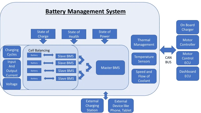
Before going through each protection function individually, it helps to understand the common architecture they all share.
Every BMS protection function has four components:
A monitoring input: a voltage measurement, a current measurement, or a temperature reading from a sensor.
A threshold: a configured limit that defines the boundary between normal operation and a fault condition.
A detection circuit: hardware or firmware that continuously compares the monitored value against the threshold.
A response action: what the BMS does when the threshold is crossed. This is almost always one of two things: switching off a MOSFET to break a circuit, or broadcasting a reduced operating limit to the inverter via CAN or RS485.
The speed of the response varies by protection type. Short circuit protection must respond in under 200 microseconds because the energy involved in a direct short circuit is enough to damage cells in milliseconds. Temperature protection can respond over seconds because thermal events develop slowly. Overvoltage and undervoltage protection respond within tens of milliseconds, fast enough to prevent damage during normal charging and discharging.
The broadcasting of operating limits to the inverter (CVL, CCL, DCL) is one of the most important and underappreciated aspects of BMS protection. This dynamic limit system is explained in full in our article on CVL, CCL, and DCL: dynamic battery limits in real time.
Complete BMS Protection Reference:
Protection Function
Trigger Condition
BMS Response
Response Time
Typical Threshold
Damage Prevented
Overvoltage (OVP)
Cell voltage exceeds upper limit
Hard disconnect of charge path + CVL broadcast to inverter
<100 ms
3.65V (LiFePO4) / 4.20V (NMC/NCA)
Electrolyte oxidation, gas generation, thermal runaway (NMC/NCA)
Undervoltage (UVP)
Cell voltage drops below lower limit
Hard disconnect of discharge path + DCL = 0 broadcast
<100 ms
2.50V (LiFePO4) / 3.00V (NMC/NCA)
Copper dissolution, cathode damage, internal short circuit risk
Cell venting, fire, explosion in worst-case NMC/NCA scenarios
Overtemperature charge (OTP-C)
Cell or MOSFET temp exceeds safe charge limit
CCL reduced proportionally; full cutoff at hard limit
<1 s
45-55 degC typical hard cutoff
Electrolyte decomposition (hot), lithium plating (cold), capacity loss
Overtemperature discharge (OTP-D)
Cell temp exceeds safe discharge limit
DCL reduced; full cutoff at hard limit
<1 s
55-65 degC typical hard cutoff
Accelerated SEI growth, electrolyte degradation, thermal runaway risk
Cell imbalance (BAL)
Cell voltage delta exceeds balance threshold
Balancing circuit activates on high cells
Continuous
Delta >20 mV triggers balancing (typical)
Reduced usable capacity, chronic over/under-charge of individual cells
HOW TO USE THIS TABLE
Use this as a commissioning checklist. Before signing off any lithium battery installation, verify that each protection function is configured, that thresholds match the installed chemistry, and that communication between the BMS and inverter is active. An installation where any row in this table is unconfigured, disabled, or communicating incorrectly is an incomplete installation.
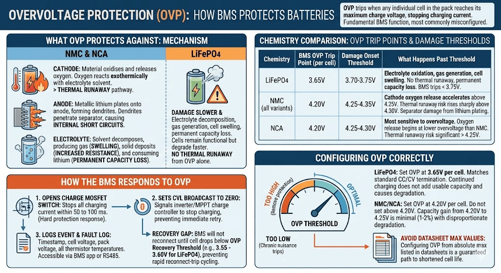
Overvoltage Protection (OVP):
Overvoltage protection is triggered when any individual cell in the pack reaches its maximum charge voltage. It is the most fundamental BMS protection function, and it is the one most commonly misconfigured.
What OVP Protects Against
When a lithium cell is charged beyond its maximum voltage, the normal intercalation chemistry at the cathode completes and cannot accommodate more lithium. Continued charging drives parasitic reactions:
At the cathode: the cathode material begins to oxidise and, in NMC and NCA chemistries, releases oxygen. This oxygen reacts exothermically with the electrolyte solvent. This is the start of the thermal runaway pathway.
At the anode: lithium that cannot intercalate into the fully loaded graphite structure plates onto the anode surface as metallic lithium, forming dendrites. Dendrites grow with subsequent cycles and eventually penetrate the separator, creating internal short circuits.
In the electrolyte: electrolyte solvents decompose faster at elevated cell voltages, producing gas (which causes cell swelling), depositing solid products on electrode surfaces (which increases internal resistance), and consuming lithium from the reversible pool (which permanently reduces capacity).
In LiFePO4, the iron-phosphate cathode does not release oxygen under thermal stress, so thermal runaway does not occur from overvoltage alone. The damage from LiFePO4 overvoltage is slower and more insidious: electrolyte decomposition, gas generation, cell swelling, and permanent capacity loss. The cells remain functional but degrade faster with each overcharge event.
In NMC and NCA, overvoltage is a direct safety risk, not just a longevity concern. A cell pushed significantly past 4.25V is a thermal runaway candidate.
Chemistry
BMS OVP Trip Point (per cell)
Damage Onset Threshold
What Happens Past the Damage Threshold
LiFePO4
3.65V
3.70-3.75V
Electrolyte oxidation, gas generation, cell swelling. No thermal runaway but permanent capacity loss. BMS should trip well before 3.75V.
Most sensitive to overvoltage of the three. Oxygen release begins at lower overvoltage than NMC. Thermal runaway risk is significant above 4.25V.
How the BMS Responds to OVP
When the BMS voltage monitoring circuit detects that any cell has reached the OVP threshold, it takes the following actions in sequence:
It opens the charge MOSFET switch, immediately stopping all charging current from entering the pack. This is the hard protection response and occurs within 50 to 100 milliseconds.
It sets the Charge Voltage Limit (CVL) broadcast to zero or to the current pack voltage, signalling the inverter or MPPT charge controller to stop charging. This prevents the charger from immediately attempting to re-energise the charge path after reset.
It logs the event with a timestamp, the triggering cell voltage, the pack voltage at the time of the event, and the temperatures recorded by all thermistors. This fault log is accessible via the BMS app or RS485 readout.
The BMS will not reconnect the charge path until the triggering cell’s voltage drops below the OVP recovery threshold, typically 3.55 to 3.60V for LiFePO4. This recovery gap prevents rapid reconnect-trip cycling.
Configuring OVP Correctly
The OVP threshold must match the chemistry installed. Setting it too high removes protection. Setting it too low causes chronic nuisance trips during normal charging.
LiFePO4: Set OVP at 3.65V per cell. This matches the standard CC/CV charge termination voltage. Any cell reaching 3.65V during charging is at full charge; continued charging at this voltage does not add usable capacity and only causes degradation.
NMC/NCA: Set OVP at 4.20V per cell. Do not set above 4.20V to try to extract more capacity. The capacity gain between 4.20V and 4.25V per cell is minimal (roughly 1 to 2% of total capacity) and the degradation cost is disproportionate.
The specific dangers of configuring OVP from cell datasheet maximum values rather than system-level analysis are documented in our article: 6 dangers of setting BMS cutoffs from cell datasheets alone. Many cell datasheets list an absolute maximum voltage that is higher than the recommended operating maximum. Using the absolute maximum as the OVP threshold is a guaranteed path to shortened cell life.
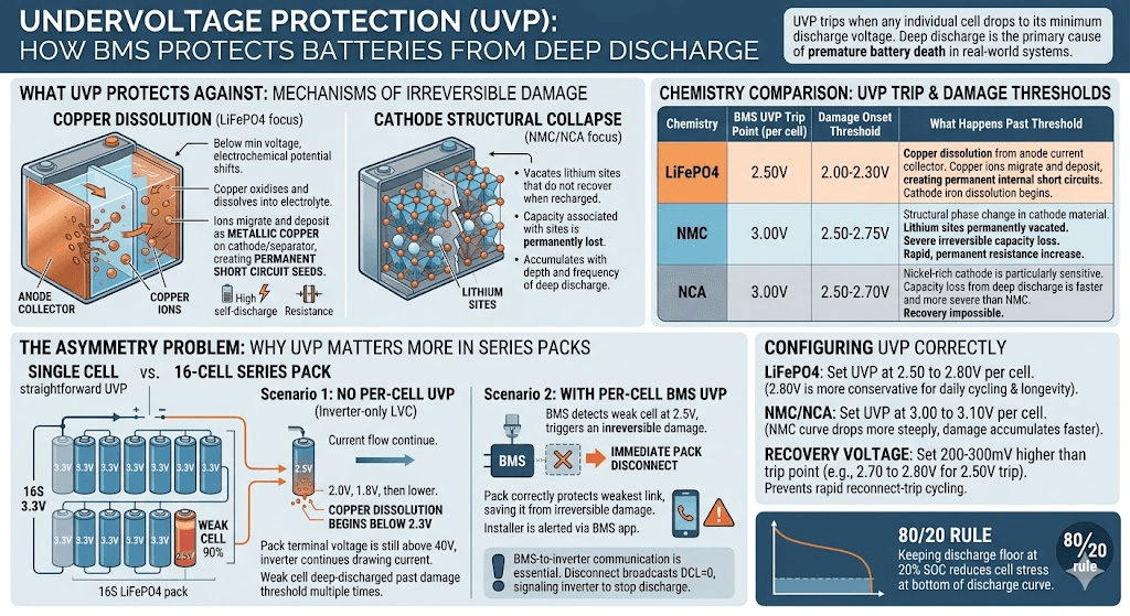
Undervoltage Protection (UVP):
Undervoltage protection is triggered when any individual cell drops to its minimum discharge voltage. Of all the failure modes BMS protection guards against, deep discharge is responsible for the highest proportion of premature battery deaths in real-world solar storage systems.
What UVP Protects Against
Deep discharge damages lithium cells through two primary mechanisms, both of which are irreversible once triggered.
The first mechanism is copper dissolution. The anode current collector beneath the graphite layer is made of copper foil. Below the minimum discharge voltage, the electrochemical potential shifts such that copper begins to oxidise and dissolve into the electrolyte as copper ions. These copper ions migrate across the cell and can deposit as metallic copper on the cathode or separator. Metallic copper deposits inside a cell are permanent short circuit seeds. Even if the cell recovers some capacity after recharging, the copper deposits remain and create elevated self-discharge and internal resistance.
The second mechanism is cathode structural collapse. In NMC and NCA chemistries, deeply discharging the cell vacates lithium sites in the cathode crystal lattice that do not recover when the cell is recharged. The capacity associated with those sites is permanently lost. The more deeply and frequently a cell is discharged past its minimum threshold, the faster this structural damage accumulates.
Chemistry
BMS UVP Trip Point (per cell)
Damage Onset Threshold
What Happens Past the Damage Threshold
LiFePO4
2.50V
2.00-2.30V
Copper dissolution from anode current collector. Copper ions migrate and deposit as metallic copper, creating permanent internal short circuits. Cathode iron dissolution also begins.
NMC
3.00V
2.50-2.75V
Structural phase change in cathode material. Lithium sites permanently vacated. Severe irreversible capacity loss. Internal resistance increase is rapid and permanent.
NCA
3.00V
2.50-2.70V
Nickel-rich cathode is particularly sensitive. Capacity loss from deep discharge is faster and more severe than NMC. Recovery of any kind is impossible once the threshold is crossed.
Why UVP Matters More in Series Packs
In a single-cell application, UVP is straightforward: one cell, one voltage to monitor, one threshold to set. In a series pack of 16 cells, the problem is asymmetric and this asymmetry is what makes UVP genuinely critical in solar storage.
Consider a realistic scenario: a 16S LiFePO4 pack where one cell has drifted to 90% of the capacity of its neighbours due to accumulated imbalance. During discharge, this weaker cell empties faster. When it hits 2.5V, the pack terminal voltage is still above 40V and the inverter is still drawing current, because 15 cells are still at healthy voltages.
Without per-cell UVP, the discharge continues. The weak cell is driven to 2.0V, then 1.8V, then lower with each successive discharge cycle. Copper dissolution begins below 2.3V. By the time the pack terminal voltage has dropped enough to trigger the inverter’s low-voltage cutoff, the weak cell may have been deep-discharged past the damage threshold dozens of times.
With BMS UVP monitoring each cell individually, the weak cell reaching 2.5V triggers an immediate pack disconnect. The other 15 cells still have capacity remaining, but the pack correctly protects the weakest link. The installer is alerted to the weak cell situation via the BMS app and can investigate before the damage becomes irreversible.
This is why BMS communication with the inverter is essential, not optional. When the BMS disconnects due to UVP, it broadcasts DCL = 0 to the inverter, signalling it to stop requesting discharge. An inverter operating without BMS communication cannot receive this signal and may interpret the BMS disconnect as a wiring fault, repeatedly attempting to draw current. See our guide on BMS-to-inverter communication troubleshooting for how to verify and configure this link correctly.
Configuring UVP Correctly
LiFePO4: Set UVP at 2.50 to 2.80V per cell. The higher end of this range (2.80V) is more conservative and extends cell life by preventing discharge into the lowest, most stressful part of the LiFePO4 discharge curve. For systems that cycle daily and prioritise longevity over maximum capacity utilisation, 2.80V is the better choice.
NMC/NCA: Set UVP at 3.00 to 3.10V per cell. The NMC discharge curve drops more steeply at the bottom than LiFePO4, and the damage from excursions below 3.0V accumulates faster.
Recovery voltage: Set the UVP recovery threshold 200 to 300mV above the trip threshold. For LiFePO4 with a 2.50V trip, set recovery at 2.70 to 2.80V. This prevents the pack from reconnecting immediately when a small charge restores the weak cell just barely above the trip threshold.
The 80/20 rule for lithium batteries is directly related to UVP configuration: keeping the discharge floor at 20% SOC rather than 0% reduces cell stress at the bottom of the discharge curve and extends cycle life significantly. Our article on why 100% maximum usable capacity is a lithium battery death sentence explains the electrochemical mechanism behind this operational rule.
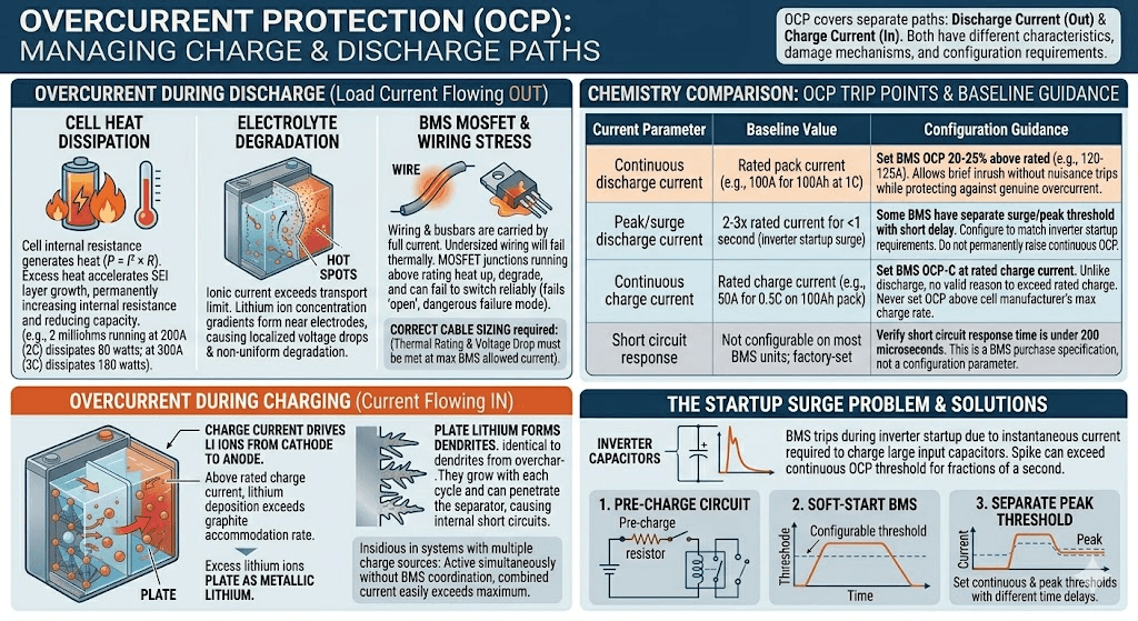
Overcurrent Protection (OCP):
Overcurrent protection covers two separate current paths: discharge current (load current flowing out of the battery) and charge current (current flowing in from solar panels, MPPT controllers, or grid charging). Both directions have different characteristics, different damage mechanisms, and different configuration requirements.
Overcurrent During Discharge: What It Protects Against
Lithium cells have a maximum continuous discharge current rating, typically expressed as a C-rate. A 100Ah cell rated at 1C continuous can deliver 100A. At currents above the rated maximum, three things happen simultaneously.
First, the cell’s internal resistance generates heat proportional to I-squared times R. A cell with 2 milliohms of internal resistance running at 200A (2C) dissipates 80 watts of heat inside the cell. At 300A, that rises to 180 watts. This heat accelerates the growth of the Solid Electrolyte Interphase layer on the anode, permanently increasing internal resistance over time and reducing usable capacity.
Second, the ionic current inside the electrolyte exceeds what the electrolyte can transport cleanly. Lithium ion concentration gradients form near the electrodes, causing localised voltage drops and hot spots that accelerate degradation non-uniformly across the cell.
Third, the wiring, busbars, and MOSFET switches in the BMS carry the full current. Undersized wiring running above its thermal rating will eventually fail. MOSFET junctions running above their rated current heat up and degrade, ultimately failing to switch reliably. A MOSFET that cannot fully open under a fault condition is a particularly dangerous failure mode because it prevents the BMS from protecting the cells.
Correct cable sizing is directly linked to BMS overcurrent settings. Our guide on DC cable sizing for off-grid solar systems covers the two-constraint framework for cable selection: thermal rating and voltage drop. Both constraints must be met at the maximum BMS-allowed discharge current.
Overcurrent During Charging: A Different and Equally Important Problem
Charge overcurrent has a different damage mechanism from discharge overcurrent. During charging, current drives lithium ions from the cathode and deposits them into the graphite anode. Above the rated charge current, the rate of lithium ion deposition exceeds the rate at which the graphite can accommodate them.
The excess lithium ions that cannot enter the graphite structure plate onto its surface as metallic lithium. As covered in the overvoltage section, metallic lithium forms dendrites. Dendrites from charge overcurrent are chemically identical to dendrites from overcharge: they grow with each cycle and eventually penetrate the separator.
Charge overcurrent is a particularly insidious failure mode in systems where multiple charge sources are active simultaneously without proper coordination. If an MPPT charge controller and a generator-powered charger are both charging a battery at the same time, without BMS communication coordinating their current limits, the combined charge current can easily exceed the rated maximum.
Current Parameter
Baseline Value
Configuration Guidance
Continuous discharge current
Rated pack current (e.g., 100A for 100Ah at 1C)
Set BMS OCP threshold 20-25% above rated (e.g., 120-125A). Allows brief inrush without nuisance trips while still protecting against genuine overcurrent.
Peak/surge discharge current
2-3x rated current for <1 second (inverter startup surge)
Some BMS units have a separate surge/peak threshold with a short time delay. Configure this to match inverter startup surge requirements. Do not permanently raise continuous OCP to accommodate surge.
Continuous charge current
Rated charge current (e.g., 50A for 0.5C on 100Ah pack)
Set BMS OCP-C at rated charge current. Unlike discharge, there is no valid reason to exceed rated charge current. Never set charge OCP above the cell manufacturer’s maximum charge rate.
Short circuit response
Not configurable on most BMS units; factory-set
Verify short circuit response time is under 200 microseconds. This is a BMS purchase specification, not a configuration parameter.
The Startup Surge Problem: Why OCP Trips During Inverter Startup
One of the most common OCP-related field problems is the BMS tripping during inverter startup. The issue is well understood once the physics are clear.
Inverters contain large capacitor banks on their DC input stage. When the inverter is first connected to the battery or when it powers up from standby, these capacitors charge from zero to the full pack voltage nearly instantaneously. The current required to charge a capacitor bank is theoretically infinite for an instant, in practice limited only by the resistance of the connecting cables.
This startup current spike can reach several hundred amps for a fraction of a second, easily exceeding the BMS continuous OCP threshold. The BMS trips. The installer thinks the BMS is faulty. The BMS is working exactly as designed.
The correct solutions are:
Pre-charge circuit: A resistor and relay circuit that charges the inverter’s capacitor bank through a current-limiting resistor before connecting the full battery. This limits the inrush to a manageable level.
Soft-start BMS: Some advanced BMS units have a configurable startup mode that temporarily raises the OCP threshold for a defined period (typically 100 to 500 milliseconds) to accommodate inverter startup, then returns to the normal threshold.
Separate peak current threshold: Many smart BMS units allow a separate peak current threshold with a short time delay. Set the peak threshold to cover the startup surge; set the continuous threshold to protect against sustained overloads.
COMMON MISTAKE
Never permanently raise the continuous OCP threshold to accommodate inverter startup surge. A 100A BMS running at a 150A continuous OCP threshold to avoid startup trips is now providing inadequate protection during sustained overloads. The startup surge is a design problem to solve at the hardware level, not by weakening the protection thresholds.
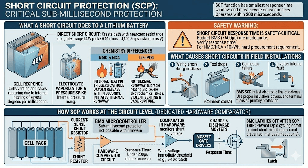
Short Circuit Protection (SCP):
Short circuit protection is the BMS protection function with the smallest response time window and the most severe consequences if it fails to respond adequately.
What a Short Circuit Does to a Lithium Battery
A direct short circuit across the battery terminals creates a path with near-zero resistance between the positive and negative terminals. Ohm’s law governs the result: voltage divided by resistance equals current. With a fully charged 48V pack and a resistance of, say, 0.01 ohms in the short circuit path (low-resistance copper shorting bar), the instantaneous current is 4,800 amps.
At that current, the cells attempt to deliver energy at a rate far beyond their design limits. Internal temperature rises at a rate of several degrees per millisecond. The electrolyte begins to vaporise. Internal pressure spikes rapidly. In NMC and NCA cells, this internal heating is enough to trigger cathode oxygen release within seconds, initiating thermal runaway.
In LiFePO4, the same current spike heats the cells rapidly and causes severe electrochemical stress, but thermal runaway does not typically result. The more immediate danger is mechanical: cells can vent violently, cases can rupture, and the connecting wiring and terminals can sustain fire-level temperatures from the I-squared R heating.
How SCP Works at the Circuit Level
Short circuit protection uses a dedicated hardware comparator circuit, separate from the microcontroller that handles other BMS functions. This matters because microcontrollers have software overhead, interrupt latency, and clock cycle limitations that make sub-millisecond response impossible for firmware-based protections.
The SCP comparator monitors the voltage across the current-sense shunt resistor continuously in hardware. When the voltage across the shunt exceeds the threshold corresponding to the short circuit current (typically 5 to 10 times the rated continuous current), the comparator immediately fires the MOSFET gate drivers to open both the charge and discharge MOSFETs simultaneously. This entire process occurs in under 200 microseconds on a properly designed BMS.
After a short circuit trip, the BMS remains latched off. It will not auto-reset until the short circuit condition is cleared and the BMS is manually reset or a configured timeout period passes. This prevents the BMS from rapidly cycling on and off while a short circuit is still present, which would subject the MOSFETs to repeated high-current stress.
SAFETY WARNING
Short circuit response time is a safety-critical BMS specification. Budget BMS units with response times above 500 microseconds provide inadequate short circuit protection, particularly for NMC and NCA packs where the thermal runaway window is short. Always verify short circuit response time when specifying a BMS for a system carrying significant stored energy. For NMC or NCA systems above 10kWh, this specification should be a hard procurement requirement.
What Causes Short Circuits in Field Installations
Short circuits in solar battery installations are less dramatic than the term implies. Most are caused by:
Wiring errors during installation: a positive cable touching a grounded metal enclosure, or two conductors with damaged insulation touching each other.
Tool drops: a spanner or screwdriver dropped across battery terminals during maintenance. This is one of the most common causes of short circuit events in field installations.
Connector failure: a corroded or loose terminal that arcs intermittently, which presents as a high-frequency current spike rather than a sustained short.
Inverter internal fault: a failed inverter component creating a low-resistance path from the battery bus to ground.
Good system design minimises short circuit risk through proper insulation, strain relief, terminal covers, and fuse protection at the battery terminal in addition to BMS SCP. The BMS SCP is the last electronic line of defence; it should not be the only protection mechanism against short circuit events.
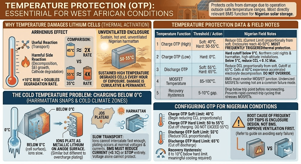
Temperature Protection (OTP):
Of all BMS protection functions, temperature protection is the one most directly relevant to solar storage in Nigeria and across West Africa. The thermal conditions that routinely exist in Nigerian battery installations are precisely the conditions that temperature protection is designed to intercept.
Why Temperature Damages Lithium Cells
Lithium cell electrochemistry is thermally activated. The rates of both the useful reactions (lithium ion transport) and the harmful side reactions (electrolyte decomposition, SEI layer growth, cathode degradation) all increase with temperature. The Arrhenius relationship governs this: for most electrochemical degradation reactions in lithium cells, a 10 degC rise in temperature roughly doubles the reaction rate.
A battery operating continuously at 45 degC is experiencing electrode degradation at approximately twice the rate of the same battery at 35 degC. At 55 degC, it is experiencing degradation at roughly four times the rate of operation at 35 degC. Under Nigerian harmattan conditions, unventilated battery enclosures can sustain 50 to 55 degC for weeks.
The damage from high-temperature operation is cumulative and permanent. Unlike an overvoltage event that can be stopped and cause no further harm, high-temperature operation degrades cells with every hour of exposure, even if temperatures never reach the hard protection threshold.
Temperature Protection
Typical Threshold
Configuration and Field Notes
Charge OTP (high)
45-55 degC (cell surface)
Reduce CCL proportionally from 45 degC; hard cutoff at 55 degC. In Nigerian ambient conditions, battery enclosure temperatures routinely reach 40-50 degC, making this the most frequently triggered thermal protection.
Charge OTP (low)
0 degC (cell surface)
Hard cutoff below 0 degC. Applies primarily to harmattan cold nights in northern Nigeria and high-altitude installations. Below 5 degC, reduce CCL to 0.1C maximum.
Discharge OTP
55-65 degC (cell surface)
Reduce DCL proportionally from 55 degC; hard cutoff at 65 degC. Cells at 60 degC under load are experiencing electrolyte decomposition at an accelerated rate. Do not override this protection.
MOSFET temperature
85-100 degC (MOSFET junction)
BMS should monitor MOSFET temperature separately from cell temperature. Undersized MOSFETs running hot are a common failure mode. A BMS that does not monitor MOSFET temperature directly is a design limitation.
Recovery hysteresis
5-10 degC below trip threshold
After an overtemperature trip, the BMS should require temperature to drop at least 5-10 degC below the trip threshold before reconnecting. This prevents rapid cycling (connect-trip-connect-trip) that stresses MOSFETs.
The Cold Temperature Problem: Charging Below 0 degC
Low-temperature charging is less commonly discussed in the Nigerian context but is relevant for installations in the Jos Plateau, high-altitude northern states, and harmattan cold snaps that push overnight temperatures below 10 degC.
Below 0 degC, lithium ion transport through the electrolyte and into the graphite anode slows dramatically. The ions that cannot intercalate fast enough plate onto the anode surface as metallic lithium. Unlike the plating from overcharge, cold-temperature lithium plating occurs even at normal charge voltages and normal charge currents. The BMS cannot prevent it through voltage monitoring alone; only temperature monitoring triggers the necessary response.
At temperatures below 0 degC, the BMS must either stop charging entirely or reduce the charge current to a level (typically 0.05C to 0.1C) where the intercalation rate can keep pace. This is not a configuration most installers consider, but it is a real failure mode for installations in cold-climate zones.
Configuring Temperature Protection for Nigerian Conditions
For most Nigerian installations, the high-temperature charge protection settings are the critical configuration parameters. Given typical battery enclosure temperatures, the following configuration is appropriate:
Charge OTP soft limit: 40 degC. At this point, begin reducing CCL proportionally to reduce internal heating from charge current.
Charge OTP hard limit: 50 to 55 degC. Cut off charging entirely. Do not accept any installation where this protection is disabled or set higher than 55 degC.
Discharge OTP hard limit: 65 degC. Cut off discharge.
Recovery hysteresis: 8 to 10 degC below the hard limit. After a thermal trip, require the enclosure to cool meaningfully before reconnecting.
If OTP trips are frequent during Nigerian dry-season operation, the root cause is the battery enclosure design, not the BMS. Improve ventilation first. Our guide on why most solar battery systems fail before year 2 covers the specific installation choices that lead to chronic thermal stress in Nigerian conditions.
How Protection Functions Interact: Reading BMS Events Correctly
In real systems, BMS protection events rarely occur in isolation. Understanding how protections interact is the difference between correct diagnosis and chasing the wrong root cause.
Scenario
What Is Happening
Correct Response
OVP trip during bulk charge
BMS opened charge MOSFET because one cell reached OVP threshold
Do not reset and resume. Check individual cell voltages via BMS app. If one cell is significantly above the others, the pack needs balancing time before resuming charging. Check inverter charge voltage setting against BMS OVP threshold.
UVP trip under load
BMS opened discharge MOSFET because one cell hit UVP threshold
This is the BMS working correctly. Check individual cell voltages. If one cell is at 2.5V while others are at 3.1V, that cell is weak and needs investigation. The pack needs recharging before any further discharge attempt.
OCP trip on startup
BMS opened discharge MOSFET due to inverter startup current surge
Check whether the inverter’s startup surge exceeds the BMS continuous OCP threshold. If so, configure BMS peak current threshold or add a pre-charge circuit. Do not raise continuous OCP threshold to accommodate startup surge permanently.
OTP-C trip during midday charging
BMS reduced CCL or cut charge during peak solar hours
Battery enclosure is too hot. Improve ventilation or add forced cooling. This is a system design issue, not a BMS fault. Repeated OTP trips during charging accelerate cell aging through charge deprivation at peak generation periods.
Multiple protections triggering together
BMS shows OVP + OTP-C simultaneously
High temperature charging causes faster voltage rise per cell, triggering OVP at lower SOC than normal. Root cause is thermal. Fix the enclosure temperature problem and the OVP trips will likely resolve too.
Repeated unexplained BMS trips are one of the most common reasons customers report their battery is faulty when it is not. Before concluding that a battery pack is defective, pull the BMS fault history and read the individual cell voltages at the time of each trip. The data tells the complete story. Our article on inverter battery percentage wrong and our guide on battery dies faster than expected cover the most common misdiagnosis patterns that result from not reading BMS protection events correctly.
What Most Installers Get Wrong About BMS Protection
MISTAKE 1
Setting BMS protection thresholds from the cell datasheet absolute maximum ratings rather than the recommended operating parameters. Cell datasheets list an absolute maximum voltage that is higher than the safe operating maximum. Using the absolute maximum as the OVP threshold means the BMS will not trip until the cell is already in a damaging condition. Always set OVP at the charge termination voltage, not the absolute maximum.
MISTAKE 2
Disabling or raising protection thresholds to stop nuisance trips without diagnosing the root cause. Nuisance trips are the BMS responding to a real condition. Raising thresholds or disabling protections to stop trips removes protection without fixing the problem. The underlying cause (cell imbalance, wrong inverter settings, overheating enclosure) continues to develop and eventually causes irreversible damage.
MISTAKE 3
Not connecting the BMS communication cable and then wondering why the inverter does not respect BMS protection signals. A BMS disconnected from the inverter’s communication bus can only protect through hard circuit disconnects. It cannot broadcast reduced CVL, CCL, or DCL to moderate the inverter’s behaviour before a hard trip becomes necessary. The result is more frequent hard trips, more stress on MOSFET switches, and less graceful system behaviour during edge conditions.
MISTAKE 4
Using a BMS with a short circuit response time above 500 microseconds in an NMC or NCA system. This is a hardware specification issue, not a configuration issue. Budget BMS units commonly have slow SCP response due to firmware-based detection rather than hardware comparator circuits. For any chemistry other than LiFePO4, verify SCP response time before purchase. For LiFePO4, it matters less due to the chemistry’s thermal stability, but fast SCP response is still preferable.
For a complete catalogue of installation and configuration mistakes that lead to premature battery failure, our article on off-grid solar mistakes covers the system-level errors that compound BMS configuration problems.
Recommended BMS Protection Settings for LiFePO4 in Nigerian Solar Systems
The following configuration represents a tested, field-validated starting point for 16S LiFePO4 packs in Nigerian off-grid and hybrid solar installations. Adjust based on specific cell manufacturer recommendations and system load profiles.
Parameter
Recommended Setting
Notes
Cell OVP trip
3.65V
Matches standard LiFePO4 charge termination voltage. Do not set higher.
Cell OVP recovery
3.55V
10mV hysteresis prevents rapid re-trip after reset.
Cell UVP trip
2.80V
Conservative setting for daily cycling. Extends cycle life vs 2.50V setting.
Cell UVP recovery
3.00V
Requires a meaningful recharge before reconnecting discharge path.
Discharge OCP
125% of rated
e.g., 125A for a 100A-rated BMS. Covers brief load spikes without nuisance trips.
Charge OCP
Rated max
No reason to exceed cell manufacturer’s maximum charge rate. Set exactly at rated value.
Short circuit threshold
Factory set
Verify response time under 200us. This is a purchase spec, not a configurable parameter on most BMS units.
Charge OTP (soft)
40 degC
Begin CCL reduction. Critical for Nigerian dry-season operation.
Charge OTP (hard)
50 degC
Full charge cutoff. Improve enclosure ventilation if this trips regularly.
Discharge OTP (soft)
55 degC
Begin DCL reduction.
Discharge OTP (hard)
65 degC
Full discharge cutoff.
OTP recovery hysteresis
8-10 degC
Require meaningful cooling before reconnection.
Cell balance start threshold
20mV delta
Begin balancing when highest and lowest cells differ by 20mV or more.
Communication protocol
Match inverter
CAN for Victron; RS485 Modbus for Deye/Growatt. Must be configured, not just physically connected.
For inverter-specific communication configuration paired with these BMS settings, our guide on inverter-battery communication protocols covers the exact parameter settings for Victron, Deye, and Growatt inverters.
Frequently Asked Questions
What does BMS overvoltage protection do?
BMS overvoltage protection monitors the voltage of each individual cell in real time. When any cell reaches the maximum charge voltage threshold (3.65V for LiFePO4, 4.20V for NMC), the BMS opens the charge MOSFET switch, stopping all charging current from entering the pack. It simultaneously broadcasts a reduced Charge Voltage Limit to the inverter to prevent the condition from recurring immediately after reset.
What is BMS undervoltage protection?
Undervoltage protection monitors each cell’s voltage during discharge. When any cell drops to its minimum threshold (typically 2.50 to 2.80V for LiFePO4), the BMS opens the discharge MOSFET, disconnecting all loads. This protects the weak cell from being driven below the damage threshold where copper dissolution and cathode structural damage become irreversible.
What is the difference between overcurrent and short circuit protection?
Overcurrent protection responds to current that exceeds the rated maximum over a period of milliseconds: a sustained overload. Short circuit protection responds to a near-instantaneous current spike many times above the rated maximum, consistent with a direct terminal short. Short circuit protection uses a dedicated fast comparator circuit and responds in under 200 microseconds. Overcurrent protection typically responds within 1 to 5 milliseconds.
What triggers BMS overcurrent protection?
BMS overcurrent protection triggers when discharge current exceeds the configured threshold, typically 120 to 150% of the rated continuous current. Common triggers include: inverter startup surge exceeding the threshold, a faulty load drawing excessive current, undersized BMS for the installed inverter, or a partial wiring short creating high-resistance fault current.
What voltage should my BMS overvoltage protection be set to?
For LiFePO4, set OVP at 3.65V per cell. For NMC and NCA, set OVP at 4.20V per cell. These are the standard charge termination voltages for each chemistry. Setting OVP higher than these values does not give the cells more charge; it exposes them to electrolyte oxidation and thermal stress. Setting OVP lower than these values causes premature charge termination and reduces usable capacity.
Why does my BMS keep tripping on overvoltage?
Repeated OVP trips during charging usually mean one of three things: (1) the inverter charge voltage is set higher than the BMS OVP threshold, (2) one or more cells are significantly out of balance and reaching the OVP threshold before the rest of the pack is full, or (3) the balancing current is too low to correct the imbalance between charge cycles. Check individual cell voltages via the BMS app to identify which cell is triggering the protection.
What happens when the BMS trips for short circuit?
The BMS opens both charge and discharge MOSFETs simultaneously within microseconds, creating an open circuit between the cells and the external terminals. The inverter sees zero battery voltage and enters a fault state. The BMS remains disconnected until the short circuit condition is cleared and the BMS is reset, either manually or after a timeout period depending on the BMS model.
Does BMS temperature protection stop charging in hot weather?
Yes. When cell temperatures exceed the configured high-temperature charge limit (typically 45 to 55 degC), the BMS reduces the Charge Current Limit broadcast to the inverter and eventually cuts off charging entirely. In Nigerian conditions, this is one of the most frequently triggered BMS protections during the dry season. The solution is improved battery enclosure ventilation, not disabling the protection.
What is the BMS recovery voltage?
Recovery voltage is the cell voltage at which the BMS resets after an undervoltage trip and allows the battery to be charged again. It is set slightly above the UVP trip threshold, typically 2.80 to 3.00V for LiFePO4. The gap between UVP trip and recovery voltage prevents rapid cycling where the BMS disconnects and reconnects repeatedly as a load drains the pack to the trip threshold.
How do I know which BMS protection triggered?
Connect to the BMS using its Bluetooth app or RS485/CAN readout tool. All smart BMS units maintain a fault history log showing which protection triggered, at what timestamp, and what the cell voltages and temperatures were at the time of the event. This data is the most reliable way to diagnose repeated BMS trips without guessing.
I am Engr. Ubokobong Ekpenyong, a solar specialist and lithium battery systems engineer with over five years of hands-on experience designing, assembling, and commissioning off-grid solar and energy storage systems. My work focuses on lithium battery pack architecture, BMS configuration, and system reliability in off-grid and high-demand environments.
Contains information related to marketing campaigns of the user. These are shared with Google AdWords / Google Ads when the Google Ads and Google Analytics accounts are linked together.
90 days
__utma
ID used to identify users and sessions
2 years after last activity
__utmt
Used to monitor number of Google Analytics server requests
10 minutes
__utmb
Used to distinguish new sessions and visits. This cookie is set when the GA.js javascript library is loaded and there is no existing __utmb cookie. The cookie is updated every time data is sent to the Google Analytics server.
30 minutes after last activity
__utmc
Used only with old Urchin versions of Google Analytics and not with GA.js. Was used to distinguish between new sessions and visits at the end of a session.
End of session (browser)
__utmz
Contains information about the traffic source or campaign that directed user to the website. The cookie is set when the GA.js javascript is loaded and updated when data is sent to the Google Anaytics server
6 months after last activity
__utmv
Contains custom information set by the web developer via the _setCustomVar method in Google Analytics. This cookie is updated every time new data is sent to the Google Analytics server.
2 years after last activity
__utmx
Used to determine whether a user is included in an A / B or Multivariate test.
18 months
_ga
ID used to identify users
2 years
_gali
Used by Google Analytics to determine which links on a page are being clicked
30 seconds
_ga_
ID used to identify users
2 years
_gid
ID used to identify users for 24 hours after last activity
24 hours
_gat
Used to monitor number of Google Analytics server requests when using Google Tag Manager
1 minute
You can find more information in our Cookie Policy and .