Active vs Passive Balancing: Which BMS Balancing Method Is Better?
Active vs passive balancing explained at the circuit level. Learn how each method works, why passive balancing fails in high-cycling solar systems, and when active balancing is worth the cost.
Of all the questions that come up when specifying a BMS for a solar storage system, balancing is the one most frequently answered with the wrong information.
The common narrative goes something like this: passive balancing is fine for most systems, and active balancing is an optional upgrade for people with money to spare. This narrative is wrong. In a solar storage system that cycles daily, passive balancing is not just suboptimal. In many configurations, it is functionally inadequate.
Understanding why requires going past the marketing summaries and into the actual circuit-level behaviour of each balancing method, the mathematics of imbalance accumulation, and the specific conditions of daily solar cycling that make balancing performance a determinant of long-term pack health rather than a secondary consideration.
This article covers all of it. By the end, you will have a precise, defensible engineering basis for selecting the right balancing method for any lithium battery installation.
This article is part of the Eneronix BMS content cluster. For the foundational context on why balancing exists and what it protects against, see our articles on what is a BMS and why lithium batteries fail without a BMS.
Why Cell Balancing Exists
Every series-connected lithium battery pack has a fundamental structural problem: cells in series share the same current but do not share the same state of charge.
When you connect 16 LiFePO4 cells in series to build a 48V nominal pack, those cells are electrically constrained to carry the same current at all times. Charge flows in and out of every cell at the same amperage. But the cells themselves are not identical. They never are.
Even cells from the same production batch, tested to tight tolerances, have small variations in three parameters that determine how they behave in a series string over time.
The Three Sources of Cell Divergence
1. Capacity Variation
A cell rated at 100Ah from one manufacturer may have an actual capacity anywhere from 97Ah to 103Ah depending on where it falls within the production tolerance. In a 16S pack, if one cell has a true capacity of 96Ah and another has 104Ah, the 96Ah cell fills up faster on every charge cycle and empties faster on every discharge cycle. After 500 cycles, this small original difference has compounded into a measurable operational difference.
The practical effect: the lowest-capacity cell reaches full charge voltage first on every charge cycle. The charger, responding to pack terminal voltage, terminates charging when the pack appears full. But the other cells may only be at 95% SOC. On discharge, the same low-capacity cell hits the undervoltage limit first, triggering the BMS to disconnect the entire pack even though other cells still have 10 to 15% capacity remaining.
The usable capacity of the pack is permanently bounded by the lowest-capacity cell, not the average.
2. Self-Discharge Rate Variation
All lithium cells self-discharge when sitting at rest, losing a small fraction of their charge per day. For LiFePO4, this is typically 1 to 3% per month. But individual cells vary. A cell with a slightly higher self-discharge rate enters every charge cycle at a fractionally lower SOC than its neighbours.
Over time, this means the high-self-discharge cell is never at the same SOC as the others at any point in the cycle. It is always slightly behind on charge and slightly ahead on discharge. The balancing circuit must continuously compensate for this ongoing divergence, not just the initial factory mismatch.
3. Internal Resistance Variation and Growth
Internal resistance determines how much the cell voltage drops under load. A cell with higher internal resistance shows a larger voltage drop when current flows through it. In a series string where all cells carry the same current, the higher-resistance cell shows a lower terminal voltage under the same load compared to its lower-resistance neighbours.
Internal resistance also grows with age, temperature exposure, and cycling. Cells that experience more thermal stress or are more frequently pushed to voltage extremes age faster. Their internal resistance grows faster than cells in more benign positions. Over 500 to 1,000 cycles, the internal resistance spread across a 16-cell pack can become significant, creating voltage distribution patterns that make the pack behave as though it is more imbalanced than its actual SOC differential would suggest.
The interaction between cell aging, internal resistance growth, and cycle life is covered in depth in our article on how charge and discharge cycles affect lithium battery lifespan. Understanding this progression explains why balancing requirements increase, not decrease, as a pack ages.
Passive Balancing
The Circuit Mechanism
Passive balancing is simple to understand and inexpensive to implement, which explains its prevalence in budget BMS units.
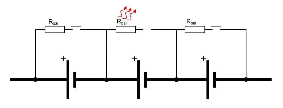
Each cell in the pack has a dedicated bypass circuit consisting of a power resistor and a MOSFET switch connected in parallel with the cell. The BMS monitors all cell voltages continuously. When any cell’s voltage exceeds a defined threshold relative to the other cells, the BMS closes the MOSFET for that cell, connecting the bypass resistor in parallel.
Current from the charging source now has two paths through that cell: the normal path through the cell itself, and the bypass path through the resistor. The resistor diverts a portion of the charging current away from the cell, slowing its rate of charge. The cell’s voltage rise rate decreases. If the resistor conducts enough current, the cell’s voltage stabilises or even begins to fall as the resistor dissipates energy faster than the charging source can add it.
When the cell voltage drops back to within the balance threshold of its neighbours, the BMS opens the MOSFET and the bypass resistor is disconnected.
The energy that flowed through the resistor did not go to any useful purpose. It became heat. Every joule of energy that passive balancing removes from a high cell is wasted.
The Balancing Current Problem
The bypass resistor value determines the balancing current: the current diverted from the cell and dissipated as heat. This is the critical performance parameter for passive balancing.
A typical resistor value in a consumer passive BMS is 10 to 33 ohms per cell. At 3.65V cell voltage, a 33-ohm resistor draws approximately 110mA. A 10-ohm resistor draws approximately 365mA.
These currents sound plausible until you look at the task they need to perform. Consider a 200Ah LiFePO4 pack that has developed a 5% capacity imbalance between its strongest and weakest cell. The energy difference between these two cells at the same terminal voltage is approximately 10 Ah. To correct a 10 Ah imbalance using a 100mA balancing current requires 100 hours of continuous balancing.
A solar battery system in daily use has approximately 6 to 8 hours of charging available per day, of which perhaps 1 to 2 hours are spent in the constant-voltage phase at the top of charge where balancing is most effective. At 100mA, the BMS corrects perhaps 0.1 to 0.2 Ah of imbalance per day. The pack develops new imbalance through cycling faster than passive balancing removes it.
This is not a marginal deficiency. It is a systematic failure to perform the function it is advertised to perform. The pack drifts progressively further out of balance with each passing month, silently, without any fault codes or alarms.
Our dedicated analysis of this failure mechanism in high-cycling solar applications: why passive balancing BMS fails in high-discharge solar battery systems, documents the specific degradation pattern in quantitative terms. It is the most important supplementary reading to this article.
The Heat Problem in Nigerian Conditions
Passive balancing has a second critical problem that is specific to hot-climate installations: it adds a heat load to the BMS PCB and the battery enclosure at precisely the time when thermal management is most important.
Balancing happens at the top of charge, during the CV phase, when the solar array is still producing maximum power on a sunny afternoon. In a Nigerian installation, this is also when ambient temperatures are at their highest, often between 35 and 42 degC outside and 40 to 50 degC inside an unventilated battery enclosure.
Scenario
Continuous Power Dissipation
Energy Wasted per Charge Cycle
Thermal Impact in Nigerian Conditions
100 mA at 3.65V (1 cell balancing)
0.365 W
2.19 Wh over 6-hour charge
Negligible for one cell
100 mA at 3.65V (4 cells balancing simultaneously)
1.46 W
8.76 Wh over 6-hour charge
Moderate heating of BMS PCB. Raises enclosure temperature 3-5 degC.
200 mA at 3.65V (4 cells balancing simultaneously)
2.92 W
17.52 Wh over 6-hour charge
Significant. In a 40 degC enclosure this brings the BMS to 48-52 degC, approaching thermal stress territory.
200 mA at 3.65V (8 cells balancing simultaneously)
5.84 W
35.04 Wh over 6-hour charge
Severe in hot climates. BMS PCB can exceed 60 degC. Balance resistors may burn. This scenario occurs when a pack is first installed with poorly matched cells.
In a poorly ventilated installation with 4 to 8 cells balancing simultaneously during a hot afternoon charge cycle, the BMS PCB temperature can reach 55 to 65 degC. This is above the safe operating temperature for most BMS microcontrollers and close to the thermal limit for standard electrolytic capacitors used in BMS designs. The consequence is accelerated BMS component aging and eventually BMS hardware failure, typically appearing as erratic cell voltage readings, stuck balance resistors, or complete BMS failure.
FIELD OBSERVATION
In Nigerian solar installations where BMS hardware failure is diagnosed, a significant proportion involve passive BMS units installed in poorly ventilated enclosures. The root cause is not the cells, not the inverter, and not the wiring. It is the combination of passive balance resistor heating added to an already elevated enclosure temperature. The BMS thermally degrades over 12 to 24 months and eventually fails to measure cell voltages accurately, allowing imbalance to compound unchecked.
When Passive Balancing Is Acceptable
Passive balancing is not universally unsuitable. There are specific conditions where it performs adequately:
Small packs under 100Ah with low cycling frequency (weekly or less). A 100Ah pack cycling once per week accumulates imbalance much more slowly. Even 100mA of passive balancing current can keep pace.
Well-matched cells with tight factory tolerances, particularly cells that have been top-balanced before assembly. Starting with near-zero imbalance means the BMS only needs to correct the slow drift from self-discharge and aging, not a large initial mismatch.
Cost-constrained builds where the budget does not support a smart active BMS, and the user accepts the tradeoff of faster long-term capacity loss in exchange for lower upfront cost.
For every scenario outside these three conditions, active balancing is the correct engineering choice.
Active Balancing
Active balancing does not waste energy. It moves energy. The difference sounds simple, but it changes the performance mathematics entirely.
The Core Principle
In an active balancer, the circuit monitors cell voltages and identifies the highest-voltage cell and the lowest-voltage cell in the pack. It then transfers charge from the high cell to the low cell using a switching power conversion circuit that preserves most of the transferred energy.
The mechanism for energy transfer differs by topology, but the result is the same: the high cell’s voltage decreases, the low cell’s voltage increases, and the energy that moved between them is available as useful charge rather than heat. Conversion efficiency for well-designed active balancers runs from 80 to 95%, meaning 80 to 95 cents of every dollar of energy moved from the high cell arrives at the low cell.
Topology
How It Works
Advantages
Limitations
Inductor-based (cell-to-cell)
A switched inductor transfers charge directly between adjacent cells. Current flows into the inductor from the higher-voltage cell, then releases into the lower-voltage cell.
High efficiency (85-92%). Fast response. Direct cell-to-cell transfer means energy does not pass through the entire string. Most common in JK BMS active balancer series.
Balancing is only between adjacent cells. Large imbalances spanning many cells require multiple transfer steps. Inductor can saturate if balance current is set too high.
Capacitor-based (flying capacitor)
A capacitor is alternately connected across a high-voltage cell to charge, then switched across a low-voltage cell to discharge into it.
Simple control. No magnetic components. Good for moderate balancing currents.
Lower efficiency than inductor-based (typically 75-85%). Balancing current limited by capacitor size and switching frequency. Less common in modern BMS designs.
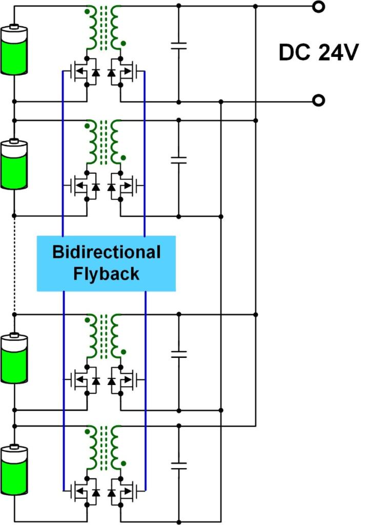
Transformer-based (multi-winding)
A multi-winding transformer with one winding per cell allows energy to be transferred from any cell to any other cell in a single conversion step.
Highest flexibility. Can transfer between any two cells regardless of position in the string. Used in premium BMS designs for large packs.
Most complex and expensive. Transformer must be wound for the specific cell count. Rarely seen in standard consumer BMS products; more common in custom industrial designs.
DC-DC converter (pack-to-cell)
Energy is taken from the entire pack (high voltage bus) and delivered to individual low-voltage cells via a DC-DC converter.
Simple control logic. Can charge any single cell from pack energy regardless of position.
Lower efficiency than cell-to-cell methods because energy traverses the full voltage difference. Can cause imbalance if converter fails on one channel.
The JK BMS series uses an inductor-based cell-to-cell active balancing topology. Understanding this specific implementation is practical because it is one of the most widely deployed active balancers in the Nigerian and West African solar storage market.
The JK BMS PCB contains one or more dedicated balancing inductors, typically rated at 4.7 to 10 microhenries. Associated gate driver ICs and MOSFETs form a switching circuit for each adjacent cell pair. The balancing control algorithm monitors all cell voltages and identifies the delta between the highest and lowest cell.
When the delta exceeds the configured start threshold (typically 5 to 30mV, configurable via the app), the algorithm selects the highest-voltage cell and begins a switched-inductor transfer toward the lowest-voltage cell. Current flows from the high cell into the inductor on one switching half-cycle (storing energy in the inductor’s magnetic field), then releases from the inductor into the low cell on the other half-cycle.
The cycle repeats at switching frequencies of 50 to 200 kHz, allowing effective balancing currents of 1 to 2A despite the small physical size of the inductor. At 2A, the same 10 Ah imbalance that takes passive balancing 100 hours to correct takes active balancing approximately 5 hours, well within a single overnight charge cycle.
The JK BMS allows the balancing current to be configured in the app, typically in a range from 0.1A to the maximum rated current. This matters because maximum balancing current during the absorption charge phase generates some heat, and in a hot enclosure, reducing balancing current to 1A instead of 2A is a reasonable thermal management tradeoff that still outperforms any passive alternative.
A Direct Comparison
Abstract principles are convincing. Specific numbers are decisive. The following worked example uses a 200Ah 16S LiFePO4 pack with a realistic 5% capacity imbalance scenario.
Parameter
Passive Balancing (100 mA)
Active Balancing (2A)
Pack capacity
200 Ah
200 Ah
Cell count
16S
16S
Target imbalance to correct
10 Ah (5% of pack capacity between weakest and strongest cell)
10 Ah (same scenario)
Balancing current
100 mA
2,000 mA (2A)
Time to correct imbalance
10 Ah / 0.1A = 100 hours (4+ days of continuous balancing)
10 Ah / 2A = 5 hours (corrected within a single overnight charge)
Practical outcome
Imbalance grows faster than passive balancing can correct it in daily cycling systems. The pack drifts progressively out of balance.
Imbalance is corrected each charge cycle before it can compound. Pack maintains tight cell matching over years of use.
Energy wasted in correction
~0.365V x 0.1A x 100h = 3.65 Wh wasted as heat
~0.365V x 2A x 5h x 0.1 loss factor = 0.365 Wh lost (95% efficiency)
ENGINEERING REALITY
The 100-hour correction time for passive balancing is not a worst case. It is a realistic calculation for a common scenario. In practice, balancing only occurs during the CV charging phase (not the entire charge cycle), which in a typical solar system with 6-8 hours of solar input runs for 1-2 hours per day. Effective passive balancing time is therefore 1-2 hours daily, meaning 50 to 100 days to correct a 10 Ah imbalance. During those 50 to 100 days, new imbalance is being added by cycling. The pack never catches up.
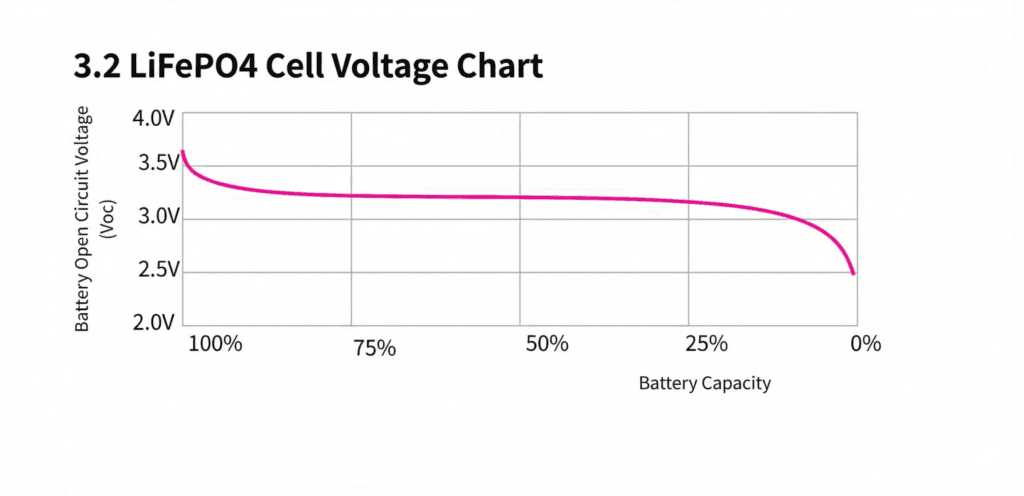
The LiFePO4 Flat Voltage Curve:
LiFePO4 is the best lithium chemistry for solar storage in nearly every respect. But it has one characteristic that makes balancing more technically demanding than NMC or NCA: its discharge voltage curve is almost completely flat.
Between 90% and 20% SOC, a LiFePO4 cell’s open-circuit voltage changes by only 50 to 100mV, staying in the narrow range of 3.20 to 3.30V. This is excellent for load compatibility (stable voltage to the inverter throughout discharge) but terrible for voltage-based SOC estimation and voltage-triggered balancing.
Why Flat Curve Breaks Passive Balancing
Passive balancing is triggered by voltage differences between cells. When one cell’s voltage is above the others by a defined threshold, the bypass resistor activates.
For an NMC pack, cell voltage varies significantly with SOC across the full discharge range. Imbalance between cells translates clearly into voltage differences that trigger passive balancing reliably throughout the charge and discharge cycle.
For a LiFePO4 pack, cell voltage is nearly identical between cells at any SOC between 20% and 90%. Two cells with 10% SOC difference between them, one at 60% SOC and one at 50% SOC, may show a voltage difference of only 5 to 20mV at rest. This is barely above the measurement noise floor for most BMS cell-monitoring ICs and is well below the threshold that triggers passive balancing on most consumer BMS units.
The imbalance is real. The cells genuinely have different states of charge. But passive balancing, relying on voltage as its only signal, cannot reliably detect it in the middle of the LiFePO4 discharge range.
Balancing is only truly effective in LiFePO4 packs at the very top of the charge curve, above 3.40V per cell, where the voltage curve steepens and small SOC differences translate into measurable voltage differences. This narrow window means passive balancing has only a brief window of effectiveness per charge cycle, compounding its already inadequate current limitation.
How Active Balancing Handles the Flat Curve
Active balancers with higher balancing current are less dependent on the voltage differential for trigger logic. A well-designed active balancer can be set to activate at any cell voltage delta above 5mV and still transfer enough charge at 2A to make meaningful corrections, even when the voltage difference between cells is small.
The higher current means the balancer does not need to wait for voltage differences to become large before acting. It can correct small, early-stage imbalances before they compound into large ones, maintaining tight cell matching throughout the life of the pack rather than only reacting to imbalance after it has become significant.
The specific algorithms used by smart BMS systems to detect and correct imbalance in LiFePO4 packs, including SOC-based rather than purely voltage-based balancing triggers, are analysed in our article: how smart BMS balancing algorithms protect lithium battery packs.
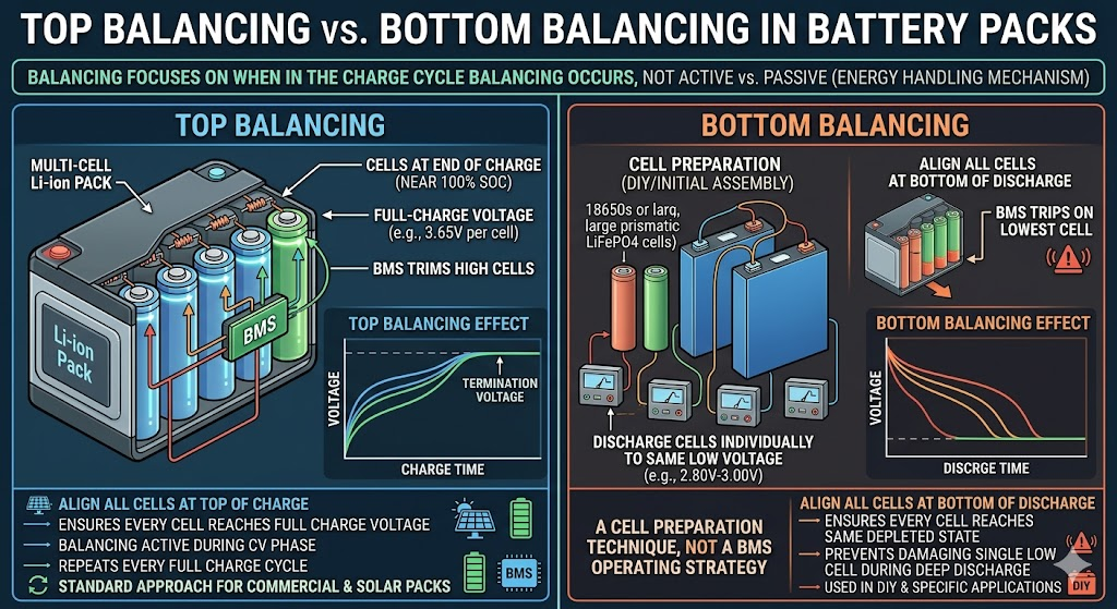
Top Balancing vs Bottom Balancing
Active vs passive describes the energy handling mechanism. Top vs bottom balancing describes when in the charge/discharge cycle balancing occurs. These are different questions with different answers.
Top Balancing
Top balancing aligns all cells at the top of charge, ensuring every cell reaches the same full-charge voltage before the BMS terminates charging. The balancing circuit is active during the CV phase at the end of charging, trimming high cells down (passive) or redistributing charge from high to low cells (active) until all cells are at the same voltage at 100% SOC.
Top balancing is the standard approach for virtually all commercial lithium battery packs and most BMS designs. For solar storage applications where the daily cycle involves charging to full capacity each day, top balancing is appropriate and effective.
Bottom Balancing
Bottom balancing aligns all cells at the bottom of discharge, ensuring every cell reaches the same depleted state before the pack trips the undervoltage protection. This approach is used in specific applications where the pack is routinely discharged to near-empty.
Bottom balancing is relevant for DIY builders assembling packs from scratch. Before first use, some builders discharge all cells individually to the same low voltage (typically 2.80 to 3.00V for LiFePO4), then assemble and connect them to the BMS. This ensures all cells start at the same base state. The BMS then top-balances during subsequent charge cycles.
For operational solar storage systems already in service, top balancing is the standard and bottom balancing is not an operational mode. It is a cell preparation technique, not a BMS operating strategy.
Balancing During Discharge: Rest Balancing
Some advanced BMS platforms, including certain JK BMS configurations, can perform balancing during discharge or at rest (when the pack is neither charging nor discharging). This rest balancing uses the same active balancing circuitry but draws energy from the pack itself to power the transfer.
Rest balancing is useful for packs that do not reach full charge regularly, for example in cloudy weather sequences or systems with conservative SOC upper limits. If the pack never fully charges to the CV phase, top balancing never activates. Rest balancing allows correction to continue regardless.
The tradeoff is a small self-discharge from the pack due to the balancing circuit’s own current consumption. For most systems this is negligible, but it is a design consideration for systems where standby self-discharge must be minimised.
The Selection Guide: Active or Passive for Your System
The following table provides clear decision guidance based on installation characteristics. Use it as a specification tool, not a preference guide.
Installation Scenario
Recommended Balancing Type
Engineering Rationale
Small pack (under 100Ah), low cycling (weekly or less), cost-constrained build
Passive
Acceptable. Low cycling frequency means imbalance accumulates slowly. Passive balancing can keep pace.
100-200Ah pack, daily cycling, off-grid solar home system
Active
Required for long-term pack health. Passive balancing current is insufficient to correct daily imbalance accumulation in this capacity range.
200Ah+ pack, daily deep cycling, commercial or off-grid installation
Active (high current, 2A+)
Non-negotiable. At this capacity and cycling frequency, passive balancing is functionally useless. Use JK BMS active balancer or equivalent with 2A+ balancing current.
DIY pack from cells with known good factory matching (within 1% capacity)
Passive acceptable initially
Well-matched cells diverge slowly. Passive balancing may be adequate for the first 1-2 years. Plan to upgrade to active balancing as cells age and diverge.
DIY pack from cells with unknown or wide factory variation
Active required
Wide cell variation means significant imbalance from day one. Only active balancing with sufficient current can correct large initial imbalances quickly enough to prevent premature capacity loss.
Manufacturer-specified (usually passive with occasional active correction)
This decision is made by the manufacturer. The BMS inside commercial batteries is matched to the cell quality and cycling expectations of that product.
High-temperature Nigerian installation (enclosure temps 40-50 degC regularly)
Active strongly preferred
Passive balancing adds resistive heat load to an already hot enclosure. Active balancing generates minimal heat and avoids compounding the thermal stress.
For sizing guidance that integrates balancing requirements with overall battery bank design, our battery bank sizing guide for off-grid systems covers the complete specification process including BMS selection criteria.
What to Look for When Specifying an Active Balancer
Not all active balancers are equal. When evaluating a BMS for its active balancing capability, the following parameters determine real-world performance:
Balancing Current Rating
This is the single most important active balancer specification. Higher is better, subject to thermal management constraints. For a 100Ah pack cycling daily, a minimum of 1A active balancing is required. For 200Ah and above, 2A is the practical target. Units claiming 5A active balancing exist but require careful attention to heat management.
Balancing Topology
Inductor-based cell-to-cell (as used in JK BMS) is the most energy-efficient and responsive topology available in standard consumer BMS products. Prefer this over capacitor-based or pack-to-cell topologies for solar storage applications.
Balancing Activation Threshold
Should be configurable, not fixed. For LiFePO4, a start threshold of 5 to 15mV is ideal: sensitive enough to catch early-stage imbalance but not so sensitive that it activates from measurement noise. A fixed threshold BMS set at 50 to 100mV will miss a significant amount of LiFePO4 imbalance entirely.
Balancing Mode
Confirm whether the BMS balances only during charging, only during CV phase, during discharge, or at rest. For most solar storage applications, charging-only top balancing is sufficient. Rest balancing is a useful feature for systems with irregular charging patterns.
Independent Balancing Control
On higher-tier BMS units, balancing can be enabled or disabled independently of the protection functions. This allows balancing to be tuned without affecting the protection configuration, which is useful during initial commissioning when cells may need extended balancing before the system is placed in normal service.
What Most Installers Get Wrong About Balancing
MISTAKE 1
Assuming the BMS is balancing effectively because no fault codes appear. Passive balancing does not generate fault codes when it is failing to keep pace with imbalance accumulation. The cells drift apart silently. The only way to confirm balancing is working is to connect to the BMS app and read individual cell voltages over time. A widening voltage delta between the highest and lowest cell during a charge cycle is a direct indicator that balancing is not keeping pace.
MISTAKE 2
Specifying a passive BMS for a 200Ah or larger pack in a daily-cycling solar installation because it is cheaper. The upfront saving of passive over active balancing (typically 15 to 30 USD difference for a 48V BMS) is recovered within the first year through avoided capacity loss. After 3 years of daily cycling, an actively balanced 200Ah pack retains meaningfully more usable capacity than a passively balanced pack of identical cells. The lifetime cost of passive balancing in large solar installations is higher, not lower.
MISTAKE 3
Setting the active balancing start threshold too high. A JK BMS configured with a 100mV balance start threshold will not activate balancing until the delta between cells is already significant. For LiFePO4, the correct setting is 5 to 20mV. This keeps the cells tightly matched throughout their life rather than allowing large imbalances to develop before correction begins.
MISTAKE 4
Installing an active balancer BMS in a sealed, unventilated enclosure without accounting for balancing heat. Active balancing generates less heat than passive but is not zero heat. At 2A balancing current and 5% conversion loss, the balancer dissipates approximately 0.365 watts. In a sealed enclosure this is negligible. But if the BMS is also running high temperatures from ambient heat, the combined thermal load should still be considered in enclosure design.
For the full catalogue of installation decisions that lead to premature battery failure in Nigerian solar systems, our article on why most solar battery systems fail before year 2 is the definitive reference. Balancing inadequacy is one of the top three root causes documented across field installations.
Active vs Passive Balancing: Complete Technical Reference
The following table provides a consolidated engineering comparison of both methods across all relevant parameters.
Parameter
Passive Balancing
Active Balancing
Balancing mechanism
Burns excess energy from high cells as heat through resistors
Transfers energy from high cells to low cells via inductors or capacitors
Energy efficiency
Low. All balanced energy is lost as heat (0% energy recovery)
High. 80-95% of transferred energy reaches the destination cell
Typical balancing current
30-200 mA (most consumer BMS units)
500 mA to 5A (depending on BMS tier)
Balancing speed
Slow. Hours to days for significant imbalance correction
Fast. Minutes to hours for the same imbalance correction
Heat generated
Significant. Can raise BMS PCB and enclosure temperature
Minimal. Small conversion losses only
Circuit complexity
Simple. Resistors and MOSFETs only
Complex. Inductors, capacitors, control ICs, and gate drivers
BMS unit cost
Low (passive balancing adds negligible cost)
Higher (active balance circuitry adds 20-60% to BMS cost)
Suitable pack capacity
Up to ~100Ah with normal cycling
100Ah and above; essential for 200Ah+ packs with daily cycling
Suitable cycle frequency
Low to moderate (weekly or less)
Daily deep cycling, high discharge rate applications
LiFePO4 flat curve suitability
Poor. Flat curve makes voltage-triggered balancing inaccurate
Good. Higher balancing current corrects imbalance despite flat curve
Long-term pack health
Imbalance accumulates over time in high-cycling systems
Maintains tight cell matching over thousands of cycles
BMS PCB heating
Yes. Balance resistors heat the PCB continuously during charging
Minimal. Small switching losses only
Failure mode
Balance resistor failure, MOSFET stuck closed on one cell
Inductor saturation, gate driver failure, control IC fault
Best application
Low-cost installations, low-cycling, small packs, cost-constrained builds
Solar storage, daily cycling, large packs, longevity-critical installations
The Practical Recommendation for Nigerian Solar Storage
For any lithium battery installation in Nigeria cycling daily in an off-grid or hybrid solar system, the recommendation is unambiguous: specify a BMS with active balancing.
The specific combination that has proven most reliable in the Nigerian market for DIY and custom battery packs in the 48V, 100 to 300Ah range is the JK BMS active balancer series (JK-BMS-B2A8S20P or equivalent for 16S packs) configured with:
Active balance start threshold: 10 mV
Active balance current: 1.5 to 2A (reduce to 1A in installations with confirmed high enclosure temperatures above 45 degC)
Balance mode: charge-only top balancing for standard daily-cycling systems
OVP/UVP thresholds set per the LiFePO4 configuration table from Article 4 of this cluster
CAN or RS485 communication connected and configured to match the installed inverter
For sealed commercial battery units (Pylontech, BYD, Dyness, Huawei), the balancing approach is determined by the manufacturer. These units are matched at the factory and their internal BMS is optimised for the specific cells installed. The selection question for these products is not passive vs active balancing but rather which product tier and capacity matches the system requirements.
What is the difference between active and passive balancing?
Passive balancing dissipates excess energy from higher-voltage cells as heat through resistors, bringing high cells down to match low cells. Active balancing transfers energy from higher-voltage cells to lower-voltage cells using inductive or capacitive circuits, redistributing charge within the pack without wasting it as heat. Passive balancing is simpler and cheaper but slower and less efficient. Active balancing is faster, more energy-efficient, and more effective in high-cycling systems.
Is active balancing better than passive balancing?
For solar storage systems that cycle daily, active balancing is significantly better. The higher balancing current (typically 1 to 5A vs 30 to 200mA for passive) means it can correct daily imbalance accumulation within a single charge cycle. Passive balancing may be adequate for small packs that cycle infrequently, but for any system with 100Ah or more and daily cycling, active balancing is the correct specification.
Why does passive balancing fail in solar storage systems?
Passive balancing fails in solar storage because the balancing current (typically 30 to 200mA) is far too low to correct the imbalance that accumulates through daily deep cycling of large-capacity packs. A 200Ah pack developing a 10Ah imbalance between its strongest and weakest cell would require over 100 hours of continuous passive balancing to correct. In daily cycling applications, new imbalance is added each cycle faster than passive balancing can remove it.
How much balancing current do I need for a 200Ah LiFePO4 pack?
For a 200Ah pack cycling daily, a minimum of 1A active balancing current is required to maintain pack balance over time. A 2A active balancer is the practical target for this pack size. At 2A, a 10Ah imbalance can be corrected within approximately 5 hours, well within the overnight charging window. Passive balancing at 100mA would require 100 hours to correct the same imbalance.
Does active balancing extend battery life?
Yes, meaningfully so. Active balancing maintains tighter cell voltage matching over thousands of cycles compared to passive balancing. Tighter cell matching means no individual cell is chronically overcharged or undercharged, which are the two most direct causes of accelerated cell aging. Field data from high-cycling solar storage applications consistently shows better capacity retention in actively balanced packs versus passively balanced packs of the same cell type over 3 to 5 year horizons.
When does a BMS balance cells?
Most BMS designs only activate balancing during charging, specifically during the constant voltage (CV) phase near the top of charge when cells are close to full. This is called top balancing. Some advanced BMS designs also balance during discharge (bottom balancing) or continuously. For LiFePO4, which has a flat discharge curve, top balancing is the most effective approach because voltage differences between cells are largest and most detectable at the top of the charge curve.
What is the JK BMS active balancer?
The JK BMS is a Chinese-manufactured smart BMS that includes an integrated inductor-based active balancer with a configurable balancing current of up to 2A. It has become one of the most widely used BMS units in the Nigerian and West African solar storage market due to its combination of active balancing, full CAN/RS485 communication, Bluetooth app monitoring, and configurable protection thresholds at a price point significantly below premium alternatives. It is available in 4S to 32S configurations covering 12V to 96V packs.
Can I add active balancing to a BMS that only has passive balancing?
Some active balancer modules can be added externally to packs that have a passive BMS. These modules connect to the cell tap wires and operate independently of the BMS. However, this approach has limitations: the external balancer and the passive BMS are not coordinated, which can cause conflicting behavior, and external balancers add wiring complexity and failure points. The better solution for any new installation is to specify a BMS with integrated active balancing from the start.
What causes cell imbalance in a lithium battery pack?
Cell imbalance originates from three sources that compound over time. First, factory cell variation: cells from the same production batch have small differences in capacity (1 to 5%) and self-discharge rate that cause them to drift apart from the first cycle. Second, differential aging: cells age at slightly different rates depending on their position in the pack, thermal exposure, and the current distribution through the pack. Third, accumulated cycling: each charge and discharge cycle adds a small increment of imbalance that compounds over hundreds or thousands of cycles without correction.
How do I check if my battery pack is out of balance?
Connect to the BMS using its Bluetooth app or RS485 readout tool. The BMS displays individual cell voltages in real time. On a well-balanced pack, all cells should be within 20 to 30mV of each other during charging and discharging. A delta of over 100mV between the highest and lowest cell during normal operation indicates significant imbalance that requires correction. A delta of over 300mV indicates a severely imbalanced or damaged cell that needs urgent investigation.
I am Engr. Ubokobong Ekpenyong, a solar specialist and lithium battery systems engineer with over five years of hands-on experience designing, assembling, and commissioning off-grid solar and energy storage systems. My work focuses on lithium battery pack architecture, BMS configuration, and system reliability in off-grid and high-demand environments.
Contains information related to marketing campaigns of the user. These are shared with Google AdWords / Google Ads when the Google Ads and Google Analytics accounts are linked together.
90 days
__utma
ID used to identify users and sessions
2 years after last activity
__utmt
Used to monitor number of Google Analytics server requests
10 minutes
__utmb
Used to distinguish new sessions and visits. This cookie is set when the GA.js javascript library is loaded and there is no existing __utmb cookie. The cookie is updated every time data is sent to the Google Analytics server.
30 minutes after last activity
__utmc
Used only with old Urchin versions of Google Analytics and not with GA.js. Was used to distinguish between new sessions and visits at the end of a session.
End of session (browser)
__utmz
Contains information about the traffic source or campaign that directed user to the website. The cookie is set when the GA.js javascript is loaded and updated when data is sent to the Google Anaytics server
6 months after last activity
__utmv
Contains custom information set by the web developer via the _setCustomVar method in Google Analytics. This cookie is updated every time new data is sent to the Google Analytics server.
2 years after last activity
__utmx
Used to determine whether a user is included in an A / B or Multivariate test.
18 months
_ga
ID used to identify users
2 years
_gali
Used by Google Analytics to determine which links on a page are being clicked
30 seconds
_ga_
ID used to identify users
2 years
_gid
ID used to identify users for 24 hours after last activity
24 hours
_gat
Used to monitor number of Google Analytics server requests when using Google Tag Manager
1 minute
You can find more information in our Cookie Policy and .


")


")


