Most hybrid solar systems in Nigeria are installed and handed over on the same day. The installer connects the components, turns the system on, confirms that solar is producing and the battery is charging, and leaves.
That is not commissioning. That is installation followed by a power-on test.
According to IEA PVPS data, 18% of PV system faults originate from incomplete or skipped commissioning procedures. In a Nigerian hybrid system, that percentage is higher because the Nigerian context adds specific failure modes that a generic power-on test cannot detect: BMS communication not verified, battery type set to lead-acid on a LiFePO4 system, anti-islanding thresholds set too tight for Nigerian grid conditions, earth resistance not measured, and monitoring not configured.
A system that passes a power-on test can still be:
Slowly destroying its LiFePO4 battery through float charging
Managing the battery on voltage estimates rather than BMS data
Tripping offline during every NEPA brownout due to default voltage thresholds
Operating without earthing continuity in island mode
Producing no data because the monitoring WiFi dongle was never registered
Commissioning closes these gaps before the system is handed over. It is the systematic process of verifying that every component works correctly, every parameter is configured correctly, and every safety function operates as designed.
This checklist covers 10 stages. Each stage has a specific purpose and specific pass or fail criteria. An installation is not complete until all 10 stages are signed off.
Stage 1: Documentation and Design Verification
Before any physical inspection, verify that what was installed matches what was designed. The system should be checked thoroughly before the commissioning starts. Installation matches the design documentation. Conductors, OCPD, and disconnect are sized appropriately. SolarTech
Check these documents against the physical installation:
System single-line diagram: does the wiring topology match the design?
Component specification sheets: are the installed inverter, battery, panels, and protection devices the correct models?
Cable sizing schedule: are the installed cable cross-sections correct for the design currents?
Battery datasheet: do the charge voltage limits, discharge cut-off, and BMS communication protocol on the datasheet match what has been configured in the inverter?
Earth system design: has an earthing electrode been installed, and is it the correct specification?
Labelling verification:
Good labelling lets inspectors map records to hardware in seconds. It also reduces return visits. Combiner boxes: unique ID, string range, maximum fuse rating, and short-circuit current rating. DC isolators: voltage rating, current rating, and lockout method. Inverters: equipment ID, firmware, fault codes legend, and clear AC and DC ratings. Prasun Barua
Every DC isolator, AC circuit breaker, RCBO, and distribution board in the system must be labelled. Every string cable must be labelled at both ends. Every battery terminal must be labelled with polarity. A system without correct labelling fails Stage 1.
Pass criteria: Installed components match design specification. All protection devices and circuits are labelled. Design documents are on site.
A systematic visual inspection identifies potential issues before energised testing begins. The comprehensive checklist should include: module condition (cracks, chips, delamination, or manufacturing defects), wiring integrity (proper connections, strain relief, and insulation condition), grounding system (continuous bonding, proper torque, and corrosion protection). eneronix
Work through the system from the array down to the distribution board.
Solar array inspection:
All panels are firmly seated in their mounting rails with no movement
Panel frames are undamaged, no cracks in glass, no delamination visible
MC4 connectors are fully mated and locked. Pull-test each connector. If it separates without the release tool, it is not properly locked
String cables are routed away from sharp edges, secured every 300mm, and not in contact with the roof surface where abrasion could occur
Array frame and mounting rails are bonded with earth continuity conductor
Plant room inspection:
Inverter is securely mounted with ventilation clearances maintained (minimum 200mm each side, 300mm above and below for most hybrid inverters)
Battery is secured in its rack or enclosure, not resting on the floor unsupported
All DC cables have correct conduit protection from the point of entry into the plant room to the terminals
ANL fuse is installed within 300mm of the battery positive terminal
BMS communication cable is connected at both the battery BMS port and the inverter communication port
All cable terminations are crimped (not twisted and taped), torqued to the manufacturer’s specification, and tinned where humidity is a risk
No exposed live terminals anywhere in the plant room with protection devices open
Distribution board inspection:
Solar DB is a separate unit from the NEPA DB
Individual RCBOs are installed for each output circuit
All circuit breakers and RCBOs are correctly labelled
DB cover is in place and no open knockouts
Pass criteria: No visible defects on any component. All connections are correctly terminated. All clearances are maintained.
Stage 3: Pre-Energisation Electrical Tests
Before the inverter sees a single volt, performing thorough electrical checks is essential. Skipping this step can lead to equipment damage, safety hazards, or failed PV system startup procedure. A detailed solar inverter commissioning checklist ensures that insulation, polarity, and voltage parameters are verified before energising the system, protecting both technicians and the investment. SolarSME
These tests are performed with all isolation devices OPEN and all fuses REMOVED. The system is completely de-energised.
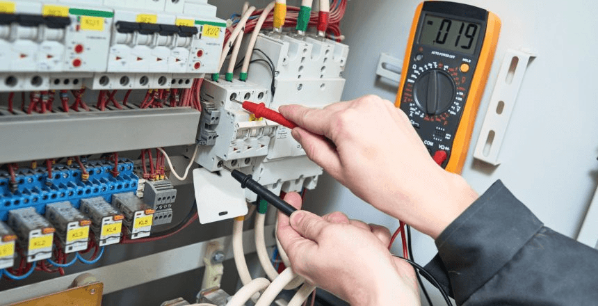
Test 1: DC string polarity verification
Using a multimeter, measure the voltage between the positive and negative string terminals at the inverter MPPT input (with array isolator open, string fuses removed, and array receiving sunlight). Verify:
Voltage is positive (positive terminal reads positive voltage relative to negative terminal)
Voltage magnitude corresponds to the expected string Voc for current irradiance and temperature
A reversed polarity string reading (negative voltage) means the string positive and negative conductors have been swapped. Connecting a reversed string to the MPPT destroys the MPPT immediately.
Test 2: Insulation resistance test
An insulation resistance test is your first line of defense against unexpected ground faults. Start by isolating all PV strings from the inverter. Using a megohmmeter, measure the resistance between each positive and negative conductor to ground. Ideally, resistance should exceed 1 MΩ per string, indicating the insulation is intact and there are no leakage paths. SolarSME
Use a 500V DC megohmmeter for this test. Resistance below 1 MΩ between any string conductor and earth indicates damaged insulation. The fault must be located and repaired before energisation.
Test 3: Battery polarity verification
With the battery isolator OPEN and ANL fuse REMOVED, measure voltage between the battery positive and negative terminals at the inverter DC input. Verify positive polarity and correct voltage (approximately 52V to 54V for a 48V LiFePO4 battery at rest).
Test 4: Earth resistance measurement
Connect an earth resistance tester between the earthing electrode and the inverter earth terminal. Measure earth resistance. The target is below 10 ohms. Above 10 ohms, the earthing electrode is inadequate. Improve before energisation by driving a deeper rod or adding a parallel rod.
Test 5: AC output continuity verification
With all RCBOs open and the inverter switched off, verify continuity from the inverter AC output terminal to the solar DB busbar. Then verify continuity from each DB output to the correct circuit. Verify no AC continuity between the solar DB busbar and the NEPA DB busbar.
Pass criteria: Positive string polarity. Insulation resistance above 1 MΩ per string. Positive battery polarity. Earth resistance below 10 ohms. No inadvertent connection between solar DB and NEPA DB.
Follow the energisation sequence exactly. Deviating from this sequence is the most common cause of arc flash incidents and component damage during commissioning.
Energisation sequence:
Close battery isolator. Insert ANL fuse. Verify battery voltage appears on inverter display (approximately 52V to 54V for 48V LiFePO4 at rest). If the display shows 0V or an error, stop and investigate before proceeding.
Close array isolator. Insert string fuses. Verify MPPT input voltage appears on inverter display. Verify the voltage matches the expected string Voc for current irradiance.
Power on the inverter. Verify the inverter enters its startup sequence without immediately showing a fault code. Common startup fault codes at this stage: HVSD (high voltage shutdown, string voltage above MPPT Vmax), LVSD (low voltage shutdown, string voltage below MPPT Vmin), battery fault (polarity or voltage mismatch).
Verify the inverter AC output shows 230V AC on the display. Do not close any AC RCBOs yet.
Close the main RCBO at the inverter AC output. Verify no fault trip.
Close individual output circuit RCBOs one at a time, monitoring the inverter load display after each one. Verify loads appear on the inverter display and the inverter does not trip.
Close grid input MCB. Verify the inverter detects the grid, synchronises to the grid waveform, and transitions to grid-connected operating mode. Verify the display shows grid voltage and frequency.
Pass criteria: No fault codes during startup. AC output 230V confirmed. Grid synchronisation confirmed. All load circuits energised without trip.
Stage 5: Battery Configuration Verification
This is the most critical configuration stage and the one most frequently skipped in Nigerian installations. A system that passes Stages 1 to 4 can still be incorrectly configured and silently destroying its battery.
Navigate to the battery settings in the inverter menu and verify each parameter:
Parameter
Correct Setting (48V LiFePO4)
Common Wrong Setting
Battery type
LiFePO4 or Lithium
AGM, Sealed, or Tubular
Charge voltage limit (CVL)
56.8V to 58.4V (per battery datasheet)
57.6V (lead-acid default)
Discharge cut-off voltage
44.0V to 46.4V
40V or 0% SOC
Float voltage
Disabled or equal to absorption
54.4V (lead-acid float)
Equalization
Disabled
Enabled on a timer
Max charge current
Per BMS CCL or battery datasheet C-rate
Manufacturer default (often too high)
Low SOC threshold
20%
0% or 50%
Every wrong setting in the table above is a battery damage mechanism. Battery type set to AGM applies the wrong charge profile. Float voltage at 54.4V holds LiFePO4 cells at 93 to 96% SOC indefinitely. Equalization at 60V destroys LiFePO4 cells. Discharge cut-off at 0% regularly takes cells below 2.5V.
Pass criteria: All battery parameters match the correct settings for the installed battery chemistry. No lead-acid defaults remaining on a LiFePO4 installation.
Stage 6: BMS Communication Verification
BMS communication verification is Stage 6, not Stage 5, because the inverter must be configured with the correct battery type (Stage 5) before BMS communication can be correctly interpreted.
Navigate to the battery information screen on the inverter display:
On Deye: System Setup > Li-Batt Info On Growatt SPH: Battery > BMS Info On Victron (via Cerbo GX): Device List > Battery
If BMS communication is active, this screen shows:
Real-time individual cell voltages (or aggregate pack voltage with cell balance status)
BMS-reported SOC (percentage)
BMS temperature
CVL, CCL, and DCL values being sent from the BMS to the inverter
BMS protection status (normal or any active protection flags)
If the screen shows only inverter-estimated values (no cell data, smooth SOC readings that do not respond to load events), BMS communication is not active.
Common causes of BMS communication failure at commissioning:
Wrong port used on the inverter (RS485-1 instead of RS485-2 on Growatt, or wrong CAN port on Deye)
BMS communication protocol mismatch (battery BMS speaks CAN but inverter port is set to RS485)
Damaged communication cable
Incorrect cable pinout (RJ45 pinout varies between manufacturers)
BMS protocol not configured in inverter settings (some inverters require selecting the specific battery brand protocol)
Do not close the commissioning without confirming active BMS communication. A system running without BMS communication is managing the battery blind. The battery will be damaged over time. Read our complete guide on CVL, CCL, and DCL dynamic battery limits and our article on inverter-battery communication protocols to understand exactly what the BMS is communicating and how to verify each signal is being received.
Pass criteria: BMS battery information screen shows real-time cell data, BMS-reported SOC, and CVL/CCL/DCL values. SOC reading changes in real time with load and charge events.
Stage 7: Priority Settings and Operating Mode Verification
With the battery correctly configured and BMS communication verified, the operating mode must be configured for Nigerian conditions before the system is handed over.
Load First (Deye) / SBU (Growatt and Felicity) / ESS Optimised (Victron)
Time of Use (Deye)
Enabled, SOC target 20% for all standard discharge periods
Solar sell / Grid export
Disabled (unless DISCO net metering confirmed)
Zero export (Deye)
Enabled (Zero Export to CT if CT installed)
AC input current limit
Set to lower of NEPA meter rating or generator rated current
Grid voltage thresholds
Under-voltage: 170V. Over-voltage: 265V
Grid frequency thresholds
Under-frequency: 47.5Hz. Over-frequency: 52Hz
Grid reconnect delay
30 to 60 seconds
The grid voltage and frequency thresholds are the most commonly incorrect settings in Nigerian hybrid installations. The IEEE 1547 defaults (under-voltage 202V, over-voltage 253V) cause false tripping during Nigerian brownouts. Setting the under-voltage threshold to 170V prevents the system from opening its relay during brownouts while still detecting genuine grid failures.
Pass criteria: Operating mode set to solar-first. Time of Use enabled on Deye with 20% SOC targets. Grid voltage thresholds widened for Nigerian conditions. AC input current limit set correctly.
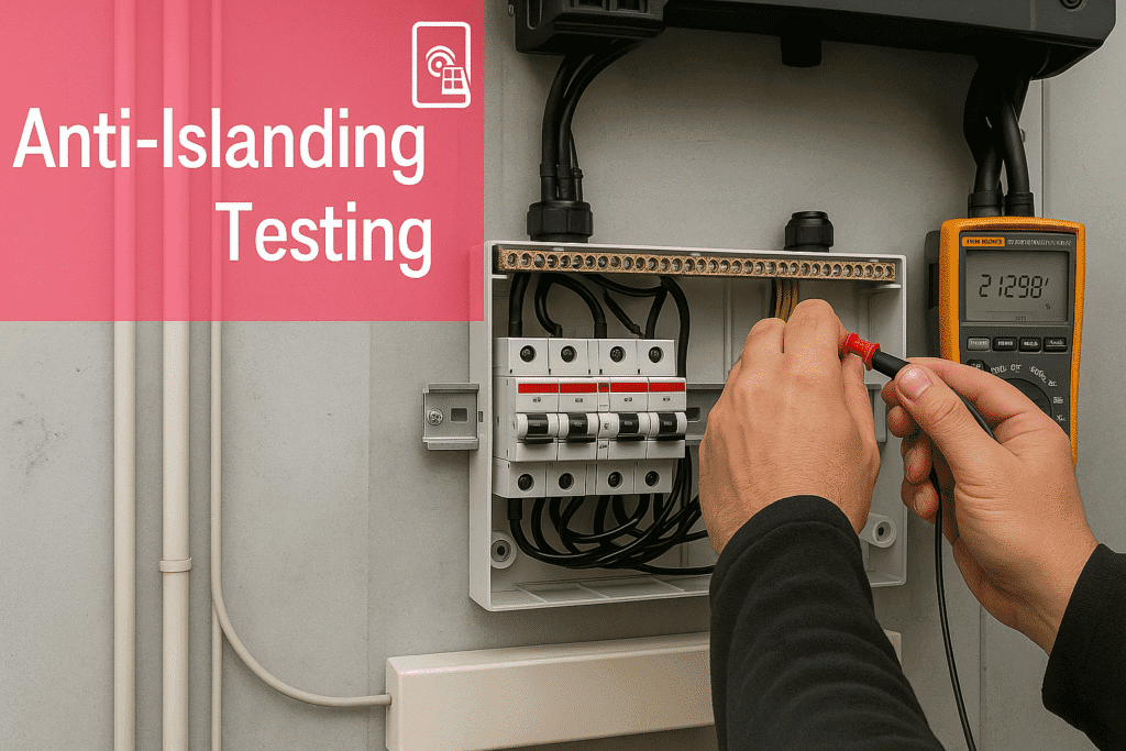
Stage 8: Anti-Islanding Functional Test
Every hybrid solar system commissioned in Nigeria must pass an anti-islanding functional test before handover. This test verifies that the transfer relay opens correctly when the grid fails and that loads continue without interruption.
Test procedure (adapted from IEC 62116 field protocol):
Confirm system is in grid-connected mode with loads running on solar DB circuits
Open the grid input isolator (simulate NEPA failure). Start timing.
The inverter must transition to island mode within 2 seconds. LED lights may flicker once. Computer and router must continue without reset. Record transition time.
Measure voltage at the grid input terminals of the inverter using a multimeter. This reading must be 0V. If it reads 230V, the relay has not opened. This is a critical safety failure. Do not close the commissioning.
Verify the inverter display shows island mode or battery mode (not grid-connected).
Close the grid input isolator (simulate NEPA return). The inverter must wait 30 to 60 seconds before reconnecting. This delay verifies grid stability before reconnection.
Verify the display returns to grid-connected status.
Pass criteria: Transition to island mode in under 2 seconds. Grid input terminals read 0V during island mode. Loads continue without interruption. Reconnection after 30 to 60 second delay.
Fail criteria: Transition takes more than 2 seconds. Grid input terminals still read 230V during island mode (relay fault). Loads drop during transition. Immediate reconnection without stability delay.
Once the system is running correctly in all modes, verify that it is performing at or near designed output.
Solar array performance check:
Measure MPPT input voltage and current on the inverter display at a moment of good irradiance (above 700W/m2, no direct shading). Calculate actual array power:
Array power (W) = MPPT voltage (V) x MPPT current (A)
Compare this against the expected array output at the current irradiance:
Expected output (W) = Array size (kWp) x Irradiance (W/m2) / 1000 x Temperature derating factor
For a 3.5kWp array at 800W/m2 irradiance with a 0.85 temperature factor: Expected = 3,500 x 800 / 1000 x 0.85 = 2,380W
If actual output is below 80% of expected at good irradiance, the array has a fault: a string not contributing, panel mismatch, or MPPT not tracking correctly.
Battery charge rate check:
With the battery below 80% SOC and good solar irradiance, verify the battery charge current on the inverter display. For a 200Ah LiFePO4 battery with a 0.5C charge rate, expected charge current is approximately 100A at 48V. If the charge current is significantly below this and solar is producing well, the BMS CCL may be limiting due to a cell imbalance or temperature issue.
Inverter temperature check:
After 30 to 60 minutes of operation at moderate load, check the inverter operating temperature on the display or monitoring app. For a 5kVA inverter in a Nigerian plant room, operating temperature above 55 degrees C at this stage (before the room heats up in the afternoon) indicates inadequate ventilation.
Pass criteria: Array output within 80% of expected at good irradiance. Battery charging at expected rate. Inverter temperature below 55 degrees C after 60 minutes of moderate load operation.
The final stage of commissioning is not a technical test. It is the setup of the monitoring system and the handover of the system to the owner.
Monitoring setup:
For Deye systems: connect the WiFi logger stick to the home WiFi network through the SolarmanPro app. Verify that live data appears on the dashboard within 5 minutes of connection. Configure the four critical alerts: battery SOC below 25%, inverter fault code, grid disconnection, and zero solar generation during daylight.
For Growatt systems: connect the ShineWiFi-X dongle to home WiFi. Verify live data on ShineServer. Configure alerts in the ShinePhone app.
For Victron systems: connect the Cerbo GX to the home network via Ethernet. Register the system on the VRM portal. Verify data upload in the VRM dashboard. Configure alarms for BMS communication loss, battery low SOC, and inverter overtemperature.
The installer must provide the following documents at handover:
As-built wiring diagram showing actual installed configuration
Component serial numbers (inverter, battery, panels)
Inverter parameter printout or screenshot showing all configured settings
Earth resistance measurement result
Anti-islanding test result with recorded transition time
Monitoring platform login credentials and app setup instructions
Battery manufacturer warranty documentation
Inverter manufacturer warranty documentation
Owner briefing:
Before leaving the site, the installer must walk the owner through:
How to read the inverter display (SOC, operating mode, fault codes)
How to read the monitoring app
What to do if the inverter shows a fault code
What the low SOC alarm means and what action to take
How to safely isolate the system for maintenance
When to call the installer versus when to call the battery or inverter manufacturer
Pass criteria: Monitoring configured and showing live data. All critical alerts set. Handover documentation provided. Owner briefed on system operation.
The Complete Commissioning Checklist at a Glance
Stage
Activity
Pass Criteria
1
Documentation and design verification
Components match design. Labels in place.
2
Visual inspection
No defects. Connections correct. Clearances maintained.
What is hybrid solar system commissioning and why does it matter?
Commissioning is the systematic process of verifying that every component of a hybrid solar system works correctly, every parameter is configured correctly, and every safety function operates as designed. It matters because a system that powers on without faults can still be incorrectly configured, silently damaging the battery, failing to provide backup during NEPA outages, or creating electrical safety hazards. Commissioning closes these gaps before the system is handed over to the owner.
How long does hybrid solar system commissioning take in Nigeria?
A thorough commissioning of a residential hybrid system following all 10 stages takes 3 to 5 hours for a single installer. This includes documentation verification, visual inspection, all pre-energisation electrical tests, configuration verification, the anti-islanding test, performance verification, monitoring setup, and owner handover briefing. Any commissioning completed in under 90 minutes has almost certainly skipped critical stages.
What is the most important thing to check during hybrid solar commissioning in Nigeria?
BMS communication verification (Stage 6) and battery configuration (Stage 5) are the two most important checks for protecting the system’s most expensive component. A hybrid system with BMS communication not active or battery type set to lead-acid profile on a LiFePO4 bank can destroy a N1.65 million to N2.65 million battery bank within 18 months while appearing to operate normally. Read our guide on why most solar battery systems fail before year 2 for the documented failure patterns.
What is the anti-islanding test and how do I perform it?
The anti-islanding test verifies that the hybrid inverter opens its grid relay and transitions to island mode within 2 seconds of grid failure, and that loads continue without interruption during the transition. To perform it: with the system running in grid-connected mode, open the grid input isolator (simulate NEPA failure), time the transition to island mode, verify grid input terminals read 0V during island mode, and verify loads continue running. Close the isolator and verify the inverter waits 30 to 60 seconds before reconnecting.
What documents should I receive at commissioning handover?
You should receive: an as-built wiring diagram, component serial numbers, a screenshot or printout of all inverter parameter settings, the earth resistance measurement result, the anti-islanding test result with recorded transition time, monitoring platform login credentials, and battery and inverter warranty documents. If your installer cannot provide any of these, commissioning is not complete.
My installer said the system is commissioned but never tested anything. What should I do?
Ask for the commissioning documentation listed above. If none exists, request the installer to return and complete the following minimum checks: BMS communication verification (Stage 6), anti-islanding test (Stage 8), battery parameter verification (Stage 5), and monitoring setup (Stage 10). If the installer refuses, use a competent independent engineer to verify the system. The cost of a commissioning verification is far less than the cost of a failed battery bank or an injured NEPA lineman.
How do I verify BMS communication is working on my hybrid system?
On the inverter display, navigate to the battery information screen. If BMS communication is active, you will see real-time cell voltages, BMS-reported temperature, and SOC that changes dynamically with load and charge events. If you see only terminal voltage and a smooth percentage reading that does not respond to load changes, BMS communication is not active. For the diagnostic process and how to fix BMS communication failure, read our articles on inverter-battery communication protocols and SOC drift in lithium battery systems.
Conclusion
Commissioning is not the last step of installation. It is the first step of system operation.
A hybrid solar system handed over without completing all 10 stages is a system operating on hope rather than verified performance. The battery may be configured incorrectly. BMS communication may not be active. The anti-islanding relay may not have been tested. The monitoring may not be set up. The owner may not know how to read a fault code.
Every one of these omissions has a cost. The battery configuration failure costs N1.65 million to N2.65 million in battery replacement. The anti-islanding failure costs a NEPA lineman. The monitoring omission costs the visibility that catches every other problem early.
The 10-stage protocol in this article is the minimum standard for a Nigerian hybrid solar system commissioning. Use it as a checklist. Require documentation for every stage. Do not accept a system handover without it.
I am Engr. Ubokobong Ekpenyong, a solar specialist and lithium battery systems engineer with over five years of hands-on experience designing, assembling, and commissioning off-grid solar and energy storage systems. My work focuses on lithium battery pack architecture, BMS configuration, and system reliability in off-grid and high-demand environments.
Contains information related to marketing campaigns of the user. These are shared with Google AdWords / Google Ads when the Google Ads and Google Analytics accounts are linked together.
90 days
__utma
ID used to identify users and sessions
2 years after last activity
__utmt
Used to monitor number of Google Analytics server requests
10 minutes
__utmb
Used to distinguish new sessions and visits. This cookie is set when the GA.js javascript library is loaded and there is no existing __utmb cookie. The cookie is updated every time data is sent to the Google Analytics server.
30 minutes after last activity
__utmc
Used only with old Urchin versions of Google Analytics and not with GA.js. Was used to distinguish between new sessions and visits at the end of a session.
End of session (browser)
__utmz
Contains information about the traffic source or campaign that directed user to the website. The cookie is set when the GA.js javascript is loaded and updated when data is sent to the Google Anaytics server
6 months after last activity
__utmv
Contains custom information set by the web developer via the _setCustomVar method in Google Analytics. This cookie is updated every time new data is sent to the Google Analytics server.
2 years after last activity
__utmx
Used to determine whether a user is included in an A / B or Multivariate test.
18 months
_ga
ID used to identify users
2 years
_gali
Used by Google Analytics to determine which links on a page are being clicked
30 seconds
_ga_
ID used to identify users
2 years
_gid
ID used to identify users for 24 hours after last activity
24 hours
_gat
Used to monitor number of Google Analytics server requests when using Google Tag Manager
1 minute
You can find more information in our Cookie Policy and .


")


