SOC Drift in Lithium Battery Systems: Why Your BMS and Inverter Disagree
State of charge drift causes lithium batteries to shut down early, overcharge, or show wrong percentages. Learn why BMS and inverter SOC diverge and how to fix it.
Customer calls at 8 PM. Their solar battery system just shut down, inverter display frozen at 22% SOC, error message blinking “Battery Disconnected.” They’re confused and annoyed. Twenty-two percent should mean another two hours of runtime, maybe more. Instead, the system died without warning.
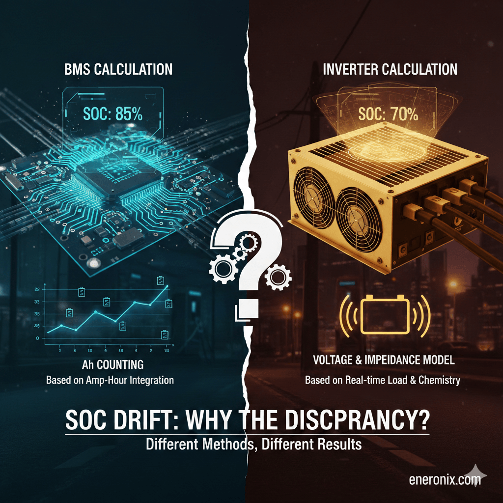
You check the BMS logs remotely. Minimum cell voltage hit 2.78V at shutdown, right at the under-voltage protection threshold. The BMS calculated SOC at 4% when it opened the contactors. The inverter thought it was at 22%.
Eighteen percent divergence. The customer didn’t lose battery capacity, the inverter lost track of what “percent” actually meant.
This happens in thousands of installations. BMS and inverter both calculate State of Charge independently using imperfect methods. Over weeks without proper recalibration, their estimates drift apart. One device thinks the battery is half-full while the other thinks it’s nearly empty. System behavior becomes unpredictable. Customer trust evaporates.
SOC isn’t measured, it’s estimated through integration of current over time, with all the error accumulation that implies. Current sensors are accurate to ±1%, which sounds good until you realize that over 100 kWh of throughput, that’s ±1 kWh of error. For a 10-kWh battery, you’ve drifted 10% SOC without proper recalibration.
This post explains why SOC divergence is inevitable, how fast it happens, what prevents the automatic corrections that should keep it in check, and how to fix it before customers start complaining about “batteries that die early” or “never reach 100%.” The math is straightforward. The field reality is messier.
TL;DR: SOC Drift in Lithium Battery Systems
The Problem: BMS and inverter calculate State of Charge independently. Without recalibration, their estimates drift apart at ±1% per week. After 2 months, 8% to 15% divergence is common. Result: systems shut down “early” or charge past 100%.
Why It Happens:
SOC isn’t measured, it’s estimated by integrating current over time (coulomb counting)
Current sensors have ±1% accuracy, error accumulates continuously
BMS measures at battery terminals, inverter measures at DC bus (different values)
Different sensors, different data, different algorithms = inevitable divergence
Why Recalibration Fails:
Inverter CVL set below balancing voltage (54.4V vs 56.0V needed)
Current never drops below 1A due to inverter self-consumption
Daily cycling stays between 30% and 80%, never reaches full
Temperature extremes degrade sensor accuracy
The Fix:
Set inverter CVL to 56.0V (3.50V per cell) for automatic recalibration
Or schedule monthly manual top balance: raise CVL to 56.8V, charge at 10A to 20A until cells converge
Monitor divergence weekly, act when it hits 8%
Trust BMS SOC over inverter SOC (it has better data)
Key Numbers:
0% to 3% divergence: excellent
3% to 8%: moderate, recalibrate soon
8% to 15%: significant, recalibrate immediately
Above 15%: severe, urgent action required
Bottom Line: SOC divergence is physics, not a defect. Systems need recalibration to reset estimates to known truth (100% full). Enable it by setting CVL correctly, or schedule it manually. Check weekly, fix at 8%, not at 15% when customers complain.
SOC Isn’t Measured. It’s Estimated.
There’s no SOC sensor. You can’t weigh the battery to see how much lithium moved from anode to cathode. You can’t count electrons directly. State of charge is calculated from indirect measurements, and all calculations accumulate error.
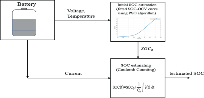
What we actually measure: current (amps in and out), voltage (pack level and individual cells), temperature, and time. From these four inputs, both BMS and inverter attempt to estimate how much energy remains as a percentage of total capacity.
Two estimation methods exist. Coulomb counting integrates current over time. Measure 50A charging for one hour, add 50Ah to the running total. Discharge 30A for two hours, subtract 60Ah. Calculate percentage: current Ah divided by total capacity x 100. This works in theory but requires perfect current measurement. At ±1% sensor accuracy, error compounds with every amp-hour of throughput.
Voltage based lookup measures rested voltage after 10+ minutes of no current and compares against a voltage to SOC curve for the chemistry. This works at extremes (very full shows 3.50V per cell, very empty shows 3.0V) but is useless in the middle. LFP sits at 3.20 to 3.30V from 20% to 80% SOC. The curve is too flat to distinguish anything.
Both devices calculate independently. The BMS has its own current sensor at the battery terminals. The inverter has its own sensor at the DC bus, which may include inverter self-consumption and parasitic loads. Different sensors, different calibration, different starting assumptions, different algorithms. They measure the same battery but see different numbers.
Divergence isn’t a bug. It’s inevitable physics. Without periodic recalibration to reset both estimates to a known truth, they drift apart at roughly ±1% per week of typical use. After two months, 8% to 15% divergence is common. After six months without recalibration, the numbers become meaningless.
Coulomb Counting Error
Current sensors in battery systems are typically accurate to ±1%. Hall effect sensors used in most BMS and inverters spec at ±0.5% to ±1.0% under ideal conditions at 25°C. Shunt resistors are better at ±0.2% to ±0.5%, but cost more and generate heat. Either way, every measurement carries error.
One percent sounds negligible until you integrate it over time. At 50A actual current, a sensor reading ±1% shows 49.5A to 50.5A. That’s ±0.5A constant error. Over one hour, you’ve accumulated ±0.5Ah of error. Over a day of cycling 200Ah (100Ah discharge, 100Ah recharge), you accumulate ±2Ah potential error. For a 200Ah battery, that’s ±1% SOC error per day under worst case conditions.
Errors sometimes cancel. If the sensor reads high during charge and low during discharge, the mistakes partially offset. But errors also compound. If the sensor consistently reads 0.5% high, that bias accumulates relentlessly. After one week of 200Ah daily throughput, cumulative error reaches ±4 to 10Ah depending on how errors stack. That’s ±2% to 5% SOC drift.
Real world example from a 10 kWh system cycling 80% to 30% daily. Week one, BMS and inverter agree within 2%. Week four, they’ve diverged 6%. Week eight without any recalibration, divergence hits 12%. The customer notices the inverter showing 50% when morning solar hasn’t started yet, but yesterday it showed 35% at the same time. Nothing is broken. Coulomb counting error accumulated, and without a reset to known truth, it just keeps growing.
Temperature makes it worse. Sensor accuracy degrades outside 15°C to 30°C. Cold winter mornings at 5°C or hot summer afternoons at 45°C push sensors outside their calibrated range. Offset errors (reading 2A when actual current is zero) become significant and accumulate as pure bias.
Why BMS and Inverter Disagree
The BMS and inverter aren’t measuring the same thing the same way, even though they’re connected to the same battery.
The BMS sees individual cell voltages (16 cells for a 16S pack), cell level temperature or temperature zones, pack current via one sensor, balancing status for each cell, and historical capacity data tracking degradation. It calculates SOC primarily through coulomb counting but recalibrates using voltage when cells reach a known state. A sophisticated BMS resets to 100% SOC when all cells hit balancing voltage (3.48V to 3.50V for LFP) with current near zero for 10+ minutes. This is a known full state. The accumulated coulomb counting error gets cleared.
The BMS has one critical advantage: it knows when balancing completes. When cells converge at top voltage, that’s definitively 100%. It can also detect a weak cell limiting capacity and adjust the total capacity estimate downward as the pack ages.
The inverter sees pack voltage (total, not individual cells), DC bus current which may differ from battery current by a few amps due to inverter self-consumption, and ambient or inverter temperature instead of actual cell temperature. Many inverters either trust the BMS reported SOC and just display it, or calculate independently using voltage-based lookup tables. Some do coulomb counting but without cell level data to know when true 100% occurs.
The inverter’s current sensor is measuring at the DC bus. If the inverter draws 3A for its own control circuits and monitoring, and the battery is charging at 47A, the DC bus sees 50A. The BMS sees 47A at the battery terminals. Over 10 hours, that’s a 30Ah difference. The divergence begins immediately and grows continuously.
Different sensors, different data, different recalibration opportunities. After a few weeks, the gap becomes visible. After two months, it’s a problem.
Steps to Resetting SOC
Coulomb counting drift is inevitable. The solution is recalibration: resetting SOC when the battery reaches a defined state where the true charge level is known.
For lithium systems, “full” is the only practical recalibration point. Definition of 100% SOC: all cells at balancing voltage (3.48V to 3.50V for LFP), current below 1A for 10+ minutes. At this condition, cell voltage directly indicates state. The cells are provably full. The BMS resets its SOC calculation to 100%. Coulomb counting error accumulated since the last reset gets discarded.
The “empty” calibration point is too dangerous to use routinely. Defining 0% SOC requires reaching minimum cell voltage (2.50V to 2.80V), which is already approaching damage threshold. Doing this regularly accelerates degradation. Most systems only recalibrate at full and rely on coulomb counting accuracy for discharge.
Recalibration fails in real systems for four reasons. First, CVL set below balancing voltage. If the inverter CVL is configured to 54.4V (3.40V per cell) for longevity but BMS balancing activates at 3.48V per cell, cells never reach balancing voltage. Charging terminates early. The BMS never sees the full condition. Recalibration never triggers. This is extremely common because installers choose conservative CVL without understanding the recalibration dependency.
Second, current never drops to zero. Many inverters have minimum charge current floors of 2A to 5A. Add inverter self-consumption of 2A to 3A. Total: 5A to 8A continuous even when batteries are full. BMS waits for current below 1A. It never happens. No recalibration.
Third, daily cycling never reaches 100%. Systems sized for daily solar usage cycle between 30% and 80% continuously. No full charge means no recalibration opportunity. SOC drifts from the initial estimate indefinitely.
Fourth, inverter minimum SOC settings. If discharge stops at 20% SOC (reserve capacity setting), the battery never approaches empty. No low-end calibration points either, though this matters less since we avoid using empty for recalibration anyway.
Temperature’s Hidden Impact on SOC Accuracy
Temperature affects SOC accuracy in two ways: actual available capacity changes with temperature, and sensor accuracy degrades outside calibrated range.
LFP capacity varies significantly with temperature. A 200Ah cell at 25°C delivers its nominal 200Ah. The same cell at 5°C delivers roughly 170Ah (85% of nominal). At negative 10°C, capacity drops to 140Ah (70%). Hot weather slightly increases capacity: at 45°C you might see 205Ah (102% to 103%). The chemistry’s ion mobility changes with temperature, directly affecting how much energy you can extract.
The SOC calculation problem: BMS calculates SOC assuming 200Ah capacity at all temperatures. User discharges 85Ah in cold weather, thinking they’ve used 42.5% of 200Ah capacity. But 85Ah is actually 50% of the 170Ah available at 5°C. The BMS shows 57.5% SOC remaining. Reality is 50% remaining. Cold weather makes SOC displays optimistic. You think you have more capacity than actually exists at that temperature.
Current sensors also drift with temperature. Hall effect sensors have offset drift of ±50 to 200 microvolts per degree Celsius. At temperature extremes, this translates to ±0.5A to 2A offset error. An offset means the sensor reads 1.5A when actual current is zero. Over 24 hours, that’s 36Ah of accumulated error from offset alone. For a 200Ah battery, that’s 18% SOC error in one day.
Proper temperature compensation requires the BMS to measure cell temperature and adjust both the capacity estimate (use 170Ah at 5°C, not 200Ah) and the current sensor offset based on sensor temperature. Most residential systems skip this. They use fixed 200Ah capacity regardless of temperature. SOC accuracy degrades significantly outside 15°C to 30°C range, exactly when you need accuracy most (cold winter mornings, hot summer afternoons). Sophisticated systems compensate. Budget systems don’t. The difference shows up as customer complaints about “battery dies faster in winter.”
Detecting and Diagnosing SOC Divergence
SOC divergence shows up in four patterns. Premature cutoff: inverter displays 18% to 25% SOC, system suddenly shuts down with “Battery Disconnected” error. The BMS actually reached 3% to 8% SOC and opened contactors to protect cells. Gap of 10% to 20% divergence becomes visible when it causes shutdown.
Extended charging past 100%: inverter shows 100% SOC but charging continues for 30 to 60 minutes. The BMS hasn’t reached balancing voltage yet, actually at 85% to 92% real SOC. Customer sees “charging at 100%” and thinks something is broken. It’s just divergence. The inverter calculation hit 100% early while BMS knows cells aren’t actually full.
Usable capacity appears reduced: new system runs from 100% to 20% giving expected runtime. After six to eight weeks, same discharge pattern gives 15% to 20% less runtime. Cells haven’t degraded (too soon for measurable capacity fade). The real SOC window has shrunk due to divergence. System now operates from 92% real to 13% real (79% usable) while displaying 100% to 20% (80% apparent). Looks like capacity loss but it’s estimation error.
Display mismatch: BMS shows 62%, inverter shows 54%. The 8% divergence is directly visible if you check both displays. This grows over time, confirming drift is happening.
Diagnostic test: compare BMS and inverter SOC at rest. Let the system sit with no load and no charging for two hours minimum so voltage fully settles. Record both SOC values. Calculate divergence as absolute difference. Zero to 3% divergence is excellent. Three to 8% is moderate, recalibration recommended soon. Eight to 15% is significant, recalibration needed immediately. Above 15% is severe, system likely showing usability problems, urgent recalibration required.
Track divergence over time by logging both SOC values daily at the same time (morning before solar starts is ideal). If divergence increases weekly (2%, then 4%, then 6%, then 8%), coulomb counting error is accumulating with no recalibration happening.
Fixing SOC Divergence
Manual top balance charge forces recalibration. Choose a time with minimal loads (evening or night). Temporarily raise inverter CVL to 56.8V (3.55V per cell for 16S LFP). This ensures cells will reach balancing voltage. Reduce charge current limit to 10A to 20A (0.05C to 0.1C for 200Ah cells). Slow voltage rise gives balancing time to work.
Initiate charging from wherever SOC currently sits. Monitor cell voltages as charge proceeds. Charging continues until pack voltage reaches 56.8V. Current naturally tapers below 1A as cells fill. Cell voltages should converge to 3.52V to 3.55V with spread under 30mV. Wait 30 to 60 minutes at this voltage with current under 1A. This allows balancing to complete and gives BMS time to recognize the full condition.
Verify recalibration occurred. Check BMS display, should now show 100% SOC. Check cell voltage spread, should be under 30mV. Check inverter, should have updated to 100% if trusting BMS SOC. Return CVL and charge current to normal operating values. Frequency: monthly for systems without automatic recalibration, quarterly for verification on systems that should be recalibrating automatically.
Better solution is fixing CVL configuration for automatic recalibration. Set inverter CVL to 56.0V (3.50V per cell, at or above the 3.48V balancing threshold). Every daily charge reaches balancing voltage. Recalibration happens automatically without intervention. Trade off is slightly higher voltage stress (3.50V versus 3.45V conservative charging), costing roughly 10% to 15% cycle life. You get 3,000 cycles instead of 3,500 cycles. Still excellent for LFP, and SOC accuracy is maintained automatically.
Alternative: weekly scheduled top balance if inverter supports scheduling. Daily CVL stays at conservative 55.2V. Every Sunday at 2 AM, inverter raises CVL to 56.8V for one charge cycle, then returns to 55.2V. Best of both: conservative daily charging plus weekly recalibration. Requires sophisticated inverter with automation capability. Must verify automation is working by checking logs monthly.
How to Ensure Long-Term SOC Accuracy
Automated daily logging prevents problems before customers notice. Log BMS SOC and inverter SOC at the same time every day, ideally 8 AM before solar production starts. Calculate divergence as the absolute difference between the two values. Log cell voltage spread (maximum cell voltage minus minimum cell voltage). These four data points tell you everything.
Weekly review catches trends early. Is divergence growing linearly week over week? If you see 2%, then 4%, then 6%, then 8% over four weeks, coulomb counting error is accumulating with no recalibration occurring. Action required: fix recalibration configuration or schedule manual top balance.
Has recalibration occurred? Check BMS logs for SOC reset to 100% events. Should happen at least weekly for daily cycling systems. If no reset events appear in two weeks or more, recalibration isn’t working. Investigate CVL settings and current taper behavior.
Is cell voltage spread increasing? Growing spread (30mV to 80mV to 120mV over months) indicates balancing problems, which relates directly to recalibration. Balancing and recalibration both require the same conditions: cells at balancing voltage with low current. If one fails, the other probably fails too.
Monthly actions keep the system healthy. If divergence exceeds 8%, schedule manual recalibration within one week. If no automatic recalibration occurred in four weeks, investigate and fix the root cause (CVL too low, current never drops to zero, daily cycling doesn’t reach full). Review logs for patterns. Does divergence reset to zero after certain events (weekend when usage patterns change, sunny day when battery fully charges)?
Seasonal adjustments matter. Cold weather reduces available capacity 15% to 30%. SOC displays become optimistic in winter. Inform customers this is normal behavior, not a problem. Hot weather increases current sensor drift. Recalibrate more frequently in summer, weekly instead of monthly. Verify temperature compensation is working if BMS supports it. These simple monitoring practices catch SOC problems months before they become customer complaints.
Conclusion
SOC cannot be measured directly. Coulomb counting accumulates error at roughly ±1% per 100 kWh of throughput. For typical residential systems cycling 200Ah daily, that translates to potential 5% to 10% divergence per month without recalibration. Voltage based SOC estimation doesn’t work for LFP because the discharge curve sits flat at 3.20V to 3.30V from 20% to 80% SOC. Too flat to distinguish anything useful.
BMS and inverter calculate SOC independently using different sensors, different data, different algorithms. The BMS has cell level voltages and knows when balancing completes. The inverter has only pack voltage and DC bus current. Divergence between their estimates is inevitable, not a defect. The question isn’t whether they’ll diverge, but how fast and whether recalibration catches it before customers notice.
Practical approach: understand that 3% to 5% divergence is normal and acceptable. Enable automatic recalibration by setting CVL at or above balancing voltage (56.0V for 16S LFP). Or schedule manual top balance monthly if you prefer conservative daily CVL. Monitor divergence trends weekly. Catch problems when divergence hits 8%, not when customers complain at 15%.
Trust BMS SOC over inverter SOC. The BMS has better data (cell voltages, balancing status, temperature at cells). Configure the inverter to display BMS SOC directly rather than calculating its own. This eliminates visible divergence even if the inverter’s internal calculation drifts.
Set customer expectations correctly. SOC is an estimate, not a measurement. Three to 5% variance between displays is normal physics. Monthly recalibration maintains accuracy within acceptable range. Cold weather reduces displayed accuracy because available capacity actually drops. This is chemistry, not a system problem.
The difference between a functional system and a frustrating one: functional means SOC divergence stays under 8%, recalibrates automatically or on schedule, customer understands it’s an estimate. Frustrating means divergence exceeds 15%, no recalibration, customer thinks the battery is defective. For the complete picture of how BMS and inverter communication affects system behavior, see the full guide on inverter battery communication protocols.
I am Engr. Ubokobong Ekpenyong, a solar specialist and lithium battery systems engineer with over five years of hands-on experience designing, assembling, and commissioning off-grid solar and energy storage systems. My work focuses on lithium battery pack architecture, BMS configuration, and system reliability in off-grid and high-demand environments.
Contains information related to marketing campaigns of the user. These are shared with Google AdWords / Google Ads when the Google Ads and Google Analytics accounts are linked together.
90 days
__utma
ID used to identify users and sessions
2 years after last activity
__utmt
Used to monitor number of Google Analytics server requests
10 minutes
__utmb
Used to distinguish new sessions and visits. This cookie is set when the GA.js javascript library is loaded and there is no existing __utmb cookie. The cookie is updated every time data is sent to the Google Analytics server.
30 minutes after last activity
__utmc
Used only with old Urchin versions of Google Analytics and not with GA.js. Was used to distinguish between new sessions and visits at the end of a session.
End of session (browser)
__utmz
Contains information about the traffic source or campaign that directed user to the website. The cookie is set when the GA.js javascript is loaded and updated when data is sent to the Google Anaytics server
6 months after last activity
__utmv
Contains custom information set by the web developer via the _setCustomVar method in Google Analytics. This cookie is updated every time new data is sent to the Google Analytics server.
2 years after last activity
__utmx
Used to determine whether a user is included in an A / B or Multivariate test.
18 months
_ga
ID used to identify users
2 years
_gali
Used by Google Analytics to determine which links on a page are being clicked
30 seconds
_ga_
ID used to identify users
2 years
_gid
ID used to identify users for 24 hours after last activity
24 hours
_gat
Used to monitor number of Google Analytics server requests when using Google Tag Manager
1 minute
You can find more information in our Cookie Policy and .


")


")


