Generator Sizing for Off-Grid Solar Systems: Integration & Hybrid Operation Guide
Generator sizing for off-grid solar — AC input limit calculations, PowerAssist setup, run time optimisation, and the power quality test most installers skip.
Every evening at 19:47, the generator started automatically. Every evening at 20:19 to 20:22, it stopped. The Cerbo GX log showed the generator running for 85 to 95 seconds on each automatic start before the Multiplus-II dropped the AC input and returned to inverter mode. The battery state of charge at the end of each generator run was within 1 percent of where it had been at the start. The generator was consuming fuel, accumulating hours, and delivering nothing.
The installer who configured the system had set the AC input current limit correctly at 10A and verified the 5kVA generator’s rated output against the combined load calculation. What he had not done was measure the generator’s output voltage at the Multiplus-II’s AC input terminals under the combined load the Multiplus-II placed on it at the moment of transfer. The generator, a low-cost conventional unit with a brush AVR and a mechanical governor, produced 231V at no-load and sagged to 187V within two seconds of accepting the full combined load. The Multiplus-II’s AC input acceptance window has a lower voltage limit of 180V.
The generator was accepted at 187V, which sits just above the rejection threshold, but the Multiplus-II’s internal monitoring flagged the sustained low-voltage condition as an unstable source and dropped the input after 85 seconds to protect the battery from the degraded charge quality.
The root cause was not the AC input current limit. It was a generator with inadequate voltage regulation under load a power quality problem that is only detectable by measuring voltage at the inverter terminals under the actual combined load. This post establishes the complete framework for generator integration: sizing, power quality verification, auto-start configuration, hybrid operating modes, and run time optimisation.
Generator Sizing for Off-Grid Solar Systems (Hybrid)
Generator sizing for a hybrid off-grid system is a three-demand calculation. The total generator demand must cover the peak AC load, the battery charging load, and a starting margin that keeps the combined demand within the generator’s safe operating envelope. The battery charging load is the most commonly omitted term in this calculation, and omitting it produces a generator that is either undersized for the combined demand or oversized for the building load alone.
P_AC_load  = peak AC load at time of generator start (W)

P_charge = battery charge power drawn from generator (W)

0.80 = safe operating factor
The battery charge power drawn from the generator is determined by the AC input current limit configured in the Multiplus-II, not by the charger’s maximum rated current. The Multiplus-II 48/3000/35-32 has a built-in charger rated at 35A DC output, corresponding to an AC input draw of up to 8,050VA at full current. The AC input current limit is the tool that reduces this demand to a manageable level:
The 5kVA generator with the AC input current limit set to 8A produces a combined demand of 3,790W against a 5,000W rating, 75.8 percent loading, within the 80 percent safe operating envelope. The starting margin provides the transient headroom the generator needs to accept the load cleanly when the Multiplus-II transfers to passthrough mode.
AC Input Current Limit, The Critical Configuration Parameter
The AC input current limit caps the total AC current the Multiplus-II draws from its AC input source for both connected AC loads and the battery charger simultaneously. When the total AC input current reaches the configured limit, the Multiplus-II activates PowerAssist mode and begins supplementing the generator output with battery discharge current to serve any additional load demand above the limit without exceeding the generator’s capacity.
The parameter is consistently misconfigured in two ways: not setting it at all, which lets the Multiplus-II draw the full rated charger current from the generator simultaneously with the AC load; or setting it to the generator’s rated output current rather than the safe operating limit. The correct calculation:
I_AC_limit = (P_generator x 0.80 / V_AC) – I_AC_load
For cluster system with 5kVA generator:

I_AC_limit = (5,000W x 0.80 / 230V) - (1,950W / 230V) = 17.4A - 8.5A = 8.9A -> set to 8A (round down)
Setting the limit to 8A rather than 8.9A rounds down conservatively, keeping the combined demand within the safe operating envelope even when the AC load momentarily exceeds the design figure. PowerAssist mode makes the AC input current limit a soft ceiling rather than a hard cutoff. At a boost factor of 2x, a generator operating at its 8A input limit can momentarily serve a load equivalent to 16A of AC current without exceeding its rated output.
Step 3 -> calculate available charging current: safe current - load current
Step 4 -> round down to nearest integer ampere
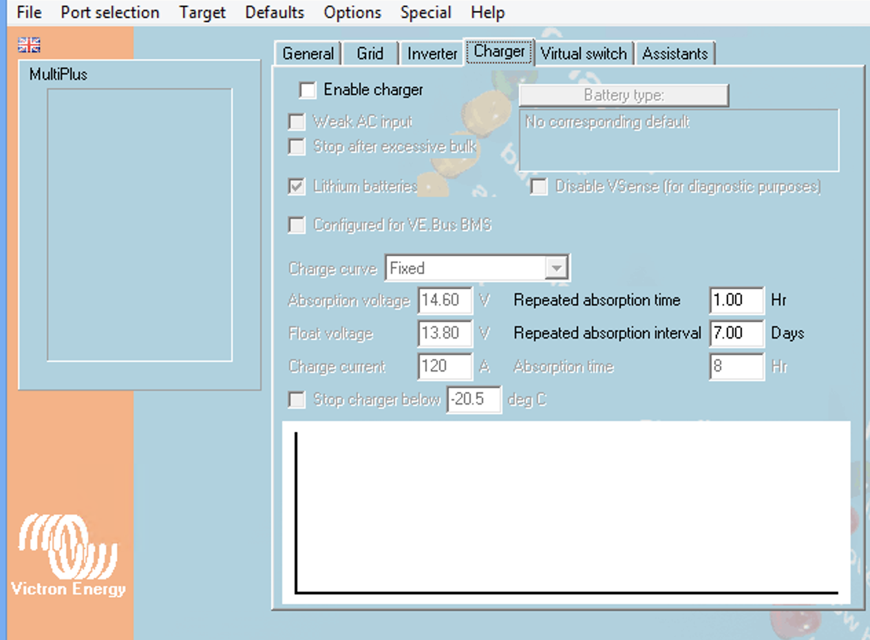
Step 5 -> set in VEConfigure under charger settings: AC input current limit
Step 6 -> verify in Cerbo GX device list: Multiplus-II shows correct limit value
Step 7 -> test under combined load: confirm generator current within safe limit
Generator Power Quality and Acceptance Criteria
The Multiplus-II’s AC input acceptance window is 180V to 265V for voltage and 45Hz to 65Hz for frequency. A generator whose output falls within these limits at the Multiplus-II’s AC input terminals under the full combined load will be accepted as a valid source. The critical qualifier is at the Multiplus-II’s AC input terminals under the full combined load. Generator output voltage varies with the load presented, the quality of the AVR, and the condition of the alternator windings.
The voltage measurement procedure requires a calibrated AC voltmeter connected at the Multiplus-II’s AC input terminals, not at the generator’s output terminals. The cable run from the generator to the inverter produces a voltage drop under load that must be included in the measurement:
Cable voltage drop at 20A through 10m of 2.5mm² cable:
V_drop = I x R = 20A x (0.0175 x 20m / 2.5mm²) = 20A x 0.14Ω = 2.8V
A generator producing 192V at output terminals delivers 189V at inverter input.
-> Accepted initially, rejected after sustained low-voltage monitoring period.
Conventional generators with brush AVRs produce voltage regulation of ±5 to ±10 percent under steady load and ±15 to ±20 percent during load transients. Inverter generators produce voltage regulation of ±1 percent and THD below 3 percent regardless of load, making them the correct specification for installations serving sensitive electronics including computers, servers, and variable speed drives.
Generator Power Quality Acceptance Checklist:
Voltage at inverter terminals under combined load  -> 210V to 250V for stable operation

Voltage measurement point -> Multiplus-II AC input terminals, not generator output

Frequency under full load -> 49.5Hz to 50.5Hz for stable operation

AVR type -> electronic AVR preferred; mechanical governor not acceptable

THD at inverter terminals -> below 5% general loads, below 3% sensitive electronics

Inverter generator preferred -> Honda EU, Yamaha EF, or equivalent for sensitive loads

Cable voltage drop -> calculate and verify within acceptable limit at full load

Test procedure -> measure V and f at inverter terminals under combined load
Automatic Generator Start Configuration
The Cerbo GX’s generator start/stop function provides automatic generator control through a two-wire connection between the Cerbo GX’s dry contact relay output and the generator’s remote start input terminals. The relay closes to start the generator and opens to stop it. Five trigger conditions are available: SoC below threshold, battery voltage below threshold, AC load above threshold, time-based schedule, and manual override. Multiple conditions can be active simultaneously and the generator starts when any enabled condition is met.
The recommended configuration for the cluster system balances fuel efficiency, battery longevity, and generator service life:
Auto-Start Configuration — Cluster System:

Start conditions:
SoC trigger:  start when SoC < 30% for 5 continuous minutes
Voltage trigger: start when battery voltage < 46.4V for 2 continuous minutes

Stop conditions:
SoC target: stop when SoC > 80%
Minimum run time: 30 minutes must elapse before stop condition is evaluated

Failure alarm: VRM alert if generator fails to start after 3 consecutive attempts
The 30% SoC start trigger maintains a minimum one-day autonomy reserve before the generator starts. At the cluster system’s daily discharge of 21,321Wh and usable capacity of 51,120Wh, 30% SoC corresponds to 15,336Wh of remaining capacity — sufficient to serve one full worst-case day before depletion.
The 30-minute minimum run time is the most important stop condition parameter and the one most consistently omitted. Without it, the Cerbo GX may stop the generator within 10 to 15 minutes on a system where solar is producing significant power at the time of generator start. Short-cycling accumulates start wear at many times the rate of a sustained run and consumes more fuel per kWh delivered because the generator spends a disproportionate fraction of its run time in the inefficient warm-up phase.
Auto-Start Configuration Checklist:
SoC start trigger -> 30% SoC for 5 continuous minutes
Voltage start trigger -> 46.4V for 2 continuous minutes (backup condition)
SoC stop target -> 80% SoC
Minimum run time -> 30 minutes before stop condition evaluated
Manual override -> enabled on GX Touch and VRM portal
Run hour alert -> VRM alert at 240 cumulative hours for oil change reminder
Hour counter reset -> manual reset in Cerbo GX generator menu after each service
Hybrid Operating Modes on the Victron Platform
The Victron Multiplus-II supports four distinct operating modes that determine how it manages the relationship between the AC input source, the battery bank, and the connected AC loads.
Inverter-Only Mode
In inverter-only mode the Multiplus-II operates exclusively from the battery bank. The AC input terminal is either disconnected or disabled in VEConfigure. The solar array charges the battery through the MPPT controller and the inverter serves the loads from the battery. This is the default operating mode for a pure off-grid system with no generator connected and the normal daytime operating condition on the cluster system when the battery is above the generator start threshold.
Passthrough Mode
In passthrough mode the Multiplus-II has accepted a valid AC source at its input terminal and transferred the connected loads to the AC input source. The AC source simultaneously serves the loads and provides power to the built-in charger. The inverter stage is bypassed for the connected loads during passthrough, reducing inverter losses. The charger draws current from the AC source up to the AC input current limit. Passthrough mode is the normal generator operating condition on the cluster system.
PowerAssist Mode
PowerAssist mode activates when the connected AC load exceeds the AC input current limit. The Multiplus-II supplements the generator’s output with battery discharge current, adding inverter output to the generator’s passthrough output to serve the combined load. The generator operates at or below the AC input current limit throughout the PowerAssist event:
PowerAssist Example — Cluster System:
AC input current limit: 8A
Generator provides: 8A x 230V = 1,840W
Running load: 1,950W -> inverter adds 110W from battery continuously
Inverter adds: 6,450W - 1,840W = 4,610W from battery during surge
Battery current during surge: 4,610W / 48V = 96.0A < DCL of 148A -> PASS
Duration: 2 to 3 seconds during soft-start ramp
ESS Mode
ESS mode is the Victron Energy Storage System mode designed for grid-connected hybrid installations. It requires a grid connection and is not applicable to the off-grid cluster system. It is noted here because it appears in VEConfigure alongside the other operating modes and is sometimes incorrectly selected on off-grid installations, producing unexpected behaviour when the inverter cannot detect the grid reference it expects.
Operating Mode Selection Reference:
Inverter-only mode -> normal daytime operation, no generator or below start threshold

Passthrough mode -> generator running, loads served from generator, battery charging

PowerAssist mode -> generator at input limit, inverter supplements for load peaks

ESS mode -> grid-connected hybrid only — do NOT select on off-grid systems
Generator Run Time Optimisation
The generator run time optimisation problem balances three competing costs: the fuel cost of generator operation, the battery degradation cost of deep cycling, and the generator wear cost of frequent starts. The three configuration variables that determine run time behaviour are the SoC start trigger, the SoC stop trigger, and the minimum run time.
Run Time Optimisation Variables:

SoC start trigger effect:
Low trigger (20%) -> fewer starts, deeper discharge, higher battery degradation
High trigger (50%) -> more starts, shallower discharge, lower degradation, more fuel
Optimal (30%) -> balances fuel cost and battery degradation at cluster system DoD

SoC stop trigger effect:
Low stop (60%) -> shorter runs, less fuel per run, more frequent restarts
High stop (90%) -> longer runs, more fuel, fewer restarts, full recharge
Optimal (80%) -> leaves 20% for solar to complete charge next morning

Minimum run time: 30 minutes as established in Section 4
The break-even analysis between fuel cost and battery degradation cost confirms the 30 percent start trigger:

Fuel cost per run cycle:
Generator at 75% load: 1.2L/hr x 0.75 = 0.90L/hr
Minimum run time: 0.5hr
Fuel per cycle: 0.45L x ₦1,400/L = ₦630

Battery degradation cost per deep cycle:
Replacement cost: ₦2,800,000 / 10,000 rated cycles = ₦280 per cycle
At 55% DoD (30% trigger): ~₦420 per cycle (interpolated)
Break-even: fuel saving (₦630) > degradation cost (₦420)
Net saving: ₦210 per event in favour of 30% trigger vs 50% trigger

Run Time Optimisation Reference:

SoC start trigger -> 30% (balances fuel cost and battery degradation)
SoC stop trigger -> 80% (leaves headroom for solar completion)
Minimum run time -> 30 minutes (prevents short-cycling)
Seasonal adjustment -> raise to 35% during harmattan (reduced solar yield)
Rainy season note -> increase minimum run time to 45 minutes in extended overcast
Three-Phase Generator Integration
Three-phase generator integration on the commercial system from Post #16 adds three verification requirements beyond the single-phase framework: phase sequence verification, per-phase AC input current limit configuration, and load balance measurement.
Phase Sequence Verification
The three-unit Multiplus-II configuration in three-phase mode expects the generator to deliver phases in the sequence L1-L2-L3 in standard IEC rotation. A reversed sequence L1-L3-L2 causes all three units to reject the source simultaneously. The Multiplus-II does not produce a specific phase sequence alarm — it simply fails to accept the generator source, indistinguishable from a voltage or frequency rejection without a phase sequence measurement. Phase sequence verification requires a phase sequence indicator connected at the Multiplus-II AC input terminals before the generator is started under load. A reversed sequence is corrected by swapping two phase connections at the generator terminal block.
Per-Phase AC Input Current Limit
The AC input current limit on a three-phase system is configured independently per unit in VEConfigure. Each unit’s limit governs the current drawn from its assigned phase:
Per-phase AC input limit for commercial system (8kVA generator):
Generator safe current per phase: (8,000VA / 3 / 230V) x 0.80 = 9.27A
Phase A: load 5.7A, available for charging: 9.27 - 5.7 = 3.57A -> set to 3A
Conclusion: load asymmetry requires generator sized for Phase C peak, not average.
Phases B and C rely on PowerAssist during generator operation.
Load Balance Measurement
After configuring per-phase input limits and starting the generator, AC current on each phase must be measured at the Multiplus-II AC input terminals under the actual building load. A phase imbalance above 20 percent between the most and least loaded phase indicates load distribution requires adjustment.
Three-Phase Generator Integration Checklist:

Phase sequence check -> verified at inverter input terminals before first start

Phase sequence tool -> rotating disc or LED indicator, mandatory commissioning equipment

Reversed sequence fix -> swap two phase connections at generator terminal block

Per-phase input limit -> calculated and set independently per unit in VEConfigure

Load balance measurement -> AC current per phase measured under combined load, imbalance < 20%
The Cerbo GX accumulates generator run hours automatically through the start/stop relay connection, incrementing a cumulative hour counter each time the relay closes and stopping when it opens. This provides the data for maintenance scheduling without requiring the client to track hours manually, which on a system with automatic generator start produces a run hour accumulation that no client reliably tracks without a dedicated instrument.
Configuring VRM alerts at 240, 490, and 990 cumulative hours provides an automatic maintenance reminder before each service interval is exceeded, with a 10-hour buffer that accommodates the time between alert and technician visit. The maintenance log entry in the commissioning documentation after each service creates a traceable history that supports warranty claims on both the generator and the battery bank.
Generator Run Hour Alert Configuration:
240-hour alert -> oil change due within 10 hours; schedule service immediately

490-hour alert -> spark plug, air filter, oil change; schedule combined service

990-hour alert -> full scheduled service including carburetor

Hour counter reset -> manual reset in Cerbo GX generator menu after each service

Service log entry -> record hour counter, date, parts replaced, technician name

Start failure log -> Cerbo GX records failed auto-start attempts; review monthly in VRM
FAQ
What size generator do I need for an off-grid solar system?
Generator sizing requires a three-demand calculation: peak AC load at the time of generator start, battery charging load drawn by the inverter-charger, and a 20% starting margin. The formula is: P_generator = (P_AC_load + P_charge) / 0.80. The battery charging load is determined by the AC input current limit you configure in the inverter, not the charger’s maximum rated current. For a typical Nigerian residential off-grid system with a 1,950W peak load and an 8A AC input current limit, a 5kVA generator is adequate. Undersizing the generator is the most common cause of generator-related system faults.
Why does my generator keep disconnecting from my Victron inverter?
The most common causes are voltage sag below the inverter’s acceptance threshold, frequency instability from an overloaded or poorly maintained generator, or a THD level that exceeds the inverter’s tolerance. The Victron Multiplus-II accepts AC input voltage between 180V and 265V and frequency between 45Hz and 65Hz. Measure voltage at the inverter’s AC input terminals, not the generator’s output terminals under the full combined load. A generator that measures 231V at no-load may sag to 187V under load, which sits dangerously close to the 180V rejection threshold and can cause intermittent acceptance and dropout.
What is the AC input current limit on a Victron Multiplus and why does it matter?
The AC input current limit caps the total current the Multiplus-II draws from its AC source for both connected loads and battery charging simultaneously. When the limit is reached, the inverter activates PowerAssist mode and supplements generator output with battery discharge to serve any additional demand. If the limit is not set, the inverter draws full charger current from the generator on top of the connected load, which typically exceeds the generator’s safe operating envelope and causes voltage sag, overheating, and premature generator wear.
Should I use a conventional generator or an inverter generator with a solar system?
An inverter generator is the correct specification for any solar system serving sensitive electronics. Inverter generators produce voltage regulation of ±1% and total harmonic distortion below 3% regardless of load. Conventional generators with brush AVRs produce ±5 to ±10% voltage regulation under steady load and ±15 to ±20% during transients. The Multiplus-II’s AC input quality monitoring will reject or intermittently disconnect a conventional generator with poor voltage regulation under combined load. Inverter generators are also significantly more fuel-efficient at partial loads, which is most of the time in a solar-supplemented system.
How do I configure automatic generator start on a Victron system?
Automatic generator start is configured in the Victron Cerbo GX under Settings → Generator. Set the SOC start trigger to the battery percentage at which the generator should start, typically 30% for a system designed for 80% depth of discharge. Set the SOC stop trigger to the percentage at which it should stop typically 80% to avoid full-charge inefficiency. Set minimum run time to prevent rapid cycling that accumulates generator starts without meaningful charge, 30 minutes is a practical minimum for most systems. Always test the auto-start sequence manually at commissioning before relying on it for autonomous operation.
What is PowerAssist mode and when does it activate?
PowerAssist mode activates on the Victron Multiplus-II when the AC input current reaches the configured AC input current limit. Instead of allowing the combined load to exceed the generator’s capacity, the inverter supplements generator output with battery discharge current, effectively adding inverter power to generator power for the duration of the peak demand. This means a 5kVA generator with a 2x boost factor can momentarily serve loads equivalent to 10kVA of combined demand without the generator exceeding its rating. PowerAssist is transparent to the connected loads, they see no interruption or voltage variation during the transition.
Conclusion
The generator that ran for 85 seconds every evening and delivered nothing was not a faulty generator. It was a correctly functioning generator connected to a system that had not been verified under the actual load conditions it would encounter in service. The voltage sag that caused the Multiplus-II to reject the source was present on the first day of operation and every day thereafter. It was detectable with a voltmeter and two minutes of measurement time at the inverter’s AC input terminals under the combined load. It was not detected because the commissioning procedure did not include that measurement.
The three parameters that determine whether generator integration works correctly are the AC input current limit, the generator start/stop configuration, and the power quality verification under load. All three must be correct simultaneously. A correctly sized generator with the wrong AC input current limit will overload on the first automatic start. A correctly configured AC input current limit with a generator that cannot maintain voltage under the combined load will produce the 85-second failure cycle from the introduction. A correctly sized and configured system with no minimum run time will short-cycle and accumulate start wear that shortens the generator’s service life regardless of how well it is maintained.
The framework in this post resolves all three failure modes. Apply Section 1 to size the generator against the combined demand. Apply Section 2 to configure the AC input current limit correctly. Apply Section 3 to verify power quality at the inverter terminals under load before commissioning sign-off. Apply Section 4 to configure auto-start with the correct SoC trigger, stop condition, and minimum run time. The generator that was delivering nothing will deliver reliably.
In the next post we examine the most common off-grid system mistakes across design, installation, and commissioning — a consolidated field guide to the errors that produce callbacks, warranty disputes, and premature component replacement.
I am Engr. Ubokobong Ekpenyong, a solar specialist and lithium battery systems engineer with over five years of hands-on experience designing, assembling, and commissioning off-grid solar and energy storage systems. My work focuses on lithium battery pack architecture, BMS configuration, and system reliability in off-grid and high-demand environments.
Contains information related to marketing campaigns of the user. These are shared with Google AdWords / Google Ads when the Google Ads and Google Analytics accounts are linked together.
90 days
__utma
ID used to identify users and sessions
2 years after last activity
__utmt
Used to monitor number of Google Analytics server requests
10 minutes
__utmb
Used to distinguish new sessions and visits. This cookie is set when the GA.js javascript library is loaded and there is no existing __utmb cookie. The cookie is updated every time data is sent to the Google Analytics server.
30 minutes after last activity
__utmc
Used only with old Urchin versions of Google Analytics and not with GA.js. Was used to distinguish between new sessions and visits at the end of a session.
End of session (browser)
__utmz
Contains information about the traffic source or campaign that directed user to the website. The cookie is set when the GA.js javascript is loaded and updated when data is sent to the Google Anaytics server
6 months after last activity
__utmv
Contains custom information set by the web developer via the _setCustomVar method in Google Analytics. This cookie is updated every time new data is sent to the Google Analytics server.
2 years after last activity
__utmx
Used to determine whether a user is included in an A / B or Multivariate test.
18 months
_ga
ID used to identify users
2 years
_gali
Used by Google Analytics to determine which links on a page are being clicked
30 seconds
_ga_
ID used to identify users
2 years
_gid
ID used to identify users for 24 hours after last activity
24 hours
_gat
Used to monitor number of Google Analytics server requests when using Google Tag Manager
1 minute
You can find more information in our Cookie Policy and .


")

")

")
")