How to Size a Hybrid Solar System: The Complete Engineering Guide for Nigeria
How to size a hybrid solar system: the complete 6-step engineering methodology for Nigerian conditions, with worked formulas, real numbers, MPPT string design, cable sizing, and the mistakes that cause 80% of system failures.
Here is how most Nigerian hybrid systems get sized.
An installer visits the site. The client says they want a 5kVA system. The installer quotes a 5kVA inverter, a battery that fits the budget, and enough panels to fill the roof space available. The system is installed, commissioned, and handed over.
Six months later, the battery depletes at 2am instead of 6am. The inverter trips every afternoon when the fridge and freezer compressors start simultaneously. During July, the battery never reaches 100% SOC. The owner calls to complain. The installer says the system is working correctly.
The system is not working correctly. It was sized backwards.
Every component in a hybrid solar system is derived from the one before it in the correct design sequence. If you start with the inverter, you have no basis for the derivation. You are guessing. And in a system that costs N3 million to N12 million, guessing costs real money.
This article gives you the correct sequence: six steps, in the correct order, with the formulas, the worked numbers for a real Lagos home, the MPPT string design that most installers never verify, the cable sizing that most proposals never include, and the three errors responsible for 80% of Nigerian hybrid system failures.
Before any formula, you need four numbers. Everything else is derived from them.
The four numbers that drive every sizing decision:
Daily energy demand (kWh/day): total energy consumed across all loads in 24 hours
Peak simultaneous load (W): maximum wattage running at the same time
Backup autonomy target (hours): how many hours the battery must cover without solar or grid
Location PSH (hours): peak sun hours for your specific Nigerian location and season
Any installer who cannot tell you what these four numbers are for your specific home has not done a real design. They have done a guess dressed up as a proposal.
System Voltage Selection: Why 48V Is Non-Negotiable for Hybrid
Before sizing a single component, you must establish the system voltage. This decision affects cable cost, battery configuration, BMS communication, and long-term system performance. It is not a preference. It is an engineering constraint.
The physics: Power = Voltage x Current. For the same power output, lower voltage means proportionally higher current. Higher current means larger cables, more resistive heat loss, and more voltage drop between components.
At 1,000W output, the current through the battery cables is:
12V system: 83A
24V system: 42A
48V system: 21A
A 48V system carries one-quarter the current of an equivalent 12V system for the same power output. That quarter-current means the cable cross-section required is one-quarter of the 12V equivalent. In Nigeria at 2026 copper cable prices of N4,500 to N8,000 per metre for 70mm2, the cable cost difference on a 5kVA system is N80,000 to N180,000 for the battery interconnects alone.
The rule is straightforward:
System Size
Correct Voltage
Below 1kVA
12V acceptable
1kVA to 3kVA
24V minimum
3kVA and above
48V required
All hybrid inverters in Nigeria above 3kVA
48V
Every hybrid inverter above 3kVA sold in the Nigerian market (Deye, Growatt SPH, Victron Multiplus-II, Felicity hybrid) is a 48V system. The battery bank must be configured as 48V nominal: four 12V batteries in series, or a single 48V LiFePO4 pack.
One specific mistake to avoid: connecting four 12V batteries in parallel instead of series to create a 12V 400Ah bank on a 48V inverter. This is not a 48V system. It is a 12V system trying to feed a 48V inverter through a voltage mismatch. The system will not operate. Beyond the electrical mismatch, parallel battery strings of more than two units create significant BMS balance challenges as the strings age at different rates.
Connect batteries in series for voltage. Connect battery packs in parallel only for additional capacity at the correct system voltage, and only when BMS communication supports it.
Step 1: Load Audit
The load audit is the foundation of every sizing decision that follows. Get it wrong and every subsequent step amplifies the error. Get it right and the entire design falls into place with arithmetic precision.
The load audit has two distinct outputs: daily energy demand in kWh and peak simultaneous load in watts. These are different numbers that drive different components. Daily kWh drives battery and array sizing. Peak watts drives inverter sizing. Mixing them up is one of the most common sizing errors in the Nigerian market.
Essential Load vs Total Load
This distinction saves money. Significant money.
Your total load is every appliance in the house running at its normal schedule. Your essential load is the subset that must stay on during a NEPA blackout or overnight battery discharge.
A typical Nigerian 3-bedroom home total load might be 8,000W across all appliances. The essential load when stripped to what must run overnight (fans, fridge, freezer, lights, router, TV) is typically 1,200 to 1,500W.
The battery is sized for the essential load, not the total load. Sizing a battery for the total load produces a bank 4 to 6 times larger than necessary. At N200,000 to N250,000 per kWh of LiFePO4, that error costs N1.5 million to N4 million in excess battery investment.
Non-essential loads (electric cooker, washing machine, water heater, electric iron, air conditioner above 1HP) should be scheduled to run during NEPA supply hours or peak solar production hours. They do not belong on the essential circuit.
Running Watts vs Surge Watts
Every appliance with a motor has two power ratings: running watts (what it draws during steady-state operation) and startup surge watts (what it draws for 3 to 5 seconds when the motor first starts).
Compressor motors (refrigerators, freezers, air conditioners, pumps) typically surge to 3 to 6 times their running watts at startup. A chest freezer drawing 200W running may pull 800 to 1,200W for 3 seconds at every compressor startup cycle.
Running watts drives battery sizing and array sizing. Surge watts drives inverter sizing. The inverter must handle the highest single surge event that occurs during island mode operation.
Failing to measure surge watts and sizing the inverter only on running watts is the reason so many Nigerian hybrid inverters trip every afternoon when multiple compressors restart after a thermal cycle.
How to Build the Load Table
List every appliance. For each one record: wattage (from nameplate or measured with a clamp meter), daily hours of use, and whether it is essential or non-essential.
Daily Wh per appliance = Wattage (W) x Daily hours (h)
For appliances with duty cycles (fridges and freezers run their compressor only 30 to 50% of the time), multiply wattage by the duty cycle fraction to get average draw.
Sum all essential appliance daily Wh figures. That is your daily essential load in Wh. Divide by 1,000 for kWh.
For the peak simultaneous load, identify the worst-case scenario: the moment when the most loads are running simultaneously, including a compressor in startup. Add those loads at their surge values. That is your peak load for inverter sizing.
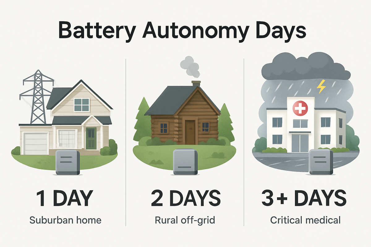
Autonomy is the number of hours the battery must power essential loads with no solar input and no grid supply.
For Nigerian conditions, autonomy is almost always an overnight calculation. Solar stops producing at approximately 6pm. NEPA is unreliable overnight. The battery must bridge the gap from sunset to the point where solar production resumes and NEPA either returns or the battery is fully recharged.
Autonomy targets by Nigerian location type:
Location Type
Minimum Autonomy Target
Urban Lagos, Abuja, Port Harcourt (estate with reasonable DISCO)
10 to 12 hours
Urban locations with poor feeder (4 to 6 hours DISCO per day)
12 to 14 hours
Peri-urban and semi-rural
14 to 16 hours
Near-rural with poor DISCO supply
16 to 20 hours
The specific insight most sizing guides miss: autonomy is calculated on the overnight essential load, not the total daily load.
Your overnight essential load is what runs between 6pm and 6am: fans, refrigerators, freezers, lights, router. Not the washing machine. Not the electric kettle. Not the pressing iron. Those run during daylight hours when solar is available.
A Lagos 3-bedroom home may consume 10kWh across the full 24-hour day. The overnight essential portion of that consumption is typically 5 to 6kWh. Sizing the battery for 12 hours of the 10kWh daily total gives you a 15kWh battery requirement. Sizing correctly for 12 hours of the 5.5kWh overnight essential load gives you a 8.25kWh battery requirement. At N200,000 to N250,000 per kWh of LiFePO4, the difference is N1.35 million to N1.69 million in battery cost. Same system. Same performance. The difference is one distinction in the autonomy calculation.
Step 3: Battery Sizing
With the overnight essential load and autonomy target confirmed, battery sizing follows directly.
Formula:
Required battery capacity (kWh) = (Overnight essential load W x Autonomy hours) / 1000 / DoD / Round-trip efficiency
For LiFePO4 at 80% DoD and 97% DC-coupled round-trip efficiency:
Required capacity (kWh) = (Overnight load W x Hours) / 1000 / 0.8 / 0.97
For a 5.5kWh overnight load at 12 hours autonomy: = 5,500 x 12 / 1000 / 0.8 / 0.97 = 66 / 0.8 / 0.97 = 84.9kWh… wait
Correcting: overnight load is energy, not power. Let me express it correctly.
For 5.5kWh of overnight energy required at 80% DoD and 97% efficiency:
Required capacity = 5.5 / 0.8 / 0.97 = 7.08kWh
Round up to 10kWh (48V 200Ah) to provide a buffer for wet season partial recharge days, morning loads before solar ramps up, and occasional extended blackout periods beyond 12 hours.
The DCL Hidden Variable
Battery sizing in kWh is not the only constraint. The battery’s maximum continuous discharge current (DCL, as reported by the BMS to the inverter) must also be verified against the peak simultaneous load.
A 10kWh LiFePO4 battery at 48V with a BMS DCL of 100A delivers a maximum of: 48V x 100A = 4,800W at any instant.
If the peak simultaneous essential load is 5,200W (fans, fridge surge, freezer surge, lights all coinciding), the battery DCL is the actual binding constraint. The inverter will throttle or the BMS will disconnect the battery to protect the cells. The system appears to trip for no reason.
Verification: Peak load (W) / System voltage (V) = Minimum required DCL (A)
If peak load is 5,200W at 48V: minimum DCL = 5,200 / 48 = 108A
If the battery’s DCL is only 100A, select a battery with a higher DCL rating, or add a second battery in parallel to double the available DCL to 200A.
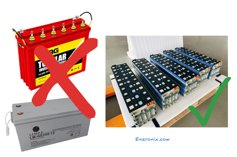
Why LiFePO4 Is the Engineering Choice for Nigerian Hybrid Systems
Three engineering reasons, not marketing:
Voltage stability under load:
LiFePO4 maintains a flat discharge curve between 10% and 90% SOC. For a 48V system, terminal voltage stays between 52.8V and 54.4V across most of the discharge range. Under a 100A load, voltage sag is 1 to 2V. A lead-acid battery at equivalent SOC under the same load sags 6 to 10V. The inverter’s SOC estimate from voltage is far more accurate for LiFePO4 because the voltage signal carries more SOC information per volt of variation.
Thermal stability in Nigerian heat:
LiFePO4 thermal runaway onset temperature is approximately 270°C. Lead-acid thermal runaway can occur above 50°C under overcharge conditions. In a 40°C Nigerian plant room with a misconfigured charger, a lead-acid battery has 10°C of safety headroom. LiFePO4 has 230°C. These are not comparable risk profiles.
Cycle life in Nigerian temperatures:
LiFePO4 rated at 6,000 cycles at 25°C delivers approximately 5,000 cycles at 40°C. Tubular lead-acid rated at 1,500 cycles at 25°C delivers fewer than 400 cycles at 40°C. For a plant room running at 38 to 42°C, LiFePO4 delivers 12 to 15 times more cycles than tubular for the same thermal degradation coefficient. The LiFePO4 premium pays for itself within the first battery replacement cycle.
In a hybrid system, the solar array has two simultaneous jobs: power the daytime loads and recharge the battery. Most Nigerian installers size only for the daytime load. The battery then depends on NEPA to recharge it, which defeats the purpose of an energy-independent system.
Full array sizing formula:
Total daily solar requirement (kWh) = Daytime essential load (kWh) + Battery recharge energy (kWh)
Battery recharge energy = Overnight energy drawn from battery / DC-coupled round-trip efficiency = 5.5kWh / 0.97 = 5.67kWh
Array size (kWp) = Total daily solar requirement / PSH / System derating factor
The Loss Breakdown Table
The system derating factor is not a single number pulled from a textbook. It is the product of multiple real-world loss sources. Here is the explicit breakdown for Nigerian conditions:
Loss Source
International Norm
Nigerian Conditions
Panel temperature derating
5 to 8%
8 to 10% (higher ambient and roof surface temperature)
Soiling (harmattan dust, bird droppings)
2 to 5%
5 to 8% (harmattan season)
Cable and connection losses
1 to 3%
2 to 3%
MPPT tracking efficiency
1 to 2%
1 to 2%
Inverter conversion efficiency
3 to 5%
3 to 5%
Mismatch (panel-to-panel variation)
1 to 2%
1 to 3%
Combined derating factor
0.80 to 0.85
0.75 to 0.80
Nigeria-specific derating is lower than international norms because of higher ambient temperatures and harmattan soiling. A designer using the international 0.85 factor will undersize the array by 6 to 12% and find the battery never fully recharges during July in Lagos.
Use 0.78 as the standard Nigerian derating factor. Use 0.75 for Port Harcourt (higher humidity and soiling risk) and 0.80 for Kano (lower humidity, less soiling but higher temperature).
Peak Sun Hours by Nigerian Location and Season
Location
Dry Season PSH
Wet Season PSH
Design Figure
Kano
6.0 to 6.5h
4.5 to 5.0h
4.5h
Abuja
5.5 to 6.0h
4.0 to 4.5h
4.0h
Lagos
5.0 to 5.5h
3.5 to 4.0h
3.5h
Port Harcourt
4.5 to 5.0h
3.0 to 3.5h
3.0h
Always use the wet season PSH as the design figure. A system sized for Lagos dry season at 5.0h PSH will produce 30% less than designed during July at 3.5h PSH. The battery will never fully recharge. Chronic partial state of charge cycling accelerates battery degradation.
Worked Array Calculation
For the Lagos home: daytime load 3.5kWh + battery recharge 5.67kWh = 9.17kWh total daily solar requirement.
Array size = 9.17 / 3.5 / 0.78 = 3.36kWp
Round to 3.5kWp: seven 500Wp monocrystalline panels.
This is the section that separates a real system design from an estimate. Most Nigerian installers connect panels to the inverter and check that the system turns on. They never verify whether the string voltage is within the MPPT window across the full Nigerian temperature range. The result is a system that shuts down in afternoon heat, clips in dry season cold mornings, or silently damages the MPPT input stage.
A hybrid inverter’s MPPT has three electrical limits:
Vmax: Maximum input voltage the MPPT can accept without damage
Vmin: Minimum voltage at which the MPPT operates
Imax: Maximum input current per MPPT channel
The string must satisfy all three limits simultaneously across the full temperature range your location experiences.
Open-Circuit Voltage at Minimum Temperature (Cold Check)
Panel Voc increases as temperature decreases. In Northern Nigeria (Kano, Abuja) during harmattan mornings, ambient temperature can reach 12 to 15°C. Panel Voc rises above its STC value.
Formula: Voc at Tmin = Voc_STC x [1 + (Tmin – 25) x Voc_tempco]
For a typical 500Wp panel: Voc_STC = 49.5V, Voc_tempco = -0.29%/°C = -0.0029
At 15°C minimum: Voc = 49.5 x [1 + (15 – 25) x (-0.0029)] = 49.5 x 1.029 = 50.9V per panel
For a string of 4 panels in series: 4 x 50.9V = 203.7V
This must be below the inverter’s MPPT Vmax. For a Deye SUN-5K (MPPT Vmax 500V): 203.7V is well within range. For an entry-level inverter with MPPT Vmax 150V: 203.7V destroys the MPPT input stage instantly. One cold harmattan morning. One irreversible failure.
For Lagos and Southern Nigeria where minimum temperature is typically 18 to 22°C, the cold-check voltage rise is smaller but must still be verified.
Minimum Operating Voltage at Maximum Temperature (Hot Check)
Panel Vmp decreases as temperature rises. At 60°C cell temperature (realistic in dry season on a dark roof surface), Vmp drops significantly below the STC value.
Formula: Vmp at Tmax = Vmp_STC x [1 + (Tmax – 25) x Vmp_tempco]
For the same 500Wp panel: Vmp_STC = 41.7V, Vmp_tempco = -0.34%/°C = -0.0034
At 60°C cell temperature: Vmp = 41.7 x [1 + (60 – 25) x (-0.0034)] = 41.7 x 0.881 = 36.7V per panel
For a string of 4 panels: 4 x 36.7V = 146.8V
This must stay above the inverter’s MPPT minimum voltage. For a Deye SUN-5K (MPPT minimum 90V): 146.8V is fine. For an inverter with MPPT minimum 120V and a 3-panel string in this heat: 3 x 36.7V = 110V, which falls below the MPPT minimum. The MPPT shuts off at peak operating temperature every afternoon. The owner sees solar production drop to zero between 12pm and 4pm and assumes a fault.
The real cause is a string too short for the inverter’s MPPT minimum in Nigerian heat. The fix is adding one more panel to the string.
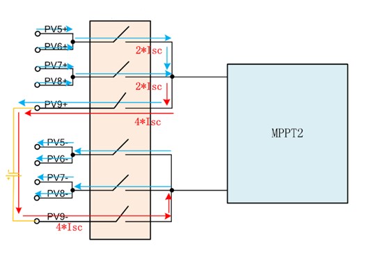
String Current Check
For the 3.5kWp array (seven 500Wp panels), configure as one string of 7 panels or two strings (4 + 3) if the inverter has dual MPPT.
For a single-string configuration: string current = panel Isc = approximately 13.5A for a 500Wp panel.
Verify this against the inverter’s MPPT maximum input current per channel. For Deye SUN-5K: 13A per MPPT. A 500Wp panel with Isc of 13.5A slightly exceeds this. Configure as two strings of 3 and 4 panels on dual MPPT inputs, or verify the exact panel Isc against the inverter spec before purchasing.
Now, with the load audit complete, the battery sized, the array sized, and the MPPT string design verified, the inverter is selected. Step 5 of 6. Not Step 1.
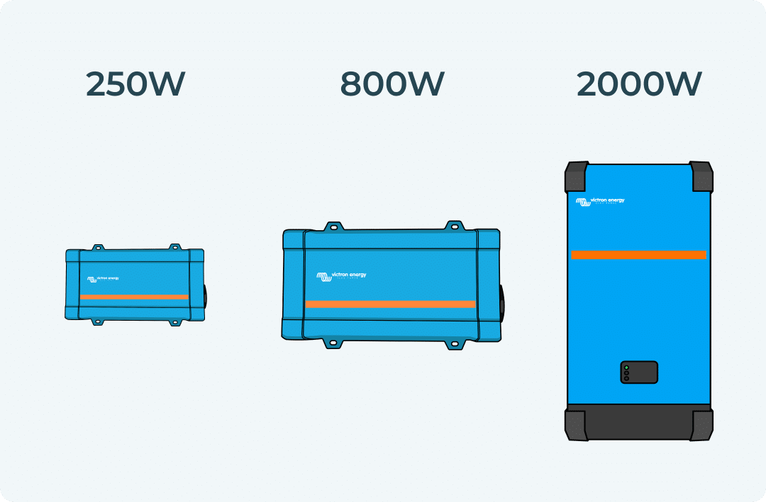
The inverter selection requires four checks. Most Nigerian proposals perform only the first.
Check 1: Continuous Load with Safety Margin
Minimum inverter kVA = Peak continuous essential load (W) x 1.2 / 1000
For a peak continuous essential load of 1,500W: Minimum = 1,500 x 1.2 / 1000 = 1.8kVA
This alone suggests a 2kVA inverter is sufficient. But this check is only the starting point.
Check 2: Temperature Derating
Every hybrid inverter dereates output power above 25°C ambient at approximately 1% per degree.
Formula: Derated output = Nameplate kVA x [1 – (Ambient temp – 25) x 0.01]
For a 5kVA inverter in a 40°C Nigerian plant room: Derated output = 5 x [1 – (40 – 25) x 0.01] = 5 x 0.85 = 4.25kVA
If peak continuous load is 4.0kVA, a 5kVA inverter at 40°C delivers 4.25kVA. Headroom: 250W. Acceptable but thin.
If peak continuous load is 4.5kVA, a 5kVA inverter at 40°C delivers 4.25kVA. The inverter is undersized for that plant room temperature. Select 6kVA or improve ventilation to bring ambient below 35°C.
Rule: Select the inverter based on temperature-derated output, not nameplate rating.
Check 3: Surge Capacity Verification
The inverter’s 5-second surge rating must exceed the highest single motor startup event in the essential load circuit.
For a 1HP submersible pump (startup surge approximately 3,600W to 4,500W), a 5kVA hybrid inverter with a 10kVA surge rating handles the startup. A 3kVA inverter with a 6kVA surge rating does not.
For a 1.5HP non-inverter air conditioner (startup surge approximately 5,500W to 7,500W), even a 5kVA hybrid inverter’s 10kVA surge rating may be marginal. An inverter-type AC with a startup surge of 2,000 to 2,800W is the correct choice for a 5kVA hybrid system.
Use our inverter sizing calculator to verify your inverter selection against all four checks simultaneously.
Check 4: MPPT Window Verification
Already covered in the MPPT string design section. The array’s maximum Voc at minimum temperature must not exceed the inverter’s MPPT Vmax. The array’s minimum Vmp at maximum temperature must stay above the inverter’s MPPT Vmin. Verify before purchasing any component.
This is the most overlooked electrical design element in Nigerian hybrid installations. It is also responsible for the most dangerous field failures.
Undersized DC cables between battery and inverter cause three problems:
Resistive heating that can ignite cable insulation
Voltage drop under load that causes the inverter to read false low battery voltage and switch to grid prematurely
Power loss that reduces effective system output and makes the battery appear to discharge faster than it actually does
Voltage drop formula:
Vdrop = (2 x L x I x ρ) / A
Where:
L = one-way cable length in metres
I = maximum current in amps
ρ = resistivity of copper = 0.0175 Ω.mm2/m
A = cable cross-section in mm2
For a 5kVA inverter at 48V, maximum battery current: I = 5,000W / 48V / 0.94 efficiency = 111A
For a 2-metre run with 35mm2 cable: Vdrop = (2 x 2 x 111 x 0.0175) / 35 = 7.77 / 35 = 0.22V Percentage drop = 0.22 / 48 = 0.46%. Well within the 2% limit.
For the same run with 16mm2 cable (commonly used in Nigeria due to cost): Vdrop = (2 x 2 x 111 x 0.0175) / 16 = 7.77 / 16 = 0.49V = 1.0%. Acceptable.
For a 5-metre run with 16mm2 cable: Vdrop = (2 x 5 x 111 x 0.0175) / 16 = 19.4 / 16 = 1.21V = 2.5%. Exceeds the 2% limit.
At 2.5% voltage drop, the inverter reads battery terminal voltage at 46.8V when the battery is actually at 48.0V. The inverter’s discharge cut-off of 46.4V now triggers at a real battery voltage of 47.6V, cutting off 1.2V of usable discharge range. That corresponds to approximately 15% of the LiFePO4 discharge curve. The system appears to deplete 15% faster than designed.
Recommended cable sizes for Nigerian hybrid installations:
System
Max Current
Up to 2m one-way
Up to 5m one-way
3kVA 48V
70A
25mm2
35mm2
5kVA 48V
115A
35mm2
50mm2
10kVA 48V
230A
70mm2
95mm2
The 2-metre rule:
Keep the battery bank within 2 metres of the hybrid inverter wherever the installation allows. Every metre of additional cable distance is a resistive drop, a heat source, and a potential fault point. Design the plant room layout to minimise this distance before any cable is purchased.
After completing all five sizing steps, two metrics validate that the design is correctly proportioned. If either falls outside the target range, the design needs adjustment before a purchase order is placed.
Self-Sufficiency Ratio
Formula: (Solar energy used + Battery energy used) / Total energy consumed
This measures what percentage of your total energy needs is met by your solar system versus the grid.
Target for Nigerian hybrid: above 60% for a location with 8 to 14 hours of DISCO supply per day.
For the Lagos home: solar covers 3.5kWh of daytime load. Battery covers 5.5kWh overnight. Total: 9.0kWh. Total daily consumption: 10kWh. Self-sufficiency = 9.0 / 10.0 = 90%. Above target.
If self-sufficiency is below 50%, the battery or array is undersized. If it is above 95% and DISCO supply is available, the battery may be oversized relative to realistic grid outage duration.
Battery Cycle Utilisation
Formula: Daily energy throughput / Usable battery capacity
This measures how hard the battery is working daily.
Target: 0.8 to 1.2 cycles per day for LiFePO4 longevity.
For the Lagos home: 5.5kWh drawn nightly / (10kWh x 0.8 DoD) = 5.5 / 8.0 = 0.69 cycles/day. Slightly below the 0.8 lower target. The battery is mildly oversized. Acceptable given the wet season buffer function of the extra capacity.
If cycle utilisation exceeds 1.5 cycles per day, the battery is undersized and cycling too deeply too frequently. Increase battery capacity or reduce the essential load.
Complete Worked Example: Lagos 3-Bedroom Home
Home profile: 3-bedroom in Lekki Phase 1, Lagos. Family of four. No air conditioner on essential circuit. Generator currently running 10 hours per day at N19,000 to N26,000 in daily fuel cost.
Step 1: Load Audit
Appliance
Watts
Duty Cycle
Avg Draw
Hours/Day
Daily Wh
3 ceiling fans
225W
100%
225W
14h
3,150Wh
6 LED lights
60W
100%
60W
8h
480Wh
Chest freezer
200W
40%
80W
24h
1,920Wh
Refrigerator
150W
35%
52W
24h
1,260Wh
Router + decoder
30W
100%
30W
18h
540Wh
LED TV 43″
80W
100%
80W
5h
400Wh
Phone + laptop
100W
100%
100W
3h
300Wh
Miscellaneous
—
—
50W avg
—
500Wh
Total daily
8,550Wh
Daily essential load: 8.55kWh
Overnight essential load (6pm to 6am, 12 hours): Fans 225W x 10h = 2,250Wh, lights 60W x 6h = 360Wh, freezer 80W x 12h = 960Wh, fridge 52W x 12h = 624Wh, router 30W x 12h = 360Wh, TV 80W x 4h = 320Wh
Configuration option: Two strings — 4 panels + 3 panels on dual MPPT inputs.
Cold check (4-panel string at 15°C): 4 x 50.9V = 203.7V. Below 500V Vmax. Safe. Hot check (4-panel string at 60°C): 4 x 36.7V = 146.8V. Above 90V Vmin. Safe. Current check: 13.5A Isc vs 13A MPPT max. Marginally over. Select panels with Isc below 13A, or verify inverter spec allows 5% over Isc tolerance.
Step 5: Inverter sizing:
Peak continuous load: 1,365W Temperature derated 5kVA at 40°C: 4,250W Load utilisation: 1,365W / 4,250W = 32%. Very comfortable. Surge: 1,875W peak surge. Well within 10kVA surge rating of 5kVA inverter. Select: 5kVA 48V hybrid inverter (Deye SUN-5K or Growatt SPH-5000)
Cable sizing (battery to inverter, 2-metre run): Max current = 5,000W / 48V / 0.94 = 111A Using formula for 35mm2 cable, 2m run: Vdrop = 0.22V = 0.46%. Within 2% limit. Select: 35mm2 tinned copper DC cable
The Three Sizing Mistakes Responsible for 80% of Nigerian System Failures
Mistake 1: Sizing Battery for Total Daily Load Instead of Overnight Essential Load
An installer quotes a 15kWh battery for a home with a 10kWh daily total load targeting 12 hours of autonomy. The correct battery based on the 4.9kWh overnight essential load is 6 to 8kWh. The owner buys 15kWh of LiFePO4 at N3 million to N3.75 million. The correct battery costs N1.2 million to N2 million.
Root cause:
Autonomy calculation applied to total daily load instead of overnight essential load. Cost: N1 million to N1.75 million in excess battery investment.
Mistake 2: Sizing Array for Dry Season PSH
An installer uses 5.0h PSH for Lagos (the dry season figure) instead of 3.5h (the wet season design figure). Array is sized at 2.3kWp instead of the correct 3.5kWp.
In July, with 3.5h PSH and the smaller array, daily solar production falls 40% below the recharge requirement. The battery discharges deeper each night and never fully recharges. By week 3 of the wet season, the battery is cycling between 30% and 70% SOC instead of 20% and 100%. Chronic partial state of charge begins degrading the battery.
Root cause:
Dry season PSH used as design figure. Cost: Reduced battery lifespan. Additional panel purchase to correct the array.
Mistake 3: Ignoring Temperature Derating on Inverter Selection
A 5kVA inverter is selected for a peak continuous load of 4.5kVA. The plant room reaches 43°C during harmattan. Derated output: 5 x [1 – (43-25) x 0.01] = 5 x 0.82 = 4.1kVA. The inverter has a 400W deficit against the peak load. It trips daily at 2pm when the generator is off and all essential loads are running simultaneously.
Root cause:
Nameplate rating used instead of temperature-derated rating. Cost: Daily overload trips, premature inverter wear, owner frustration, technician callout costs.
Frequently Asked Questions
What size hybrid solar system do I need for a Nigerian home?
For a 3-bedroom home on essential loads (fans, lights, fridge, freezer, router, TV) in Lagos, a correctly sized system is: 5kVA inverter, 10kWh LiFePO4 battery, 3.5kWp solar array (seven 500Wp panels). For a home adding a 1HP inverter air conditioner, increase the array to 5kWp and consider 15kWh battery for overnight AC use. Always complete the load audit first. The system size follows from your numbers, not from the installer’s available stock. Use our hybrid solar system for home guide for the full worked example.
How do I calculate the battery size for a hybrid system?
Required battery capacity (kWh) = Overnight essential load (kWh) / 0.8 (DoD) / 0.97 (efficiency). The key is using the overnight essential load, not the total daily load. For a Lagos 3-bedroom with a 4.9kWh overnight load, the minimum battery is 6.3kWh. Round up to 10kWh for a wet season buffer. Use our LiFePO4 battery bank calculator for the complete calculation.
What is the correct solar array size for Lagos?
Use Lagos wet season PSH of 3.5h as the design figure. Array size (kWp) = (Daytime load kWh + Battery recharge kWh) / 3.5h / 0.78. For a 10kWh daily home with a 4.9kWh overnight battery draw, the correct array is approximately 3.5kWp. Never use dry season PSH of 5.0h for Lagos. The system will underperform in July and the battery will never fully recharge during the wet season.
How many panels do I need for a 5kVA hybrid system?
It depends on your daily load, not the inverter size. A 5kVA inverter is a load capacity specification, not an energy generation specification. For the Lagos 3-bedroom home in this article, 7 x 500Wp panels (3.5kWp) are sufficient. A different home with a higher daily load may need 10 to 12 x 500Wp panels on the same 5kVA inverter. Complete the load audit and run the array sizing formula. The inverter kVA does not determine panel count.
What cable size should I use between battery and inverter?
For a 5kVA 48V system with a maximum current of 111A and a 2-metre cable run: use 35mm2 tinned copper cable. For runs up to 5 metres: use 50mm2. Never use cable smaller than 25mm2 on a 3kVA 48V system regardless of run length. Undersized battery cables cause voltage drop that makes the inverter switch to grid prematurely and create resistive heating that is a fire risk in enclosed plant rooms.
How do I verify my MPPT string design is correct?
Two checks: Cold check (Voc at minimum temperature must be below MPPT Vmax) and hot check (Vmp at maximum temperature must be above MPPT Vmin). Calculate using panel temperature coefficients from the datasheet. For a 500Wp panel in a 4-panel string in Lagos: cold check gives 203.7V, hot check gives 146.8V. Verify both against your specific inverter’s MPPT specification before purchasing panels or inverter.
What is the difference between sizing for dry season vs wet season?
Lagos dry season PSH is 5.0 to 5.5h. Wet season PSH is 3.5 to 4.0h. An array sized for dry season produces 30% less than designed during July. The battery never fully recharges. Chronic partial state of charge reduces battery lifespan significantly. Always design to wet season PSH for Southern Nigeria. The surplus production in dry season simply clips once the battery is full. Wet season undercapacity has no such natural correction.
Conclusion
Sizing a hybrid solar system correctly is a six-step derivation, not a product selection exercise. Every step depends on the one before it. Start at load audit. End at inverter. Never reverse the sequence.
The four numbers that start the process: daily essential load (kWh), peak simultaneous load (W), backup autonomy target (hours), and location wet season PSH. Every component size in the system is derived from these four inputs using the formulas in this guide.
Two things most Nigerian sizing guides skip that this one covers: MPPT string design verification across the full temperature range, and DC cable sizing with voltage drop calculation. Both are required for a system that performs as designed from day one and continues performing for 10 to 15 years.
The three mistakes to avoid: battery sized on total daily load (fix: use overnight essential load), array sized on dry season PSH (fix: always use wet season PSH for Southern Nigeria), and inverter selected without temperature derating (fix: calculate derated output at your plant room temperature).
I am Engr. Ubokobong Ekpenyong, a solar specialist and lithium battery systems engineer with over five years of hands-on experience designing, assembling, and commissioning off-grid solar and energy storage systems. My work focuses on lithium battery pack architecture, BMS configuration, and system reliability in off-grid and high-demand environments.
Contains information related to marketing campaigns of the user. These are shared with Google AdWords / Google Ads when the Google Ads and Google Analytics accounts are linked together.
90 days
__utma
ID used to identify users and sessions
2 years after last activity
__utmt
Used to monitor number of Google Analytics server requests
10 minutes
__utmb
Used to distinguish new sessions and visits. This cookie is set when the GA.js javascript library is loaded and there is no existing __utmb cookie. The cookie is updated every time data is sent to the Google Analytics server.
30 minutes after last activity
__utmc
Used only with old Urchin versions of Google Analytics and not with GA.js. Was used to distinguish between new sessions and visits at the end of a session.
End of session (browser)
__utmz
Contains information about the traffic source or campaign that directed user to the website. The cookie is set when the GA.js javascript is loaded and updated when data is sent to the Google Anaytics server
6 months after last activity
__utmv
Contains custom information set by the web developer via the _setCustomVar method in Google Analytics. This cookie is updated every time new data is sent to the Google Analytics server.
2 years after last activity
__utmx
Used to determine whether a user is included in an A / B or Multivariate test.
18 months
_ga
ID used to identify users
2 years
_gali
Used by Google Analytics to determine which links on a page are being clicked
30 seconds
_ga_
ID used to identify users
2 years
_gid
ID used to identify users for 24 hours after last activity
24 hours
_gat
Used to monitor number of Google Analytics server requests when using Google Tag Manager
1 minute
You can find more information in our Cookie Policy and .


")

")
")

")


")


