Busbar Cable Fuse Sizing for LiFePO4 Battery.
Of all the mistakes I see in DIY LiFePO4 battery builds, wiring mistakes are the ones that cause the most silent damage. Not the kind that shows up immediately. The kind that shows up 14 months later as a BMS that keeps tripping at 60% SOC with no explanation, or a battery enclosure that runs inexplicably hot.
When you trace these back, the root cause is usually one of three things: a busbar that is too small and has been running with elevated resistance since day one, a cable that is undersized and drops enough voltage under load to confuse the BMS, or a fuse that was sized incorrectly.
This article gives you every calculation, with the complete working, for a typical Nigerian 5kVA 48V off-grid solar installation.
TL;DR
What this covers: how to calculate busbar cross-section, cable gauge, voltage drop, ANL fuse rating, and pre-charge resistor for a DIY LiFePO4 pack. Who it is for: DIY builders and solar installers sizing the power connections for a 48V LiFePO4 battery pack. – Busbar size is based on current density. Cable size is based on both thermal rating and voltage drop. – Total voltage drop across all cables must stay under 0.5V to prevent false BMS UVP trips. – The ANL fuse must be rated above the BMS OCP threshold. It protects wiring, not loads. – The pre-charge circuit limits inverter capacitor inrush. Without it, every inverter startup stresses the BMS. Estimated read time: 14 to 18 minutes.
Why Busbars, Cables, and Fuses Are the Three Non-Negotiable Calculations
A LiFePO4 battery pack is a high-energy, low-impedance source. A fully charged 16S pack at 58.4V can deliver thousands of amps into a short circuit. The protective hardware between the cells and the inverter must be correctly rated to handle normal operating currents safely and to interrupt fault currents reliably.
Busbars connect the cells in series within the pack. An undersized busbar has elevated resistance, which means elevated heat under load and a voltage drop that the BMS reads as a lower cell voltage than is actually present.
This connection between undersized busbars and apparent BMS misbehaviour is covered in our article on signs of a failing BMS.
Cables carry current between the cells, BMS, and inverter. They have two sizing constraints: thermal rating and voltage drop. Both must be within limits simultaneously.
The fuse sits between the battery positive terminal and the BMS, as close to the cells as possible. Its job is to protect the cable in the event of a wiring fault that creates a short circuit path before the BMS can respond.
| KEY TAKEAWAY | Busbar: sized for current density and voltage drop within the pack. Cable: sized for both thermal rating and voltage drop between pack and inverter. Fuse: sized above the BMS OCP threshold to allow the BMS to trip first, while still protecting the cable from a wiring fault. |
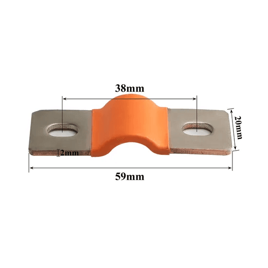
Busbar Sizing
The copper resistivity constant we use throughout is rho = 1.72 x 10⁻⁸ ohm-metres. This is the standard value for annealed copper at 20 degC, consistent with IEC 60228 and ASTM B3 specifications.
The Busbar Voltage Drop Calculation
V_drop = I x R = I x (rho x L / A)
For a 150A current, a 50mm busbar length (0.05m), and a 100mm2 cross-section (100e-6 m2):
R = 1.72e-8 x 0.05 / 100e-6 = 8.6e-6 ohms
V_drop = 150 x 8.6e-6 = 0.00129V per busbar. With 15 busbars in a 16S string: total = 0.019V at 150A. Negligible.
Current Density and Thermal Sizing
In a battery enclosure with limited airflow, use 1.5 A/mm2 as the design limit.
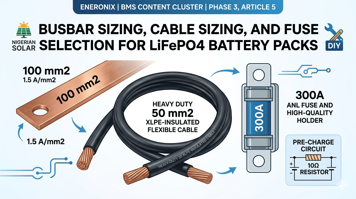
For 150A at 1.5 A/mm2: A = 150 / 1.5 = 100 mm2
For 200A at 1.5 A/mm2: A = 200 / 1.5 = 133 mm2. Use 150 mm2 as the next standard size.
| Current Rating | Minimum Copper Cross-Section | Notes |
| 50A | 25 mm2 (e.g. 5mm x 5mm) | Under 1mV drop per busbar at rated current. Suitable for small 12V or 24V systems. |
| 100A | 50 mm2 (e.g. 5mm x 10mm) | Standard for 3kVA 48V systems. Well within thermal and voltage drop limits at this cross-section. |
| 150A | 75 mm2 (e.g. 5mm x 15mm) | Correct for 5kVA 48V systems with 200A BMS. Use 3mm thick x 25mm wide as an alternative (75mm2). |
| 200A | 100 mm2 (e.g. 5mm x 20mm) | For 5kVA to 8kVA 48V systems. 3mm x 34mm or 5mm x 20mm copper both achieve 100mm2. |
| 250A | 125 mm2 (e.g. 5mm x 25mm) | For 8kVA 48V systems. Standard available: 5mm x 25mm flat copper bar. |
| 300A | 150 mm2 (e.g. 5mm x 30mm) | For 10kVA 48V systems or high-current parallel pack configurations. |
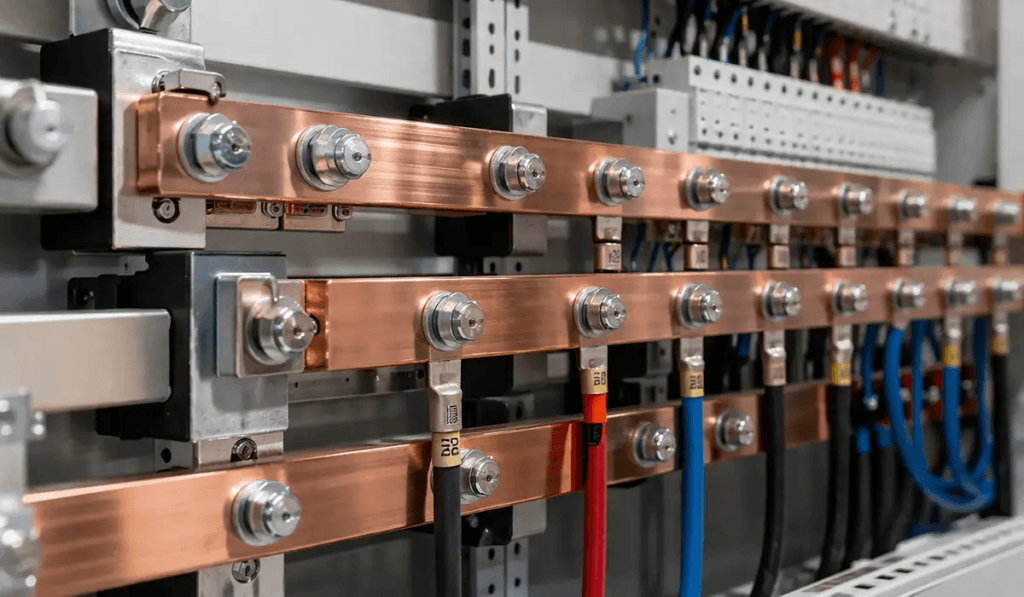
| FIELD NOTE | In the Nigerian market, standard copper flat bar for busbar fabrication is available from electrical material suppliers in Lagos, Kano, and Abuja. For cell junction contacts, cleaning the copper surface with isopropyl alcohol and applying a thin layer of electrical contact grease before assembly provides adequate corrosion protection. |
Cable Sizing
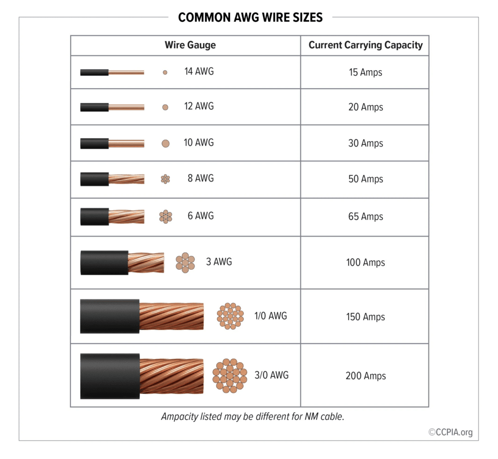
A 35mm2 cable is thermally rated for 150A in free air. But at 150A over a 3 metre cable run, its voltage drop is: V_drop = 150 x (1.72e-8 x 3 / 35e-6) = 0.221V. That drop means the BMS reads voltages 0.221V lower than actual cell voltages. The BMS trips. The customer reports a battery that cuts out too early. The cable was the problem.
The Complete Cable Sizing Formula
Required cross-section A = (I x rho x L) / V_drop_budget
For a battery-to-BMS cable run of 0.5m at 150A with 0.2V budget: A = (150 x 1.72e-8 x 0.5) / 0.2 = 64.5 mm2. Use 70mm2.
| Load Current | Cable Size | One-Way Length | Voltage Drop (V=IxRxL/A) | Assessment |
| 50A | 16 mm2 | 0.5m | 0.027V | Acceptable |
| 100A | 35 mm2 | 1.0m | 0.049V | Acceptable |
| 150A | 50 mm2 | 1.0m | 0.052V | Acceptable |
| 150A | 50 mm2 | 2.0m | 0.103V | Acceptable |
| 150A | 35 mm2 | 1.0m | 0.074V | Acceptable but 50mm2 preferred |
| 150A | 25 mm2 | 1.0m | 0.103V | Marginal. Thermal rating is the real concern. |
| 200A | 70 mm2 | 1.0m | 0.049V | Acceptable for 200A at 1m |
| 200A | 70 mm2 | 3.0m | 0.147V | Acceptable. Total cable run within 0.5V budget. |
| 200A | 50 mm2 | 1.0m | 0.069V | Acceptable for short runs but 70mm2 preferred |
| 250A | 95 mm2 | 1.0m | 0.045V | Correct for 250A at 1m run |
| 300A | 120 mm2 | 1.0m | 0.043V | Correct for 300A at 1m run |
Our dedicated article on DC cable sizing for off-grid solar systems covers the full DC circuit sizing framework.
Temperature Rating:
In a Nigerian generator room at 45 to 50 degC ambient, cable ampacity is reduced. Per IEC 60364-5-52, a 50mm2 XLPE cable rated at 150A at 30 degC carries only 150 x 0.82 = 123A continuously at 50 degC ambient. Size up by approximately one cable gauge from the standard table value.
Cable Insulation: XLPE or EPR, Not PVC
In a Lagos generator room at 45 to 55 degC ambient, PVC-insulated cable rated at 70 degC is not acceptable for pack power cables. Specify XLPE or EPR insulated flexible cable, both rated at 90 degC.
| KEY TAKEAWAY | Size cables for voltage drop AND thermal rating. In Nigerian conditions, apply the IEC 60364-5-52 derating factor for your actual ambient temperature. 50 degC ambient on a 90 degC XLPE cable derates ampacity by 18%. |
Fuse Selection
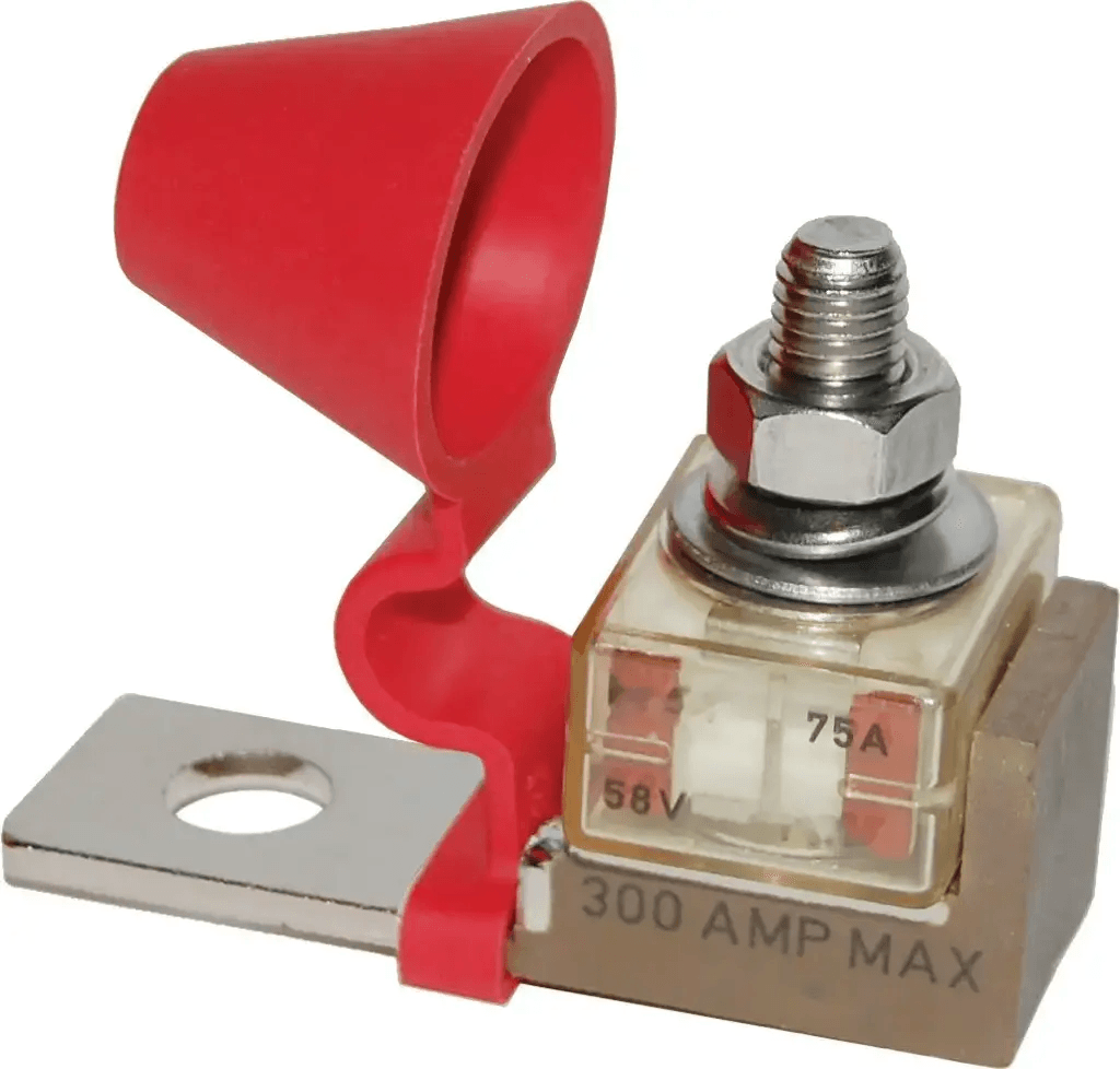
The BMS protects the battery cells. The inverter protects itself. The fuse protects the cable specifically the unfused cable segment between the battery positive terminal and the BMS.
Fuse Rating Calculation
Fuse rating = BMS continuous current rating x 1.25 to 1.5
For a 200A BMS: 200 x 1.25 = 250A minimum. Use a 300A ANL or Class T fuse.
For a 150A BMS: 150 x 1.25 = 187.5A minimum. Use a 200A ANL fuse.
For a 100A BMS: 100 x 1.25 = 125A minimum. Use a 150A ANL fuse.
| BMS Rating | Recommended Fuse Rating | Engineering Rationale |
| 100A BMS | 125 to 150A ANL | Fuse must exceed BMS OCP threshold (typically set at 125% of max current = 125A). Use 150A ANL for margin. |
| 150A BMS | 200A ANL | Standard. 150A BMS on a 5kVA system. 200A ANL provides headroom above the BMS OCP threshold. |
| 200A BMS | 300A ANL | For 5kVA to 8kVA 48V systems. 300A ANL Class T fuse rated for DC battery duty. |
| 250A BMS | 300 to 400A ANL | For 8kVA systems. Use Class T fuse rated for the DC interrupt capacity. |
| 300A BMS | 400A ANL | For 10kVA 48V systems. Verify ANL holder is rated for 400A continuous current. |
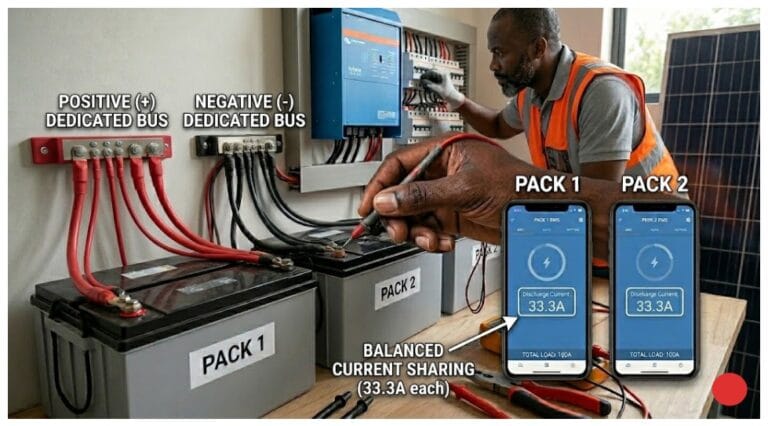
| Parallel packs (3x 100A BMS) | 300A ANL on the main positive bus | Each pack has its own 150A fuse. The main bus fuse protects the combined cable from the bus to the inverter. |
ANL vs Class T vs Other Fuse Types
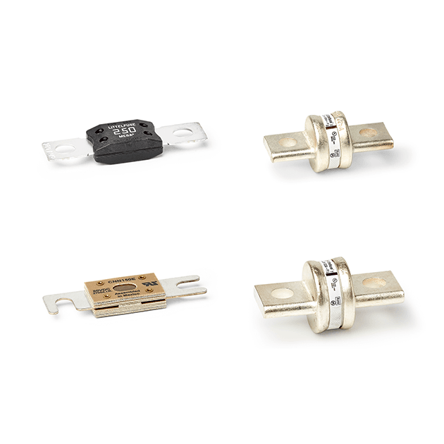
ANL fuses are the standard choice for DC battery pack protection in Nigerian solar installations. Class T fuses provide higher interrupt ratings (up to 20,000A) and are preferred for high-energy packs above 200Ah.
Do not use: automotive blade fuses (too low interrupt rating), glass tube fuses (not rated for DC), or standard mains circuit breakers (designed for AC, will arc under DC fault clearing duty).
| FUSE HOLDER QUALITY | An ANL fuse in a low-quality holder is not a reliable protection system. A corroded or undertorqued ANL fuse holder junction can have 5 to 20 milliohms of resistance, which at 150A produces 0.75 to 3W of heat. Purchase IP-rated sealed ANL fuse holders and torque the fuse terminal bolts to 5 to 7 Nm. |
The Pre-Charge Circuit
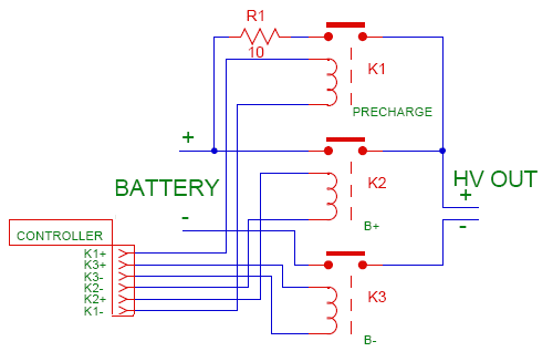
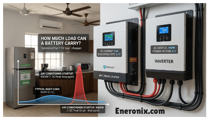
Every inverter contains DC bus capacitors. When the battery circuit is first closed, these capacitors charge from zero to battery voltage. In a well-wired 50mm2 cable system: I_inrush = 58.4 / 0.07 = 834A peak for a few milliseconds.
Without a pre-charge circuit, this spike trips the BMS OCP on every inverter startup, or progressively degrades the BMS MOSFET switches.
Pre-Charge Resistor Sizing
R_precharge = V_battery / I_limit
For V_battery = 58.4V and I_limit = 10A: R = 58.4 / 10 = 5.84 ohms. Use a 10-ohm wirewound resistor. Set the bypass relay timer to 500ms to 1 second.
| KEY TAKEAWAY | Pre-charge takes 2 components (a resistor and a relay) and costs under 2,000 NGN. Without it, every inverter startup creates a current spike that either trips the BMS or degrades the MOSFETs. |
Complete Worked Example: 5kVA 48V Nigerian Off-Grid System
| Parameter | Calculated Value |
| System | 5kVA Deye hybrid, 48V (16S LiFePO4), 200Ah single string |
| Max inverter current | 5,000 VA / 46V = 108.7A |
| BMS rating | 200A (108.7A x 1.25 x 1.15 = 156A; next standard = 200A) |
| Busbar cross-section | 100 mm2 minimum. Use 5mm thick x 20mm wide copper flat bar = 100mm2. |
| Busbar voltage drop | At 150A: V = 150 x (1.72e-8 x 0.05 / 100e-6) = 150 x 0.0000086 = 0.00129V per busbar. Negligible. |
| B+ cable (cell to BMS) | 50mm2 flexible copper, 0.5m run. V_drop = 150 x (1.72e-8 x 0.5 / 50e-6) = 0.026V. Acceptable. |
| P+ cable (BMS to inverter) | 50mm2 flexible copper, 1.5m run. V_drop = 150 x (1.72e-8 x 1.5 / 50e-6) = 0.077V. Acceptable. Total B+ + P+ = 0.103V under 0.5V budget. |
| ANL fuse rating | 300A ANL Class T. Fuse is between B+ terminal and BMS B+ terminal, cable run under 30cm. |
| Cable insulation | XLPE or EPR 90 degC rated. PVC 70 degC is marginal for a Lagos generator room. |
| Pre-charge resistor | 10 ohm, 20W wirewound. Pre-charge relay closes after 500ms. |
| Total voltage drop under max load | 0.026V (B+) + 0.077V (P+) = 0.103V. Well within 0.5V budget. |
Quick Reference
| Calculation | Formula | Variables |
| Busbar cross-section | A = I / J | A = area (mm2), I = current (A), J = 1.5 A/mm2 (enclosed) |
| Busbar voltage drop | V = I x (rho x L / A) | rho = 1.72e-8 ohm-m, L = length (m), A = area (m2) |
| Cable cross-section | A = (I x rho x L) / V_budget | V_budget = 0.5V total for all cable segments |
| Cable voltage drop | V = I x (rho x L / A) | Check that total across all segments is under 0.5V |
| Fuse rating | F = BMS_rating x 1.25 to 1.5 | Select next standard ANL size above calculated value |
| Pre-charge resistor | R = V_battery / I_limit | I_limit = 10 to 20A target. Use 10W wirewound. |
| Pre-charge time constant | t = R x C | C = inverter DC bus capacitance. Set relay to 10x this. |
The Mistakes That Show Up 14 Months Later
| MISTAKE 1 | Using 25mm2 cable for a 150A system. At 150A over a 1.5m run, 25mm2 produces 0.154V drop on that segment alone. UVP trips occur at 40% SOC instead of 20%. Nobody connects it to the cable. |
| MISTAKE 2 | Using PVC 70 degC insulated cable in a Lagos generator room. The insulation begins to soften near the cell terminal junction. By month 18, the insulation has visibly deformed at the crimp lugs. |
| MISTAKE 3 | Installing the fuse between the BMS P+ terminal and the inverter instead of between the B+ cell terminal and BMS. The B+ cable is left entirely unprotected against a fault. |
| MISTAKE 4 | No pre-charge circuit, with BMS OCP threshold raised to accommodate startup inrush. MOSFETs degrade progressively. At month 18 the BMS starts tripping at normal load levels. |
Frequently Asked Questions
What size busbar do I need for a 48V 200Ah LiFePO4 battery pack?
For a 200A BMS on a 5kVA 48V system, the minimum copper busbar cross-section is 100 square millimetres. In practical flat bar dimensions, this is 5mm thick by 20mm wide, or 3mm thick by 34mm wide. The calculation is based on current density limits and voltage drop across the 50mm typical busbar length between cell terminals.
What cable size do I need between my battery and inverter?
For a 5kVA 48V system with a 200A BMS at a 1.5 metre cable run: use 50mm2 flexible copper cable. Voltage drop: 150A x (1.72e-8 x 1.5 / 50e-6) = 0.077V, well within the 0.5V budget. For longer runs or higher currents, increase to 70mm2.
What size ANL fuse do I need for my battery pack?
The ANL fuse must be rated above the BMS OCP threshold to allow the BMS to trip first under overload. For a 200A BMS: use a 300A ANL fuse. For a 150A BMS: use a 200A ANL. For a 100A BMS: use a 150A ANL.
Why is copper better than aluminium for battery busbars?
Copper has a resistivity of 1.72 x 10⁻⁸ ohm-metres, compared to aluminium at 2.65 x 10⁻⁸ ohm-metres. Copper carries 35% more current at the same cross-section for the same voltage drop. Copper also has significantly better corrosion resistance at cell terminal contact points.
What is the voltage drop budget and why does it matter?
The voltage drop budget is the maximum total voltage loss allowed across all power cables between cells and inverter under maximum load. The recommended budget is 0.5V for the entire path. Excess drop causes premature UVP trips because the BMS reads cells as emptier than they are.
Do I need a pre-charge circuit for my inverter?
Yes, for any inverter with DC bus capacitors. Without a pre-charge circuit, the inrush current reaches 200 to 500A briefly. A simple pre-charge circuit using a 10 to 50 ohm 10W resistor with a relay bypass after 500ms limits inrush to 10 to 20A.
Can I use flexible welding cable for battery connections?
Yes. Flexible welding cable is ideal for battery pack power connections. The insulation rating must be 90 degC minimum for Nigerian installation conditions. XLPE or EPR insulated flexible cable at 90 degC rating is the correct specification.
Where exactly should the main fuse be located?
The main fuse must be located at the positive terminal of the battery pack, as physically close to the cells as possible, and before the BMS B+ terminal. Ideal placement: ANL fuse holder mounted directly on or within 30cm of the cell terminal block.
Internal Links Used in This Article
External References
- Copper Development Association
- IEC 60364-5-52 cable ampacity and derating factors
- IEC 60228 copper resistivity specifications
- RVIA DC electrical system standards
- ABYC DC fusing standards
- Prysmian Group cable selection guide for BESS
- Nexans DC cable sizing for PV and battery storage

I am Engr. Ubokobong Ekpenyong, a solar specialist and lithium battery systems engineer with over five years of hands-on experience designing, assembling, and commissioning off-grid solar and energy storage systems. My work focuses on lithium battery pack architecture, BMS configuration, and system reliability in off-grid and high-demand environments.