How to Size a BMS Correctly: Amps, Voltage, and Cell Count Explained
Learn exactly how to size a BMS for any LiFePO4 solar system. Complete worked examples for current rating, cell count, voltage matching, C-rate calculation, and parallel pack sizing for Nigerian installations.
BMS sizing errors are among the most common and most expensive mistakes in Nigerian solar storage installations. Not because the calculations are complex, but because most installers skip them entirely and guess based on what is cheapest or most readily available.
The result of a wrong BMS size is not immediate and dramatic. The system powers up. It works for several months. Then, over 12 to 18 months, the MOSFETs in an undersized BMS degrade from sustained thermal stress, protection functions become unreliable, and the system starts behaving erratically. By the time the customer notices a problem, the damage is done.
This article gives you the complete, step-by-step engineering framework for sizing a BMS correctly. Every parameter has a calculation behind it. We show the full working for each, provide a complete worked example for a typical Nigerian 5kVA off-grid system, and include reference tables for quick sizing across common inverter sizes.
By the end, BMS sizing is a straightforward calculation, not a guess.
Sizing a BMS correctly requires getting three independent dimensions right simultaneously. Getting any one of them wrong produces a system that is either underprotected, unreliable, or incompatible with the rest of the installation.
Dimension 1: Current Rating (Amps)
The BMS current rating determines the maximum charge and discharge current the BMS can handle continuously without degrading its MOSFET switches. The current rating must be matched to the maximum electrical demand the system will place on the battery.
Current rating is the dimension most frequently undersized in the field. The error compounds in hot climates because MOSFET current capacity decreases with temperature, meaning an already marginal rating becomes even more inadequate in Nigerian operating conditions.
Dimension 2: Voltage (Cell Count / S Rating)
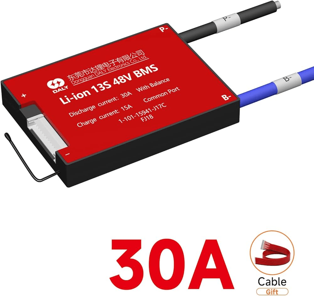
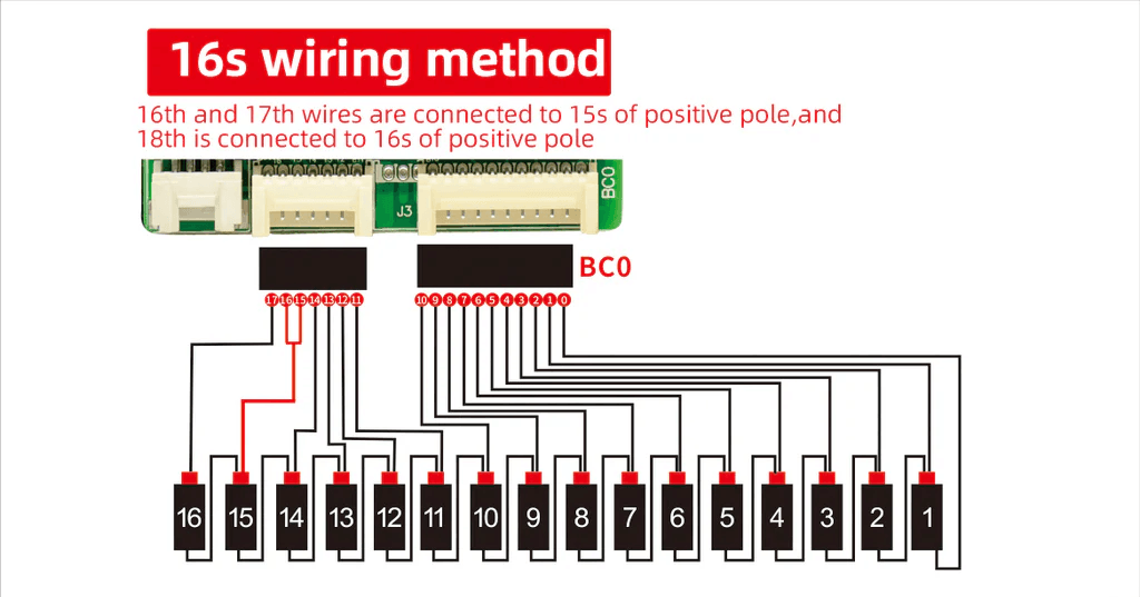
The BMS voltage rating is expressed as its S rating: the number of series cells it can monitor and protect. A 16S BMS monitors 16 cells in series. The S rating must match the series cell count exactly. This is a binary requirement: one cell off in either direction and the BMS cannot function correctly.
The S rating also determines the voltage range the BMS operates over. A 16S LiFePO4 BMS monitors cells across a total voltage range from approximately 40V (16 cells at UVP cutoff) to 58.4V (16 cells at OVP threshold). The BMS electronics must be designed for this voltage range. A 16S BMS cannot be used on a 30S pack regardless of current rating.
Dimension 3: Cell Count Verification
Cell count is distinct from voltage in that it determines not just the S rating but also confirms the physical configuration of the battery pack. A pack described as 48V may contain different cell counts depending on the exact cells used. Standard prismatic LiFePO4 cells at 3.2V nominal require 16 in series for 48V nominal. But some manufacturers use slightly different cell formulations with different nominal voltages, requiring a different cell count for the same nominal pack voltage.
Always verify the actual cell count in the pack rather than assuming from the nominal voltage. Count the individual cells, not the modules.
Cell Count and Voltage:
Before calculating current requirements, the cell configuration must be confirmed. This establishes the pack voltage, the BMS S rating, and the voltage parameters that all subsequent calculations depend on.
Config
Nominal Voltage
Max Charge Voltage
Min Discharge Voltage (per BMS UVP setting)
Pack Energy at 100Ah (Wh)
Typical Application
4S
12.8V
14.6V
10.0-11.2V
48.0-50.4V
12V inverter/charger systems. Small UPS, lighting systems, portable power.
8S
25.6V
29.2V
20.0-22.4V
96.0-100.8V
24V systems. Medium off-grid installations. Some 24V inverter configurations.
16S
51.2V
58.4V
40.0-44.8V
192.0-201.6V
48V systems. The dominant configuration for Nigerian residential and commercial solar. All major hybrid inverters.
24S
76.8V
87.6V
60.0-67.2V
288.0-302.4V
Specialised high-voltage applications. Some commercial-scale inverters.
30S
96.0V
109.5V
75.0-84.0V
360.0-379.5V
96V/100V high-voltage systems. Reduces DC current, allows smaller cable and BMS current rating for the same power.
32S
102.4V
116.8V
80.0-89.6V
384.0-403.2V
High-voltage commercial and grid-scale applications. Less common in Nigerian market.
The 16S Configuration: Why 48V Dominates the Nigerian Market
The 16S LiFePO4 configuration is the standard for Nigerian residential and commercial solar storage for good reason. 48V nominal packs hit the sweet spot of system voltage: high enough to reduce DC current for a given power level (reducing cable size and thermal losses), low enough to stay in the low-voltage category that does not require special high-voltage electrical certifications in most installations, and directly compatible with the entire range of hybrid and off-grid inverters sold in the Nigerian market.
A 16S pack on a 5kVA inverter draws approximately 109A at full load. The same 5kVA on a 12V system would draw approximately 417A, requiring massive cable cross-sections and a BMS rated for current levels that are impractical in a residential installation. The 16S 48V configuration avoids all of this.
For the complete voltage selection decision including the comparison between 48V and high-voltage systems, our article on high voltage vs low voltage inverters covers the engineering tradeoffs in full.
Voltage Compatibility: Matching LiFePO4 to Your Inverter
The BMS cell count directly determines the pack’s voltage range. This voltage range must sit within the inverter’s acceptable DC input window. A mismatch here means either the inverter refuses to charge the battery (pack voltage too high at full charge) or refuses to use it (pack voltage too low at discharge).
Inverter Model
Battery Voltage Class
DC Input Range
LiFePO4 Nominal Voltage
LiFePO4 Max Charge Voltage
Compatibility Notes
Deye SUN-5K-SG03LP1
Low-voltage 48V
42 to 60V
51.2V (16S)
58.4V (16S)
Full compatibility. 16S LiFePO4 is the standard specification for this inverter.
Victron MultiPlus-II 48/5000
Low-voltage 48V
38 to 62V
51.2V (16S)
58.4V (16S)
Full compatibility. Configure absorption voltage to 58.4V and float to 53.6V in VEConfigure.
Growatt SPH5000TL
Low-voltage 48V
40 to 60V
51.2V (16S)
58.4V (16S)
Full compatibility. Set battery type to Lithium and configure charge voltage correctly.
Solis RHI-3.6K-48ES
Low-voltage 48V
40 to 60V
51.2V (16S)
58.4V (16S)
Full compatibility. Same configuration as other 48V hybrid inverters.
Deye SUN-10K-SG04LP3
High-voltage 100-120V
80 to 120V
96V (30S)
109.5V (30S)
30S LiFePO4 required. 16S pack voltage is too low for this inverter’s input range.
Generic 12V inverter/charger
12V
10.5 to 15V
12.8V (4S)
14.6V (4S)
4S LiFePO4. Small capacity systems only.
The most common voltage mismatch in Nigerian installations occurs when an installer uses a 16S LiFePO4 pack with an inverter configured for lead-acid charging parameters. The lead-acid charge voltage for a 48V system is typically 56 to 57.6V. The LiFePO4 16S pack charges to 58.4V. If the inverter is left on lead-acid settings, it undercharges the LiFePO4 pack by 0.8 to 2.4V, reducing usable capacity by 10 to 20% and leaving the cells chronically in a partial state of charge that accelerates sulfation-equivalent calendar aging.
CRITICAL CONFIGURATION
When installing any LiFePO4 battery pack with any inverter, the inverter battery type must be changed from Lead-Acid to Lithium (or to the specific battery brand if communication is configured). The charge voltage, discharge cutoff, and float settings must all be updated for lithium chemistry. Leaving the inverter on lead-acid settings with a lithium battery is one of the most damaging configuration errors in Nigerian solar installations.
Current Sizing:
Current sizing is the most critical BMS specification and the one that requires actual calculation rather than estimation. The following framework gives you the exact steps for any inverter size on any battery voltage.
Step 1: Identify Maximum Inverter DC Current Demand
The maximum DC current demand from the inverter is the inverter’s rated apparent power (VA) divided by the minimum battery voltage at which the inverter operates. The minimum operating voltage for LiFePO4 systems is the inverter’s low battery cut-off voltage, typically set to 44 to 46V for a 16S 48V pack.
The formula is:
Maximum DC Current = Inverter VA Rating / Minimum Battery Voltage
For a 5kVA inverter with a 46V cut-off: 5,000VA / 46V = 108.7A
Note that VA (volt-amps) is used rather than watts because the inverter’s full output capacity in VA represents the worst-case current demand scenario. Using watts would underestimate peak current demand if loads have a power factor below 1.
Step 2: Apply the Derating Margin
The calculated maximum current must be multiplied by a derating factor to establish the minimum BMS continuous current rating. The standard derating factor is 1.25 (25% margin). This margin provides:
Protection against brief peak loads exceeding the calculated maximum (compressor startup, motor inrush)
Buffer for current measurement imprecision in the inverter
Headroom for load growth as the customer adds appliances over time
Partial compensation for temperature derating of MOSFET capacity
Minimum BMS Rating = Maximum DC Current x 1.25
For the 5kVA example: 108.7A x 1.25 = 135.9A
Step 3: Apply Thermal Derating
Standard BMS current ratings are specified at 25 degC ambient temperature. In Nigerian installations where battery enclosure temperatures regularly reach 40 to 55 degC, MOSFET current handling capacity is reduced by a further 15 to 25% depending on the MOSFET technology and PCB thermal design.
For Nigerian conditions, apply an additional 15% thermal derating factor beyond the standard 25% margin:
Nigeria-Adjusted BMS Rating = Minimum BMS Rating x 1.15
For the 5kVA example: 135.9A x 1.15 = 156.3A
Round up to the next standard BMS current rating available in the market. Standard sizes are typically 60A, 80A, 100A, 120A, 150A, 200A, 250A, 300A. For 156.3A, the next standard size is 200A.
Current Sizing Reference Table
Inverter
Battery System
Inverter VA
Min Cut-Off V
Max DC Current
Min BMS Rating (x1.25)
Standard BMS Size
Notes
1 kVA
48V (16S)
1,000
46
21.7A
27.2A
50A
50A BMS. Adequate for the load with good margin.
2 kVA
48V (16S)
2,000
46
43.5A
54.4A
75A
75A or 100A BMS. 100A gives expansion headroom.
3 kVA
48V (16S)
3,000
46
65.2A
81.5A
100A
100A minimum. 150A preferred for startup surge and thermal derating.
5 kVA
48V (16S)
5,000
46
108.7A
135.9A
150A
150A minimum. 200A strongly recommended for Nigerian conditions.
8 kVA
48V (16S)
8,000
46
173.9A
217.4A
250A
250A BMS. Consider split parallel BMS configuration at this scale.
10 kVA
48V (16S)
10,000
46
217.4A
271.8A
300A
300A BMS minimum. High-voltage alternative reduces current significantly.
5 kVA
96V (30S)
5,000
92
54.3A
67.9A
75A
High-voltage advantage: same 5kVA requires only 75A BMS vs 150A on 48V.
10 kVA
96V (30S)
10,000
92
108.7A
135.9A
150A
High-voltage 10kVA uses same BMS rating as 48V 5kVA system.
The High-Voltage Advantage in Current Sizing
The table above demonstrates a significant engineering benefit of high-voltage systems that is often overlooked in the Nigerian market: the same inverter output power requires a dramatically lower BMS current rating at 96V compared to 48V.
A 10kVA system on 48V requires a 300A BMS, which is expensive and represents the practical upper limit of single-BMS configurations in residential applications. The same 10kVA system on 96V requires only a 150A BMS, opening up a much wider range of available, cost-effective BMS options.
After sizing the BMS current rating, a secondary check should confirm that the battery cells themselves can deliver the required current within their rated C-rate. The BMS current rating does not help if the cells cannot physically sustain the demanded current.
C-rate is the current expressed as a multiple of the cell’s Ah capacity. A 100Ah cell at 1C delivers 100A. At 0.5C it delivers 50A. Most LiFePO4 cells are rated for 1C continuous discharge and often higher for brief peak periods.
C-Rate
Description
Current at 100Ah
Current at 200Ah
Current at 400Ah
Current at 1,000Ah
0.2C (5-hour rate)
Conservative discharge. Highest efficiency, lowest heat, longest cell life.
20A
40A
80A
200A
0.5C (2-hour rate)
Standard solar storage rate. Good balance of efficiency and capacity utilisation.
50A
100A
200A
500A
1C (1-hour rate)
Maximum continuous rate for most LiFePO4 cells. Moderate heating. Acceptable for daily cycling.
100A
200A
400A
1,000A
2C (30-minute rate)
High rate discharge. Significant cell heating. Only brief periods recommended. Not suitable for sustained loads.
200A
400A
800A
2,000A
3C+ (under 20 min)
Peak/surge only. 30 seconds or less. Cell stress is high. Many LiFePO4 cells not rated for continuous 3C.
300A+
600A+
1,200A+
3,000A+
C-Rate Verification Calculation
Verify the C-rate of the proposed system by dividing the maximum current demand by the total pack capacity:
C-rate = Maximum DC Current / Pack Capacity (Ah)
For a 200Ah pack with a 5kVA inverter demanding 108.7A maximum: 108.7A / 200Ah = 0.54C
This 0.54C demand is well within the 1C continuous rating of standard LiFePO4 cells and does not create any concern. The cells can sustain this demand indefinitely without thermal stress from C-rate alone.
However, if the system were sized with only 100Ah of battery capacity: 108.7A / 100Ah = 1.09C. This exceeds the standard 1C continuous rating. The cells would run hot, age faster, and the BMS would need to enforce current limits to protect them. The correct solution is to increase battery capacity, not to raise BMS current limits.
The maximum safe charge current calculation for common LiFePO4 pack sizes is worked through in our article: maximum charging current for a 100Ah lithium battery. The same principles apply to discharge current sizing.
Sizing a BMS for Parallel Battery Packs
When multiple battery packs are connected in parallel to increase total system capacity, each pack has its own BMS. The sizing calculation for each individual BMS changes because the current demand is shared across all parallel packs.
In theory, parallel packs share current equally. If two 200Ah packs are connected in parallel, each carries half of the inverter’s 108.7A demand: 54.35A each. Each BMS needs to handle only 54.35A of actual current, giving a minimum rating of 68A per BMS, and a practical size of 100A.
In practice, current sharing in parallel packs is not perfectly equal. Cell differences, internal resistance variation, BMS MOSFET voltage drop variation, and cable impedance differences all cause some packs to contribute more current than others. A 10 to 15% current sharing imbalance is normal. The BMS sizing should account for this.
Pack Configuration
Total Capacity
Max Inverter Current
BMS Specification
Notes
1 pack x 100Ah
100Ah
100A max draw
150A BMS (1 pack)
Simple. One BMS sized for full inverter demand.
2 packs x 100Ah
200Ah
100A max draw
100A BMS per pack (2 units)
Each pack carries 50A nominal share. 100A BMS per pack gives 2x margin. Preferred.
2 packs x 200Ah
400Ah
100A max draw
100A BMS per pack (2 units)
Each pack carries 50A nominal share. 100A BMS per pack is adequate with margin.
3 packs x 100Ah
300Ah
100A max draw
100A BMS per pack (3 units)
Each pack carries 33A nominal share. 100A BMS gives 3x margin. Current sharing monitored via BMS app.
4 packs x 200Ah
800Ah
200A max draw
150A BMS per pack (4 units)
Each pack carries 50A nominal share. 150A BMS per pack. Verify current sharing balance regularly.
PARALLEL PACK WARNING
Never connect parallel battery packs with significantly different states of charge without pre-charging the lower-SOC pack first. Connecting a full pack directly in parallel with a half-charged pack creates a large instantaneous current surge as charge redistributes between them. This surge can trip the BMS OCP protection on both packs and in extreme cases can damage cell terminals, busbars, and the BMS MOSFET switches. Always bring parallel packs to within 0.2V of each other before connecting.
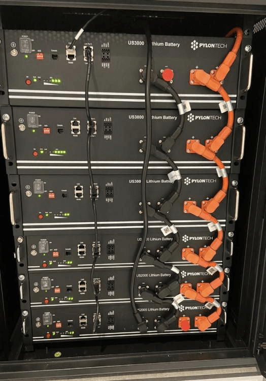
The full engineering guide for wiring and managing parallel battery packs is in our article: how to wire Pylontech batteries in parallel. The same principles apply to DIY parallel packs with external BMS units.
Complete Worked Example: Sizing a BMS for a 5kVA Solar System
The following step-by-step calculation sizes the BMS for a standard Nigerian residential off-grid system: 5kVA hybrid inverter, 48V battery, expected daily load of 15 to 20kWh, Deye inverter brand.
Sizing Step
Value / Decision
Engineering Rationale
Step 1: Define inverter
5kVA hybrid inverter
Deye SUN-5K-SG03LP1
Step 2: Battery voltage
48V nominal (16S LiFePO4)
Standard for this inverter class
Step 3: Cell count
16 cells in series
16S BMS required. Non-negotiable.
Step 4: Max DC current
5,000VA / 46V = 108.7A
Use 46V as minimum cut-off voltage
Step 5: BMS current minimum
108.7A x 1.25 = 135.9A
25% derating margin applied
Step 6: Thermal derating (Nigeria)
135.9A x 1.15 = 156.3A
Additional 15% for hot enclosure conditions
Step 7: Standard BMS size
200A (next standard size above 156A)
150A is borderline; 200A provides safety margin
Step 8: Communication protocol
RS485 Modbus (Deye variant)
Confirm from Deye supported battery list
Step 9: Balancing type
Active balancing, minimum 1A
Daily cycling system, 200Ah+ pack expected
Step 10: Port configuration
Separate-port preferred
Allows solar charging during UVP protection events
Step 11: Temperature sensors
Minimum 2 thermistors
Cell stack + MOSFET board
Step 12: Charge OTP (Nigeria)
Hard cutoff at 50 degC
More conservative than global default of 55-60 degC
JK BMS 200A active balancer series matches this specification
The output of this calculation: a 16S, 200A, RS485 Modbus (Deye protocol), active balancing minimum 1A, separate-port, Bluetooth app BMS with a 50 degC charge temperature cutoff.
In the Nigerian market, the JK BMS active balancer series in the 200A variant (JK-BMS-B2A8S20P or the higher-current variant) matches this specification closely. The specific firmware variant for Deye compatibility should be confirmed with the supplier before purchase.
Accounting for Startup Surge:
Every sizing calculation based on inverter VA rating captures only the steady-state current demand. It does not capture the startup surge that occurs when the inverter first powers up or when it restarts after a shutdown.
Modern hybrid inverters contain large DC bus capacitors on their input stage. When the inverter is energised, these capacitors charge from zero volts to full pack voltage in milliseconds. The charging current is limited only by the circuit resistance of the connecting cables and the BMS MOSFET on-resistance. In a low-impedance circuit with short, large-cross-section cables, this surge can reach 300 to 600A or more for 10 to 100 milliseconds.
Why This Matters for BMS Sizing
A BMS rated at 200A continuous has a short-circuit protection that fires when current exceeds a much higher threshold (typically 500 to 1,000A instantaneously). The startup surge from a 5kVA inverter typically falls between the continuous OCP threshold and the SCP threshold, landing it squarely in the OCP trip range.
The result: every time the inverter starts, the BMS trips. The installer observes the system starting and immediately shutting down. The BMS protection log shows OCP trip at startup. The diagnosis is incorrectly attributed to a faulty BMS when the actual cause is inverter capacitor inrush.
Solutions in Order of Engineering Preference
Pre-charge circuit: A relay and resistor circuit that connects the battery to the inverter through a current-limiting resistor for 100 to 500 milliseconds before closing the main relay. The resistor limits inrush to a manageable level. This is the cleanest solution and is standard practice in well-engineered EV and industrial battery systems.
BMS with configurable peak threshold: Some smart BMS units (JK BMS included) allow a separate peak current threshold and peak duration to be configured. Set the peak threshold above the expected startup surge level with a very short allowed duration (50 to 200ms). Above this duration at peak current, the BMS trips normally.
Slow-start inverter setting: Some inverter models have a configurable DC bus pre-charge time or soft-start setting that reduces the capacitor charging rate. Check the inverter manual for soft-start or pre-charge configuration options.
What not to do: raise the continuous OCP threshold permanently to accommodate startup surge. This removes protection against sustained overcurrent events that are genuinely damaging. The startup surge is a transient design problem, not a reason to weaken continuous protection.
Common BMS Sizing Mistakes and Their Consequences
MISTAKE 1
Sizing BMS current from the inverter’s rated watt output rather than VA rating. For a 5kVA inverter with a 4kW rated power output at 0.8 power factor, using 4,000W / 48V = 83A significantly underestimates the peak current demand. The inverter can draw its full 5,000VA during capacitive or inductive loads. Always use VA for worst-case current sizing.
MISTAKE 2
Not accounting for temperature derating in Nigerian conditions. A 150A BMS sized to the global standard 25% margin is adequate at 25 degC. In a 50 degC battery enclosure, the effective MOSFET capacity is 90 to 115A. The 150A BMS is now operating near or above its thermally-derated limit. The Nigerian-adjusted calculation requires 200A for the same inverter.
MISTAKE 3
Using the same BMS current rating for parallel packs as for single packs. A 200A BMS specified for a single-pack 5kVA system is oversized for each individual pack in a two-pack parallel bank where each pack carries only 55A nominal. The correct specification for the parallel system is a 100A BMS per pack, which is both adequate and more cost-effective.
MISTAKE 4
Not verifying that the cell C-rate supports the BMS current rating. Specifying a 200A BMS for a 100Ah pack allows the BMS to pass 200A through cells rated for 100A maximum. The BMS will not trip (200A is within its rating) but the cells are being pushed to 2C, significantly above their rated 1C continuous limit. The correct solution is to increase pack capacity to match the current demand within the cell C-rate specification.
For the broader context of how sizing errors and misconfiguration lead to premature battery failure in Nigerian installations, our article on why most solar battery systems fail before year 2 documents the complete failure pattern from initial specification error through to system failure.
BMS Sizing Summary: The Four-Step Formula
The BMS sizing calculation reduces to four steps:
Maximum DC current = Inverter VA rating divided by minimum battery voltage (use 44 to 46V for 16S LiFePO4 on 48V systems).
Minimum BMS rating = Maximum DC current multiplied by 1.25 (standard 25% derating margin).
Nigeria-adjusted BMS rating = Minimum BMS rating multiplied by 1.15 (additional 15% for Nigerian thermal conditions in non-air-conditioned installations).
Select the next standard BMS size above the Nigeria-adjusted rating. Standard sizes: 60A, 80A, 100A, 120A, 150A, 200A, 250A, 300A.
Confirm that the selected BMS rating does not impose a C-rate above 1C on the planned battery capacity. If it does, increase battery capacity rather than reducing BMS rating.
For parallel pack configurations, repeat the calculation using each pack’s share of total current (approximately equal division across all parallel packs, then add 15% for unequal sharing in practice).
How do I calculate the correct BMS current rating?
Divide your inverter’s rated VA output by the minimum battery cut-off voltage of your system. For a 48V system, use 44 to 46V as the minimum voltage. For a 5kVA inverter: 5,000 divided by 46 equals approximately 109A maximum DC demand. Multiply by 1.25 for the minimum BMS continuous current rating: 109 times 1.25 equals 136A. Round up to the next available standard rating, which in this case is 150A. For Nigerian conditions, adding a further 10 to 15% thermal derating margin gives 150 to 200A as the practical target.
What happens if my BMS is undersized for my inverter?
An undersized BMS runs its MOSFETs continuously above their rated current. MOSFET junction temperature rises above the safe operating area. Each thermal stress cycle degrades the MOSFET’s current handling capacity incrementally. After 12 to 18 months of daily operation in Nigerian ambient temperatures, the MOSFETs fail, either in an open state (complete loss of battery circuit) or a partially conducting state (loss of overcurrent and short circuit protection integrity). Neither outcome is acceptable in a live solar installation.
How many cells do I need for a 48V LiFePO4 battery?
A 48V nominal LiFePO4 battery requires 16 cells in series (16S configuration). Each LiFePO4 cell has a nominal voltage of 3.2V. 16 cells times 3.2V equals 51.2V nominal, which is the standard 48V LiFePO4 pack voltage. The pack charges to 58.4V (16 cells times 3.65V) and has a discharge cutoff at 40 to 44.8V depending on the UVP threshold configured in the BMS.
What cell configuration do I need for a 24V system?
A 24V nominal LiFePO4 system uses 8 cells in series (8S). 8 cells times 3.2V equals 25.6V nominal. Charge voltage is 29.2V (8 times 3.65V). For a 12V nominal system, use 4 cells in series (4S). Always confirm the inverter’s acceptable battery voltage range before configuring the cell count, as some inverters have narrow acceptance windows that may not fully accommodate LiFePO4 voltage swing.
Can I increase pack voltage by adding more cells in series?
Yes. Adding cells in series increases pack voltage without changing capacity in Ah. The BMS must be rated for the new cell count. You cannot add cells to an existing series string and continue using the original BMS: the cell count mismatch means one or more cells will be unmonitored. If you are expanding to a higher voltage, you need a BMS with the matching S rating for the full new series count.
What is the difference between capacity and voltage when sizing a BMS?
Voltage is determined by the number of cells in series (S count). Capacity in Ah is determined by the number of cells in parallel (P count). Adding cells in series raises voltage. Adding parallel strings raises capacity. The BMS S rating always matches the series count. The BMS current rating must accommodate the total current from all parallel strings combined, because all parallel capacity flows through the single BMS when connected to the inverter.
How do I account for inverter startup surge in BMS sizing?
Inverter startup surge can reach 2 to 5 times the continuous current demand for 10 to 500 milliseconds as the inverter’s DC bus capacitors charge. For a 5kVA inverter drawing 109A continuous, the startup surge may reach 200 to 500A briefly. The correct solution is either a pre-charge circuit that limits inrush current, or a BMS with a configurable peak current threshold separate from its continuous OCP threshold. Never raise the continuous OCP setting permanently just to accommodate startup surge.
Does BMS sizing change for parallel battery packs?
Each battery pack in a parallel bank has its own BMS sized for that pack’s current contribution. In a balanced parallel system, each pack carries an equal share of the total current. Two packs in parallel each carry half the total inverter demand. Each BMS must be rated for at least half the total system current plus the 25% margin. However, current sharing in parallel packs is not always perfectly equal, especially as packs age differently. Size each BMS for the full expected share plus margin rather than assuming perfect sharing.
What is C-rate and how does it affect BMS sizing?
C-rate is the charge or discharge current expressed as a multiple of the battery’s Ah capacity. A 100Ah battery discharged at 1C delivers 100A. At 0.5C it delivers 50A. At 2C it delivers 200A. Most LiFePO4 cells are rated for 1C continuous discharge and 0.5C continuous charge, with higher peak rates for brief periods. The BMS continuous current rating must accommodate the maximum C-rate the system will demand. For a 200Ah pack with a 5kVA inverter demanding 109A maximum, the demand is 109 divided by 200 equals 0.545C, comfortably within the 1C continuous rating. The BMS must still be rated for 136A minimum regardless of the C-rate calculation.
How do I size a BMS for a high-voltage 96V system?
A 96V nominal LiFePO4 system uses 30 cells in series (30S), giving 96V nominal (30 times 3.2V). Charge voltage is 109.5V (30 times 3.65V). The key advantage of high-voltage systems is reduced current for the same power. A 5kVA inverter on 96V draws only about 52A maximum, compared to 109A on 48V. This allows a smaller BMS current rating: 65A minimum (52A times 1.25). High-voltage BMS units (30S or 32S rated) are less common in the Nigerian market than 16S units but are available from JK BMS and Daly for high-voltage inverter configurations.
I am Engr. Ubokobong Ekpenyong, a solar specialist and lithium battery systems engineer with over five years of hands-on experience designing, assembling, and commissioning off-grid solar and energy storage systems. My work focuses on lithium battery pack architecture, BMS configuration, and system reliability in off-grid and high-demand environments.
Contains information related to marketing campaigns of the user. These are shared with Google AdWords / Google Ads when the Google Ads and Google Analytics accounts are linked together.
90 days
__utma
ID used to identify users and sessions
2 years after last activity
__utmt
Used to monitor number of Google Analytics server requests
10 minutes
__utmb
Used to distinguish new sessions and visits. This cookie is set when the GA.js javascript library is loaded and there is no existing __utmb cookie. The cookie is updated every time data is sent to the Google Analytics server.
30 minutes after last activity
__utmc
Used only with old Urchin versions of Google Analytics and not with GA.js. Was used to distinguish between new sessions and visits at the end of a session.
End of session (browser)
__utmz
Contains information about the traffic source or campaign that directed user to the website. The cookie is set when the GA.js javascript is loaded and updated when data is sent to the Google Anaytics server
6 months after last activity
__utmv
Contains custom information set by the web developer via the _setCustomVar method in Google Analytics. This cookie is updated every time new data is sent to the Google Analytics server.
2 years after last activity
__utmx
Used to determine whether a user is included in an A / B or Multivariate test.
18 months
_ga
ID used to identify users
2 years
_gali
Used by Google Analytics to determine which links on a page are being clicked
30 seconds
_ga_
ID used to identify users
2 years
_gid
ID used to identify users for 24 hours after last activity
24 hours
_gat
Used to monitor number of Google Analytics server requests when using Google Tag Manager
1 minute
You can find more information in our Cookie Policy and .