Learn how to choose the right BMS for your LiFePO4 battery pack. Compare active vs passive balancing, current ratings, inverter protocols, and protection settings for solar systems.
Walk into any solar equipment market in Lagos, Kano, or Port Harcourt and you will find BMS units at prices ranging from a few thousand naira to tens of thousands. They all claim to protect your battery. They do not all do it equally, and many of the cheapest ones will fail your system in ways that cost far more than the money you saved.
Choosing a BMS is not about finding the cheapest option that technically fits the cell count. It is about matching a set of specific engineering parameters to your specific system. Get those parameters wrong and you either underprotect the cells or create a protection system that trips constantly and makes the system unreliable.
This guide gives you a precise, parameter-by-parameter framework for selecting a BMS for any LiFePO4 solar storage system. We cover every specification that matters, what the correct values are for different system sizes, and how each parameter interacts with the rest of the system. By the end, you will have a clear specification list that eliminates guesswork from the purchasing decision.
This article is Phase 2, Article 1 of the Eneronix BMS content cluster. The electrochemical foundations for why each of these parameters matters are in the Phase 1 articles, starting with What Is a BMS? 7 Essential BMS Functions.
The Four Non-Negotiable Parameters:
Before evaluating any other BMS specification, four parameters must be confirmed as correct for your specific installation. If any of these four are wrong, the BMS will either fail to protect the pack correctly or fail to communicate with the inverter. No other feature compensates for getting these wrong.
1. Cell Count (S Rating)
The BMS S rating must match your series cell count exactly. A 16S BMS for a 16-cell series LiFePO4 pack. A 8S BMS for an 8-cell pack. An exact match, always.
This seems obvious, but errors happen. The most common is using a BMS with more cells than the pack has. A 16S BMS on a 15S pack leaves one monitoring channel unconnected. The BMS firmware interprets that unconnected channel as a cell at zero volts and may immediately trip UVP protection, rendering the pack inoperable. Some BMS firmware handles unconnected channels more gracefully, but this is not a risk worth taking. Always match exactly.
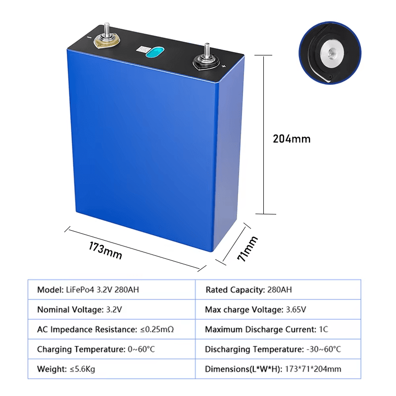
The standard LiFePO4 pack configurations for common inverter voltages are: 4S for 12V nominal, 8S for 24V nominal, and 16S for 48V nominal. For high-voltage systems (96V, 100V), the configuration is 30S to 32S depending on the specific inverter input range. Confirm the exact cell count in your series string before specifying the BMS.
2. Continuous Current Rating
The BMS continuous current rating must comfortably exceed the maximum DC current your inverter will ever demand from the battery. Undersizing this parameter is one of the most common and most damaging BMS specification errors in Nigerian solar installations.
The calculation is straightforward. For a 48V battery system, the maximum DC current draw from the inverter is the inverter’s rated VA output divided by the minimum battery voltage (the voltage at which the inverter cuts off, typically around 44 to 46V for a 48V LiFePO4 system).
For a 5kVA inverter on a 48V system: 5,000VA divided by 46V equals approximately 109A maximum instantaneous DC demand. The BMS must be rated above this. Add a 25% margin for temperature derating, startup surge absorption, and future load growth: 109A times 1.25 equals 136A. A 150A BMS is the correct minimum specification. A 200A BMS provides a comfortable margin.
Using a 100A BMS on a 5kVA system is a common and costly mistake. The BMS will operate its MOSFETs above their thermal rating under full inverter load, degrading progressively until MOSFET failure occurs, typically within 12 to 18 months of regular full-load operation in Nigerian ambient temperatures.
Inverter Size
Battery Voltage
Max DC Current Draw
Minimum BMS Rating (x1.25)
Recommended BMS Rating
1 kVA
48V
~21A
~26A
50A BMS adequate. Most 50A BMS units on the market are suitable.
2 kVA
48V
~42A
~53A
75A or 100A BMS. The 100A is the safer choice with headroom for future load growth.
3 kVA
48V
~63A
~79A
100A BMS minimum. 150A preferred to cover startup surge and derating in hot conditions.
5 kVA
48V
~104A
~130A
150A BMS minimum. 200A strongly recommended for Nigerian conditions and startup surge coverage.
8 kVA
48V
~167A
~209A
200A BMS minimum. Consider a 250A or 300A BMS for robust headroom.
10 kVA
48V
~208A
~260A
250A BMS minimum. 300A preferred. At this scale, evaluate parallel BMS configurations.
5 kVA
96V (2x48V series)
~52A
~65A
100A BMS adequate. High-voltage systems reduce current demand per string significantly.
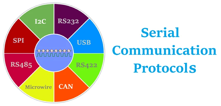
3. Communication Protocol
The BMS must support the specific communication protocol that your inverter expects. This is a binary compatibility requirement: either the protocols match and communication is established, or they do not and the inverter operates blind regardless of how everything else is connected.
Victron MultiPlus, Quattro, EasySolar: CAN bus at 500 kbps (VE.Can). RJ45 connector. Must select battery brand in Victron GX device settings.
Deye SUN-xK-SG hybrid series: RS485 Modbus with Deye protocol variant. Terminal block connection. Select battery brand in Deye system settings menu.
Growatt SPF, SPH, MIN series: RS485 Modbus with Growatt protocol variant. Confirm compatibility with the specific Growatt model before purchasing.
Solis hybrid inverters: RS485 Modbus (Solis variant). Very similar to Deye configuration.
Pylontech batteries: RS485 using proprietary PYLON protocol. Supported natively by most major inverter brands.
If you are using an inverter not on this list, consult the inverter manual for its supported BMS communication protocol and connector type before specifying any BMS. A BMS with the wrong protocol is functionally equivalent to a standard BMS for inverter communication purposes, regardless of its other features.
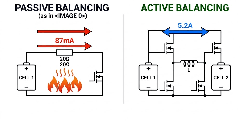
For any LiFePO4 pack above 100Ah cycling daily in a solar storage application, active balancing is a non-negotiable requirement, not an upgrade. The specific reason comes down to mathematics.
A 200Ah pack developing a 5% SOC imbalance between its strongest and weakest cell has a 10Ah energy deficit to correct. A passive BMS with 100mA balancing current needs 100 hours to correct this. A daily cycling pack accumulates new imbalance every cycle. Passive balancing cannot keep up. The pack drifts progressively further out of balance over months, and capacity loss compounds silently.
An active BMS with 2A balancing current corrects the same 10Ah imbalance in 5 hours. The imbalance is resolved within a single overnight charge cycle before the next day’s cycling adds more. Cell matching is maintained over years.
The following table is your BMS purchasing specification sheet. Use it before engaging any supplier. Every parameter in this table must be confirmed from the product datasheet, not from marketing material or verbal claims.
BMS Parameter
Requirement
Notes for Nigerian Solar Installations
Cell count (S rating)
Must match series string exactly
Non-negotiable. 16S BMS for 16S pack. No exceptions.
Continuous current rating
Inverter max DC input current x 1.25 minimum
For 5kVA/48V: ~130A minimum. For 3kVA/48V: ~80A minimum. For 10kVA/48V: ~260A minimum.
Peak/surge current rating
Must cover inverter startup surge
Inverter startup surge can reach 2-3x continuous current for <500ms. Confirm BMS peak rating or add pre-charge circuit.
Communication protocol
Must match inverter’s supported protocol
Victron: CAN (VE.Can). Deye/Growatt/Solis: RS485 Modbus. Pylontech: RS485 PYLON protocol.
Balancing type
Active balancing required above 100Ah daily cycling
Passive balancing only acceptable for small packs under 100Ah with infrequent cycling.
Balancing current
Minimum 1A for 100-200Ah; 2A for 200Ah+
JK BMS active balancer: up to 2A configurable. Verify before purchase, not from marketing material.
Temperature sensors
Minimum 2 thermistors; 3-4 preferred
One on cell stack, one on MOSFET board. Third and fourth sensors improve thermal mapping of large packs.
Charge OTP threshold
Hard cutoff at 50-55 degC for Nigerian conditions
Standard global BMS settings may have cutoff at 60-65 degC, which is too high for Nigerian enclosure temperatures.
OVP threshold
Configurable, not fixed
Must be settable to 3.65V per cell for LiFePO4. Fixed threshold units cannot be optimised for different cell batches.
UVP threshold
Configurable, not fixed
Recommended 2.80V for daily cycling LiFePO4. Fixed units often default to 2.50V which is too close to damage threshold.
Fault history log
Timestamped, minimum 20 events
Essential for post-fault diagnosis. Non-negotiable for professional installations.
Bluetooth app
Required for smart BMS
App must display per-cell voltages, temperatures, current, SOC, balance status, and fault log.
Short circuit response time
Under 200 microseconds
Verify in datasheet. Budget units often use firmware detection (slower). Hardware comparator detection is preferred.
Port configuration
Separate-port preferred for solar applications
Allows solar charging even when discharge path is in protection state. Common-port acceptable for simpler setups.
PURCHASING RULE
Never confirm a BMS specification from the product label or a vendor’s verbal description. Request the technical datasheet. Verify continuous current rating, short circuit response time, temperature sensor count, and communication protocol from the datasheet. Budget BMS units frequently overstate current ratings on their labels. A BMS labelled 200A that has MOSFETs rated for 100A continuous will fail at the 100A level, not the 200A label.
Why Most Installations Are Undersized
Current rating is the BMS specification most frequently under-specified in Nigerian solar installations, and the one most directly responsible for premature BMS hardware failure.
The standard explanation is cost: a higher current BMS costs more, so installers select the lower-rated unit to reduce the bill of materials. The problem is that this cost saving is entirely false economy. A BMS MOSFET running continuously above its rated current operates in a condition called second breakdown risk. The junction temperature rises above the thermal threshold at which the MOSFET’s current handling becomes non-uniform. Hot spots form in the MOSFET die. The device degrades from the inside, and MOSFET resistance increases with each thermal stress cycle.
The failure mode is slow and invisible. There are no fault codes. The BMS appears to function normally. But every month the MOSFETs degrade slightly more. After 12 to 18 months, one MOSFET fails in a partially-conducting state: it no longer switches fully off when the BMS commands it. Protection is compromised. Overcurrent and short circuit protection may no longer respond correctly.
The Derating Principle for Nigerian Conditions
BMS current ratings are specified at 25 degC ambient temperature. In Nigerian installations where MOSFET temperatures can reach 50 to 70 degC during operation, the effective current capacity of the MOSFET is reduced. This derating is typically 20 to 40% depending on the MOSFET technology and PCB thermal design.
A BMS rated at 150A at 25 degC may have an effective capacity of 90 to 120A at 55 degC junction temperature. This is why the 25% margin rule in the specification table is a minimum, not a maximum. In Nigerian conditions, a 35 to 40% margin is defensible for installations where the BMS enclosure temperature regularly exceeds 45 degC.
The practical rule: if your inverter demands 100A maximum, select a BMS rated for 150A absolute minimum, and prefer 200A for any installation in a non-air-conditioned environment.
Startup Surge: The Hidden Current Demand
Inverters contain large DC bus capacitors that charge from zero to full pack voltage when the inverter is first energised. This capacitor charging creates a momentary current spike that can reach 3 to 5 times the inverter’s normal operating current for 10 to 100 milliseconds.
For a 5kVA inverter that normally draws 100A, the startup surge can briefly reach 300 to 500A. A BMS rated at 150A continuous will see this surge and may trip its OCP protection every time the inverter starts. The installer assumes the BMS is faulty. It is not.
Solutions in order of preference: add a pre-charge circuit that slowly charges the inverter capacitors through a resistor before the main BMS circuit connects; specify a BMS with a configurable peak current threshold separate from its continuous OCP threshold; or install a manual pre-charge procedure where the inverter is connected via a current-limiting resistor before full battery connection.
DC cable sizing is directly linked to BMS current rating and must be specified to handle the maximum BMS-allowed current. Our guide on DC cable sizing for off-grid solar systems covers the cable selection calculation in full.
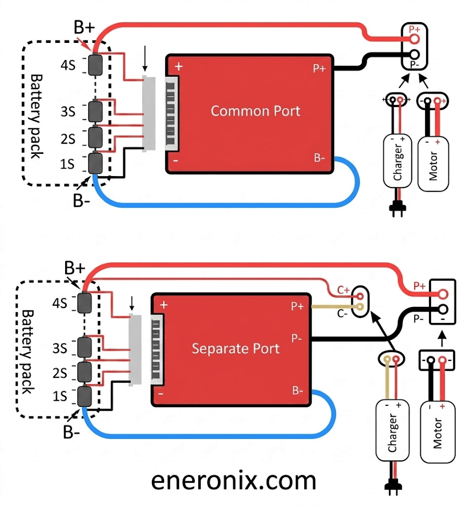
Common-Port vs Separate-Port BMS: Which Configuration to Choose
The port configuration of a BMS determines how charge and discharge current paths are controlled. This choice has practical implications for how the system behaves during fault conditions and whether solar charging can continue during low-voltage protection events.
Parameter
Common-Port BMS
Separate-Port BMS
Terminal configuration
Single B+ and B- pair serves both charge and discharge
Separate C+ for charge input; P+ for discharge output; shared negative
MOSFET configuration
One set of MOSFETs handles both current directions
Dedicated charge FETs and dedicated discharge FETs, independently controlled
Independent path control
No. Cannot allow charge while blocking discharge or vice versa
Yes. BMS can allow solar charging while discharge path is in protection (UVP state)
Wiring complexity
Simple. One positive and one negative terminal to/from battery bus
More complex. Separate charge and discharge positive terminals require correct wiring
Short circuit behaviour
Both charge and discharge blocked on any fault
Fault on charge FET does not necessarily block discharge; allows continued load service
Cost
Lower (fewer MOSFETs and gate drivers)
Higher (more MOSFETs, two independent gate driver circuits)
Best for
Simple off-grid systems; systems without simultaneous charge and discharge requirements
Solar systems where you want charging to continue during load discharge; any hybrid inverter system
Nigerian market recommendation
Acceptable for small simple systems under 100Ah
Preferred for all systems above 100Ah and any hybrid inverter application
The Solar Charging Scenario That Makes Separate-Port Essential
Consider a 48V solar system where the battery has been heavily discharged overnight and the weakest cell hits UVP at 2.80V at 06:00. With a common-port BMS, the BMS opens both charge and discharge MOSFETs simultaneously. The battery is disconnected from everything, including the solar array that is just starting to produce power as the sun rises.
With a separate-port BMS, the BMS opens only the discharge MOSFET to protect the weak cell. The charge MOSFET remains closed. Solar charging continues and begins restoring the pack. By 07:30, the weak cell has recovered above the UVP reset threshold and full operation resumes. The system self-recovers without any manual intervention.
This scenario happens regularly in daily-cycling off-grid solar systems with any degree of cell imbalance. The separate-port BMS handles it gracefully. The common-port BMS forces a manual reset or waits for the BMS’s auto-reset timer. In a remote installation with no operator present during the morning hours, this difference is significant.
Temperature Protection: The Most Critical Parameter for Nigerian Conditions
Temperature protection is the BMS parameter most frequently under-specified for the Nigerian climate, and the one that has the largest long-term impact on battery lifespan in West African field conditions.
Standard BMS units designed for global markets often have charge OTP hard cutoffs set at 55 to 65 degC. This is reasonable for installations in temperate climates where battery enclosure temperatures rarely exceed 35 degC. It is inadequate for Nigerian installations where unventilated enclosures routinely reach 45 to 55 degC during the dry season.
At 50 degC cell temperature, electrolyte decomposition in LiFePO4 cells is proceeding at roughly twice the rate it does at 40 degC. At 55 degC, it is proceeding at approximately four times the rate. A battery running chronically at 50 to 55 degC without thermal cutoff is experiencing continuous accelerated aging on every charge cycle.
The correct approach for Nigerian installations is to set the charge OTP soft limit at 40 to 42 degC (begin reducing CCL at this point) and the hard cutoff at 50 degC. This is more conservative than global defaults but correctly matches the thermal reality of Nigerian field conditions.
FIELD REALITY
In Nigerian solar installations where battery lifespan has been significantly shorter than expected, elevated enclosure temperature during charging is the single most frequently identified contributing factor. The BMS temperature protection is the only automated safeguard against this. A BMS with temperature protection disabled or configured to global defaults rather than Nigerian-specific thresholds is providing incomplete protection in this environment.
BMS Tiers: What You Get at Each Price Point
The BMS market in Nigeria spans three broad tiers of capability. Understanding what each tier provides and what it lacks prevents both over-specification (paying for features you do not need) and under-specification (saving money on a unit that cannot protect your investment properly).
Feature
Budget / Standard BMS
Mid-Tier Smart BMS
Full-Feature Smart BMS (e.g., JK BMS)
Protection functions
OVP, UVP, OCP, SCP only. No temp protection on some units.
All protection functions including configurable OTP
All protection functions, fully configurable
Balancing
Passive only, 30-100mA
Passive or basic active (500mA-1A)
Active balancing 1-5A, configurable threshold
Communication
None
RS485 on some variants; no CAN
Full RS485 + CAN options; Bluetooth app
SOC reporting to inverter
None. Inverter uses voltage estimation.
Basic RS485 SOC broadcast on some units
Full CVL/CCL/DCL + SOC + cell data broadcast
Fault history log
None
Basic (last fault only on some units)
Full timestamped log, 50+ events
Threshold configurability
Fixed
Limited (chemistry profiles only)
Fully configurable per parameter
Temperature sensors
0-1 (some budget units have none)
1-2
2-4 with configurable placement
Typical cost (16S, 100A)
3,000 to 8,000 NGN
8,000 to 18,000 NGN
18,000 to 45,000 NGN
Suitable for
Very small packs, test benches, cost-constrained temporary builds
Small home systems, infrequent cycling, modest capacity
Any daily-cycling solar storage system above 100Ah
Nigerian solar recommendation
Not recommended for any professional installation
Acceptable for 12V or 24V systems under 100Ah
Minimum specification for 48V systems in daily use
The budget BMS tier is not suitable for any professional installation or any system where the battery represents a meaningful investment. The cost saving of 10,000 to 20,000 NGN on the BMS is typically recovered and exceeded by the battery capacity loss that results from inadequate protection and balancing within the first 12 to 18 months of operation.
The mid-tier smart BMS is acceptable for small 12V or 24V systems with moderate cycling frequency. For any 48V daily-cycling solar installation, the full-feature smart BMS is the correct specification. The additional cost, typically 15,000 to 25,000 NGN above the mid-tier option, is justified by the communication capability alone, as covered in our Phase 1 article on smart versus standard BMS.
Which BMS for Which System
The following table maps common Nigerian solar installation scenarios to specific BMS specifications and practical product recommendations. Use it as a starting point for your specification process, then verify against the complete checklist table.
Installation Scenario
BMS Specification Required
Practical Recommendation
48V 100Ah, Deye hybrid inverter, daily cycling, Nigerian home
16S, 150A, RS485 Modbus, active balancing 1A+, separate-port, Bluetooth app, configurable thresholds
JK BMS B2A8S20P (100A active) or equivalent 150A variant. Configure RS485 for Deye protocol.
16S, 200A+, CAN bus (VE.Can), active balancing 2A+, Bluetooth app
JK BMS CAN variant, or consider sealed Pylontech/BYD units with native Victron integration.
48V 100Ah, no inverter communication required, backup UPS application
16S, 150A, passive or basic active balancing, Bluetooth app minimum
JK BMS 100A passive or basic active. Communication not required but Bluetooth monitoring still valuable.
DIY 24V (8S) 200Ah, small off-grid cabin, Growatt SPF inverter
8S, 150A, RS485, active balancing 1A+
JK BMS 8S active balancer variant. Verify 8S compatibility before ordering.
Sealed commercial pack (Pylontech US3000C)
Already integrated. No external BMS required.
Connect RS485 cable to inverter. Configure inverter to Pylontech/PYLON protocol. Verify communication in inverter display.
For guidance on how the BMS selection integrates with the full battery bank sizing process, our 48V lithium battery sizing guide covers the complete calculation from load audit to battery bank design to BMS specification.
What to Verify Before Purchasing:
The Nigerian solar equipment market contains a significant proportion of counterfeit and mislabelled BMS units, particularly in the budget and mid-tier segments. Protecting yourself from a fraudulent purchase requires verifying specific parameters before committing.
Request the Technical Datasheet
A genuine product from a reputable manufacturer has a published technical datasheet with specific values for continuous current rating, peak current rating, operating temperature range, short circuit response time, communication protocol, cell count compatibility, balancing current, and MOSFET specification. If a supplier cannot provide a datasheet, the product’s claimed specifications cannot be verified.
Verify the MOSFET Specification
Open the datasheet and find the MOSFET component number. Cross-reference it against the manufacturer’s published datasheet for that MOSFET. Confirm the MOSFET’s actual continuous current rating at the expected junction temperature. A BMS claiming 200A continuous using MOSFETs rated at 60A continuous each (and therefore requiring at least 4 in parallel to achieve 200A) should be verified to confirm the parallel MOSFET count on the PCB.
Test the Bluetooth App Before Installation
Pair the BMS Bluetooth app with the unit before wiring it into the battery pack. Confirm that individual cell voltages appear, that the app is responsive, and that configuration parameters are accessible. A unit with a non-functional app cannot be diagnosed in the field. Discovering this after full installation is significantly more expensive than discovering it during pre-installation testing.
Confirm Protocol with Your Inverter
Before purchasing, identify the exact inverter model and firmware version and confirm that the BMS protocol is supported. For Deye and Growatt systems specifically, the supported BMS brand list varies between firmware versions. A BMS that worked with Deye firmware version 1.4x may not work with firmware version 1.6x due to register map changes. Verify with the inverter supplier that the BMS model you are purchasing is on the current supported list for your inverter model and firmware version.
What Most Installers Get Wrong When Choosing a BMS
MISTAKE 1
Choosing the BMS after specifying the battery cells, rather than as part of the initial system design. BMS selection must be done alongside inverter selection, cable sizing, and battery capacity calculation. The BMS current rating depends on the inverter. The communication protocol depends on the inverter. The cell count depends on the pack voltage. These are concurrent decisions, not sequential ones.
MISTAKE 2
Selecting the cheapest BMS that matches the cell count and trusting the current rating label. Budget BMS labels routinely overstate current ratings. A BMS labelled 200A with undersized MOSFETs is effectively a 100A or 120A BMS that will fail at full load. Verify from the datasheet, not the label.
MISTAKE 3
Ignoring the inverter communication protocol and then troubleshooting for weeks after installation when SOC reporting is wrong. Protocol compatibility is a pre-purchase verification step, not a commissioning step. Confirm protocol match before ordering. Do not assume that because a BMS has an RS485 port it will work with your inverter. The specific protocol variant must match.
MISTAKE 4
Using a 16S passive BMS for a 200Ah 48V daily-cycling system to save cost. This is the most common specification error in the Nigerian residential solar market. The passive BMS will protect the cells from hard faults but will allow cell imbalance to compound over 12 to 18 months, reducing pack capacity by 20 to 40% before the customer realises there is a problem. Active balancing is not optional at this system scale.
For a complete analysis of how specification errors compound into battery system failures over time, our article on why most solar battery systems fail before year 2 is essential reading before any new installation.
Commissioning the BMS Correctly
Selecting the right BMS is necessary but not sufficient. The BMS must also be commissioned correctly to deliver the protection it is capable of providing. The most common commissioning failures are: connecting power cables but not the communication cable, not configuring the inverter battery protocol setting, using default OVP and UVP thresholds rather than configuring them for the specific cells installed, and not performing an initial top balance before the first service cycle.
A BMS installed but not configured is functionally equivalent to a lower-tier BMS for most of its advanced capabilities. The communication is not transmitting. The thresholds are not optimised for the cells. The balancing has not been given an opportunity to equalise the cells before cycling begins. These configuration steps are not optional extras. They are the difference between a BMS that performs its specified function and one that sits in the system doing less than it is capable of.
The complete 10-stage commissioning protocol for hybrid solar systems including BMS configuration verification is in our hybrid solar system commissioning checklist. Stage 5 specifically covers BMS communication verification and threshold configuration.
Frequently Asked Questions
How do I choose the right BMS for my LiFePO4 battery?
Start with four non-negotiable parameters: cell count (must match your series string exactly), continuous current rating (must exceed your inverter’s maximum DC input current by at least 25%), communication protocol (must match your inverter’s supported protocol: CAN for Victron, RS485 for Deye/Growatt/Solis), and balancing type (active balancing required for packs above 100Ah in daily cycling service). Everything else is secondary to getting these four correct.
What current rating BMS do I need for a 5kVA inverter?
A 5kVA inverter on a 48V system can draw up to approximately 104A DC at full load. You need a BMS rated for at least 130A continuous (25% margin above maximum demand). A 100A BMS is undersized for this application and will either trip repeatedly under full load or run its MOSFETs in a thermal stress zone that shortens its life. Use a 150A or 200A BMS for a 5kVA system to have adequate headroom.
Can I use a 16S BMS on a 15S LiFePO4 pack?
No. Never use a BMS with more cell count than your actual pack configuration. A 16S BMS on a 15S pack leaves one cell monitoring channel unconnected. The BMS may read that channel as zero volts and interpret it as a severely discharged cell, triggering immediate UVP protection. Always match the BMS cell count exactly to your series string configuration.
What is the difference between common-port and separate-port BMS?
A common-port BMS uses the same terminals for both charging and discharging. Charge and discharge current flow through the same port. A separate-port BMS has dedicated charge input terminals and dedicated discharge output terminals. Separate-port allows the BMS to permit solar charging while blocking load discharge (or vice versa) independently. It is the preferred configuration for solar systems where you want to continue accepting solar charge even when the pack is in a low-voltage protection state.
Does my BMS need to support CAN bus or RS485?
It depends on your inverter. Victron inverters require CAN bus (VE.Can). Most Chinese hybrid inverters including Deye, Growatt, and Solis use RS485 Modbus. Pylontech batteries use a proprietary RS485 protocol. Check your inverter manual for the supported BMS communication protocol before purchasing. A BMS with the wrong protocol cannot communicate with your inverter regardless of how it is wired.
Is the JK BMS good for a 48V LiFePO4 solar system?
Yes. The JK BMS active balancer series is one of the most capable and widely deployed BMS options for 48V LiFePO4 DIY packs in the Nigerian and West African market. It combines active balancing up to 2A, full RS485 communication compatible with Deye, Growatt, and Solis, Bluetooth app monitoring, configurable protection thresholds, and current ratings up to 200A at a price point that represents strong value for its feature set.
What happens if my BMS current rating is too low?
An undersized BMS will either trip its OCP protection repeatedly under normal peak loads, or it will operate with its MOSFETs running above their safe current rating, causing progressive thermal degradation of the switching components. MOSFET failure from sustained overcurrent is one of the most common BMS hardware failure modes in Nigerian solar installations. Always specify a BMS with at least 25% current headroom above your maximum expected load.
Can I use one BMS for multiple batteries in parallel?
A single BMS manages one series battery pack. If you connect two battery packs in parallel, each pack needs its own BMS. The two BMS units operate independently, each protecting its own cells. For multi-pack systems where you want a single SOC reading reported to the inverter, one BMS acts as the master and reports aggregate data while the others operate as independent protection systems. This architecture is covered in detail in the Eneronix series on multi-battery parallel systems.
What BMS features are essential for a Nigerian solar installation?
The non-negotiable features for Nigerian conditions are: per-cell voltage monitoring with configurable OVP and UVP thresholds, temperature monitoring with at least two thermistors and a hard charge cutoff at 50 to 55 degrees C (critical for hot enclosure conditions), active balancing with at least 1A current for packs above 100Ah, RS485 or CAN communication matching the inverter, and a Bluetooth app with a fault history log. The temperature protection and active balancing are specifically important for Nigerian ambient temperature conditions.
How do I know if a BMS is genuine or counterfeit?
Purchase from established distributors with product warranties, not from anonymous market stalls or social media sellers without verifiable business addresses. Genuine JK BMS units have a QR code that links to the manufacturer verification portal. Request the BMS datasheet and verify that the specifications match what is advertised. Counterfeit BMS units typically have lower actual current ratings than claimed, no genuine app connectivity, and fixed protection thresholds that cannot be configured.
I am Engr. Ubokobong Ekpenyong, a solar specialist and lithium battery systems engineer with over five years of hands-on experience designing, assembling, and commissioning off-grid solar and energy storage systems. My work focuses on lithium battery pack architecture, BMS configuration, and system reliability in off-grid and high-demand environments.
Contains information related to marketing campaigns of the user. These are shared with Google AdWords / Google Ads when the Google Ads and Google Analytics accounts are linked together.
90 days
__utma
ID used to identify users and sessions
2 years after last activity
__utmt
Used to monitor number of Google Analytics server requests
10 minutes
__utmb
Used to distinguish new sessions and visits. This cookie is set when the GA.js javascript library is loaded and there is no existing __utmb cookie. The cookie is updated every time data is sent to the Google Analytics server.
30 minutes after last activity
__utmc
Used only with old Urchin versions of Google Analytics and not with GA.js. Was used to distinguish between new sessions and visits at the end of a session.
End of session (browser)
__utmz
Contains information about the traffic source or campaign that directed user to the website. The cookie is set when the GA.js javascript is loaded and updated when data is sent to the Google Anaytics server
6 months after last activity
__utmv
Contains custom information set by the web developer via the _setCustomVar method in Google Analytics. This cookie is updated every time new data is sent to the Google Analytics server.
2 years after last activity
__utmx
Used to determine whether a user is included in an A / B or Multivariate test.
18 months
_ga
ID used to identify users
2 years
_gali
Used by Google Analytics to determine which links on a page are being clicked
30 seconds
_ga_
ID used to identify users
2 years
_gid
ID used to identify users for 24 hours after last activity
24 hours
_gat
Used to monitor number of Google Analytics server requests when using Google Tag Manager
1 minute
You can find more information in our Cookie Policy and .

: Prices, Types & How to Choose")

: Prices, Types & How to Choose")


")


")
