Learn how to build a LiFePO4 battery pack step-by-step, including cell testing, top balancing, BMS wiring, cable sizing, fuse protection, and inverter commissioning for reliable solar storage in Nigeria.
Building your own LiFePO4 battery pack is one of the most cost-effective ways to get high-quality solar storage in Nigeria. A well-built DIY pack from Grade A cells with a proper BMS will outperform many commercial units at a fraction of the price.
But the difference between a well-built pack and a badly built one is not obvious from the outside. Both use the same cells. Both have a BMS installed. Both connect to the same inverter. The difference shows up 18 months later, when the badly built pack is delivering 60% of its original capacity and nobody can explain why.
This guide covers the entire build process for a 48V 200Ah LiFePO4 pack, from cell selection through to inverter commissioning. Every calculation is shown in full. Every step has an engineering rationale. The common mistakes section at the end documents the six errors that I have personally seen destroy otherwise good packs.
Do not skip steps. Do not take shortcuts on calculations. A battery pack stores enough energy to cause a serious fire if something goes wrong. Build it correctly.
TL;DR
What this covers: complete step-by-step guide to building a 48V 200Ah LiFePO4 battery pack, with every calculation worked out in full. Who it is for: DIY builders, solar engineers, and installers assembling custom LiFePO4 packs for off-grid and hybrid solar systems. Key takeaways: – Cell selection, capacity testing, and top balancing before assembly are not optional steps. – Every component: cells, BMS, busbars, fuse, cables must be calculated, not guessed. – The pack is not ready to use until the BMS is configured and communication with the inverter is verified. – The three most common build mistakes are: skipping capacity testing, undersized cables, and missing the pre-charge circuit. Estimated read time: 18 to 22 minutes.
Step 0: Define the Build Specification
Before ordering a single component, define the complete specification. Every component decision flows from this table. Changes to any parameter after ordering components may require reordering.
Parameter
Value / Decision
Target pack voltage
48V nominal (51.2V nominal, LiFePO4)
Target capacity
200Ah
Target energy
200Ah x 51.2V = 10.24 kWh gross; ~8.2 kWh usable at 80% DoD
Cell configuration
16S1P (16 cells in series, 1 parallel string)
Cell chemistry
LiFePO4 (Lithium Iron Phosphate)
Cell format
Prismatic (Grade A, 200Ah rated)
Target inverter
5kVA Deye hybrid, 48V nominal input
Maximum inverter DC current
5,000 VA / 46V = 108.7A
BMS specification
16S, 200A, RS485, active balancing 2A, JK BMS
Target cycle life
3,000+ cycles at 80% DoD
Intended location
Indoor generator room, non-air-conditioned, Lagos
With this specification confirmed, we know: we need 16 prismatic LiFePO4 cells at 200Ah each, a 16S 200A BMS with RS485, copper busbars sized for 150A, 50mm2 power cables, a 300A ANL fuse, and a pre-charge circuit. All of these are calculated below.
Step 1: Cell Selection and Procurement
Cell quality is the foundation of the entire pack. A BMS cannot recover capacity from bad cells. An active balancer cannot correct for a cell with 15% lower capacity than its neighbours. Get the cells right first.
Cell Parameter
Requirement
Engineering Rationale
Rated capacity
200Ah minimum
Our target pack is 200Ah. Using 200Ah cells means 1P configuration. Using 100Ah cells would require 2P (parallel), adding complexity.
Chemistry
LiFePO4 only
NMC is not acceptable for this application. LiFePO4 thermal stability is essential in a non-air-conditioned Lagos generator room.
Cell format
Prismatic preferred
Prismatic cells are easier to busbar, easier to compress, and have better thermal contact than cylindrical for this capacity range.
Nominal voltage
3.2V per cell
16 cells x 3.2V = 51.2V nominal. Confirms 16S is the correct configuration for 48V.
Rated charge voltage
3.65V maximum
16 x 3.65V = 58.4V. Must be within the inverter’s charge voltage range. Deye 5kVA accepts up to 60V. Confirmed compatible.
Rated discharge cutoff
2.5V minimum (datasheet)
We will configure BMS UVP at 2.80V, more conservative than the absolute minimum. This protects cycle life.
C-rate (discharge)
Minimum 1C continuous
System maximum: 108.7A / 200Ah = 0.54C. Well within 1C. Any Grade A 200Ah LiFePO4 cell handles this comfortably.
Grade
Grade A only
Grade B cells have a higher proportion of production defects and wider capacity variation. For a pack that will cycle 3,000+ times, Grade A is the only acceptable specification.
Batch matching
Same production batch, capacity tested
Cells from different batches have different internal resistance profiles even at the same rated capacity. Same-batch cells diverge more slowly.
Internal resistance
Under 0.25 milliohms (Grade A 200Ah typical)
High internal resistance cells heat more under load and age faster. Request IR measurements from the supplier with the cells.
SOURCING NOTE
In the Nigerian market, Grade A prismatic LiFePO4 cells at 200Ah are available through solar equipment importers and direct Alibaba sourcing. When sourcing directly, always request a quality inspection report (QC report) showing individual cell test data for the specific batch. A reputable supplier should be able to provide: rated capacity, actual measured capacity at 0.2C, internal resistance at 25 degC, and open circuit voltage. If a supplier cannot provide this data, source elsewhere.
Step 2: Individual Cell Capacity Testing
Every single cell must be tested individually before assembly. I cannot overstate how important this step is. You are about to commit these 16 cells to a pack that you will not disassemble for potentially years. If one of them has a capacity defect that you did not catch here, you will be chasing a mysterious capacity loss and imbalance problem for the life of the pack.
The test takes time. At 0.2C (40A) discharge rate for a 200Ah cell, a full discharge takes 5 hours. With a simultaneous charge cycle, expect 8 to 10 hours per cell. If you have 4 capacity testers, you can run 4 cells simultaneously and complete all 16 cells in 2 days.
Capacity Test Step
Engineering Notes
Charge each cell to 3.65V using a single-cell charger at 0.2C (40A for 200Ah cell). Hold at 3.65V until charge current drops below 2A (0.01C).
This is a full charge. Do not skip the CV hold. A cell terminated at the bulk charge voltage without CV hold is not fully charged.
Rest the cell for 30 minutes at open circuit.
Allows voltage to relax to the true open-circuit value. Immediately after charging, cell voltage is inflated by the charge current’s internal resistance effect.
Discharge the cell at 0.2C (40A) through a load down to 2.50V. Measure total Ah discharged using an accurate coulomb counter.
0.2C is the standard capacity test rate. Higher rates give lower apparent capacity due to internal resistance effects. Use 0.2C for all 16 cells to ensure consistent comparison.
Record: cell ID, measured capacity (Ah), open-circuit voltage after 30-minute rest post-discharge, and measured internal resistance.
This data determines which cells to use and how to pair them in the string.
Accept cells within 2% of rated capacity. For 200Ah cells: accept 196Ah to 204Ah. Discard or return cells outside this range.
A 5% capacity outlier in a 16S string will diverge significantly from the rest of the pack within 200 cycles. A 2% tolerance keeps the string matched for much longer.
Rank all accepted cells by measured capacity. For a 16S1P pack, sort the 16 cells so that no two adjacent cells in the string have a capacity difference greater than 1Ah.
Placing matched cells next to each other in the string minimises the voltage gradient that drives imbalance accumulation.
WHAT TO DO WITH REJECTS
A cell that tests below 196Ah (2% of 200Ah) should be returned to the supplier if within the return window, or set aside for a smaller pack where its actual capacity is the designed capacity. Do not include it in a 200Ah pack. A 190Ah cell in a 200Ah string diverges by 5% from day one and creates a persistent imbalance that the BMS will be fighting for the life of the pack.
KEY TAKEAWAY
Capacity testing takes 2 days. Skipping it costs you 18 months of mystery diagnostics. Test every cell.
Step 3: Top Balancing All Cells Before Series Assembly
After the capacity test, all 16 cells are at approximately 2.50V (the discharge cutoff voltage). They need to be individually charged and then balanced to the same state of charge before being connected in series.
Top balancing in parallel is the cleanest method. All cells connected positive-to-positive and negative-to-negative form a parallel bank that self-equalises to a common voltage. A power supply then charges this parallel bank to 3.65V.
Top Balance Step
Engineering Rationale
Connect all 16 cells in parallel (positive to positive, negative to negative) using temporary jumper cables or a dedicated balance board. Do NOT connect them in series for this step.
Parallel connection forces all cells to the same voltage. Current flows between cells to equalise their state of charge. This is safe at this stage because the voltage difference between cells is small (all should be within 0.1V after capacity testing).
Connect a power supply set to 3.65V and current limited to 5 to 10A to the parallel cell bank. Charge until the current drops below 0.5A.
The parallel bank charges to 3.65V at a gentle rate. When current drops to near zero, all 16 cells are at 3.65V simultaneously. This is true top balance.
Disconnect the power supply. Measure each cell voltage individually. All 16 should read between 3.62V and 3.65V. Any cell reading below 3.60V has not accepted the charge and should be investigated.
A cell that will not charge to 3.65V even in a parallel bank may have a high-resistance internal connection or an early-stage defect. Do not include it in the final pack.
Disconnect the parallel connections. Immediately proceed to series assembly. Do not leave cells in the top-balanced state for more than a few hours before assembly, as self-discharge will begin to diverge them.
The goal of top balancing is to start the first series cycling with all cells at the same state of charge. Delaying assembly wastes the work.
SAFETY DURING PARALLEL TOP BALANCE
When connecting cells in parallel for top balance, connect all negative terminals first, then all positive terminals. If two cells are at significantly different voltages (more than 0.3V apart), a large equalisation current will flow when they are connected in parallel. Limit this by using a 1-ohm resistor in series with each cell’s positive connection during the first few minutes of parallel connection, then shorting the resistors out once the voltages have equalized. In practice, after capacity testing, cells are all near 2.50V and this risk is low.
KEY TAKEAWAY
Top balance takes 4 to 6 hours but means the pack starts its first service cycle with zero imbalance. Every cycle from that point is the active balancer’s job to maintain, not correct.
Step 4: Series Assembly Connecting 16 Cells in Series
Series assembly means connecting the positive terminal of Cell 1 to the negative terminal of Cell 2, the positive terminal of Cell 2 to the negative terminal of Cell 3, and so on through to Cell 16. The most negative point in the string (Cell 1 negative) becomes the pack B- terminal. The most positive point (Cell 16 positive) becomes the pack B+ terminal.
Cell Arrangement and Pack Voltage Verification
Before making any connections, lay out all 16 cells and number them 1 through 16 based on your capacity test ranking (most similar capacities adjacent in the string). Measure the voltage of each cell with a multimeter: all should be between 3.62V and 3.65V from the top balance.
Calculate the expected series pack voltage: sum of all 16 cell voltages. If all cells are at 3.64V, expected pack voltage = 16 x 3.64V = 58.24V. Measure across the outermost terminals after series connection and verify it matches the sum within 0.1V.
Busbar Sizing Calculation
The busbars connect the cells in series and carry the full pack current. They must be sized for the maximum current demand plus margin.
Busbar Parameter
Value / Calculation
Engineering Rationale
Maximum continuous current
108.7A (from inverter sizing) plus 25% margin = 135A. Round to 150A for busbar design.
Busbars carry the same current as the BMS. Size them to the BMS current rating, not just the calculated maximum.
Busbar material
Copper (preferred) or nickel-plated copper
Copper has the lowest resistivity of common busbar materials (1.72 micro-ohm-cm). Nickel plating prevents oxidation at cell terminal contact points. Aluminium is acceptable in some applications but not recommended for this build.
Busbar cross-sectional area
Calculation: A = (I x rho x L) / V_drop_max. For 150A, copper, 50mm length: A = (150 x 1.72e-8 x 0.05) / 0.001 = 129 mm2. Use 150mm2 copper busbar for margin.
Where A = cross-sectional area (m2), I = current (A), rho = copper resistivity (1.72e-8 ohm-m), L = busbar length (m), V_drop_max = acceptable voltage drop per busbar (0.001V is conservative).
Busbar thickness and width
For 150mm2: 3mm thick x 50mm wide = 150mm2. Standard available size.
Flat bar format is standard for prismatic cell busbars. 3mm copper is stiff enough to maintain good contact pressure without bending.
Contact torque
4 to 6 Nm for M6 bolts on cell terminals
Under-torqued connections have high contact resistance. Over-torqued connections damage cell terminal threads. Use a torque wrench. This is not optional.
Contact surface preparation
Clean terminal surfaces with isopropyl alcohol before assembly. Apply a thin layer of electrical contact grease to prevent oxidation.
Oxidised copper surfaces have 10 to 50 times higher contact resistance than clean surfaces. Contact resistance creates heat at the joint, which accelerates corrosion.
Series Connection Procedure
Mount all 16 cells in the enclosure in their planned positions. Confirm the physical layout allows busbars to reach between adjacent cell terminals without bending stress.
Clean all cell terminal surfaces with isopropyl alcohol on a clean cloth. Apply a thin layer of electrical contact grease (NoOx-ID or equivalent) to each terminal contact surface.
Connect Cell 1 positive to Cell 2 negative using the first busbar. Use the M6 bolts that came with the cells or matching stainless steel M6 bolts. Torque to 4 Nm on the first pass, then 6 Nm on the second pass.
Continue connecting adjacent cells in sequence through to Cell 16.
Measure pack terminal voltage across Cell 1 negative to Cell 16 positive. Verify it matches the expected sum.
Check each busbar connection temperature after 5 minutes with an IR thermometer. All should be within 2 to 3 degC of ambient. A hot busbar connection indicates a poorly torqued or contaminated contact point. Disassemble, clean, and retorque.
DO NOT RUSH THE TORQUE STEP
Undertorqued busbar connections are the leading cause of connection resistance problems in DIY packs. 4 Nm feels like very little on an M6 bolt. Use a proper torque wrench. Do not estimate by feel. A connection that was fine at assembly can loosen from thermal cycling in a hot enclosure. Check all connections at the 30-day inspection.
Step 5: Main Fuse and Protection Circuit
Before the BMS is connected, the main protection fuse must be installed. The fuse sits between the positive cell terminal (Cell 16 positive / pack B+) and the BMS B+ terminal. Its job is to protect the cables and cells from a wiring fault that could draw uncontrolled current from the fully charged cell stack.
Fuse Parameter
Value / Decision
Engineering Rationale
Fuse purpose
The main fuse protects the cable between the battery positive terminal and the BMS. It is the last line of defence against a wiring fault that could allow uncontrolled current to flow from the full energy of the cell stack through a short circuit path.
Without the fuse, a wiring fault or BMS MOSFET short failure could pass thousands of amps through inadequately sized cables, causing a fire.
Fuse location
At the positive terminal of the battery pack, as close to the cells as physically possible. Before the BMS B+ terminal.
The fuse must be in the unfused cable segment. The shorter that segment, the less cable can contribute to a fire if something goes wrong before the fuse.
Fuse rating calculation
Fuse rating = BMS continuous current rating x 1.25 to 1.5. For a 200A BMS: 200A x 1.25 = 250A minimum fuse rating. Use a 300A ANL or Class T fuse. Do not use a 200A fuse: it may nuisance blow under peak demand.
The fuse must be rated above the BMS OCP threshold to allow the BMS to trip first under overload. The fuse is for wiring fault protection, not for load limiting.
Fuse type
ANL (Automotive New Line) fuse or Class T fuse. Not automotive blade fuses or glass fuse. For 48V battery systems: ANL fuses are widely available in Nigeria at 200A, 300A, and 400A ratings.
ANL fuses are designed for DC battery applications. Their interrupt rating (maximum fault current they can safely interrupt) is specified for DC systems. Automotive blade fuses are not rated for this duty.
ANL fuse holder
Waterproof or sealed ANL fuse holder rated for the fuse current. Bolt connection to cable lugs on both entry and exit sides. Torque bolts to the manufacturer’s specification.
A loose ANL fuse holder connection creates resistance that heats the holder during normal operation. Over time, the heating degrades the fuse and holder contacts.
Pre-charge circuit
A pre-charge resistor and relay circuit between the battery P+ terminal and the inverter DC input. Use a 50 to 100 ohm, 10W resistor and a relay that bypasses the resistor after 500ms to 1 second.
When the inverter is first connected, its DC bus capacitors charge through the pre-charge resistor rather than directly from the battery. This limits the inrush current that would otherwise trip the BMS OCP protection at every inverter startup.
KEY TAKEAWAY
The ANL fuse protects your wiring. The BMS protects your cells. You need both. A battery system without a main fuse is relying entirely on the BMS to prevent a wiring fire. One BMS MOSFET short failure later, you have no protection at all.
Step 6: Main Power Cable Sizing and Installation
Power cables carry the full charge and discharge current between the cells, BMS, and inverter. Undersized cables generate heat, cause voltage drop errors in the BMS measurement, and create fire risk.
The cable sizing calculation uses Ohm’s law. For a cable of length L, cross-sectional area A, carrying current I, the voltage drop is:
V_drop = I x (rho x L / A)
Where rho for copper = 1.72 x 10⁻⁸ ohm-metres, L is the cable length in metres, and A is the cross-sectional area in square metres.
Target: keep total voltage drop across all power cables below 0.5V under maximum load. This ensures the BMS and inverter are measuring voltages close to the actual cell terminal voltages.
Cable Segment
Sizing Calculation
Engineering Notes
Battery to BMS (B+ and B-)
Maximum current: 150A (BMS rated current). Cable type: flexible welding cable or marine-grade stranded copper. Cross-section: use 50mm2 for 150A continuous at up to 1 metre run. Voltage drop check: V = I x R = 150A x (resistivity x length / area). For 50mm2 copper at 0.5m: R = 1.72e-8 x 0.5 / 50e-6 = 0.000172 ohms. V_drop = 150 x 0.000172 = 0.026V. Acceptable (under 0.5V target).
The B+ cable carries the full pack current. Any resistance here is a direct voltage drop between cells and BMS. Keep it short and correctly sized.
BMS to inverter (P+ and P-)
Same calculation as B+ to BMS. 50mm2 at 1 metre is adequate for 150A. For runs over 2 metres, recalculate. At 3 metres: R = 1.72e-8 x 3 / 50e-6 = 0.00103 ohms. V_drop = 150 x 0.00103 = 0.155V. Still acceptable. For 5 metre runs, consider 70mm2.
Longer cable runs require larger cross-section to keep voltage drop within the 0.5V budget. Never extend cable runs by joining two undersized cables.
Main fuse cable (fuse to busbar)
Short run, same gauge as B+ cable. 50mm2. Keep as short as possible (under 30cm ideal).
The fuse should be as close to the positive terminal as physically possible to minimise the length of unfused cable.
RS485 communication cable
Standard Cat5e twisted pair. 2 conductors (A and B) plus GND. Maximum 1,200 metres. Any length within the installation is fine.
Communication cables carry only signal current (milliamps). Use twisted pair to reject electromagnetic interference from the power cables nearby.
Temperature rating
All power cables must be rated for minimum 90 degC continuous. In a Lagos generator room: PVC-insulated cables rated at 70 degC are borderline. Use XLPE or EPR insulation rated at 90 degC.
Cable insulation temperature ratings are ambient plus self-heating. In a 50 degC enclosure, a 70 degC rated cable has only 20 degC of thermal headroom above its resistance heating. 90 degC rated cable has 40 degC of headroom.
Cable Preparation and Installation
Cut cables to the minimum length needed. Extra length adds resistance and takes up space. Every 50cm of unnecessary cable is waste.
Strip cable ends to the correct length for the cable lugs. Approximately 15mm for most M8 lug crimps.
Crimp cable lugs using a proper hydraulic crimping tool. Hand crimpers are not adequate for 50mm2 cable. A poorly crimped lug has much higher contact resistance than a properly hydraulically crimped one.
Heat shrink the cable lug barrels after crimping using adhesive-lined heat shrink. This seals the crimped connection against moisture and prevents the copper strands from separating at the entry point.
Label every cable with its function (B+, B-, P+, P-, RS485-A, RS485-B, GND) using heat-resistant cable labels. In a generator room, labelling is essential for any future service work.
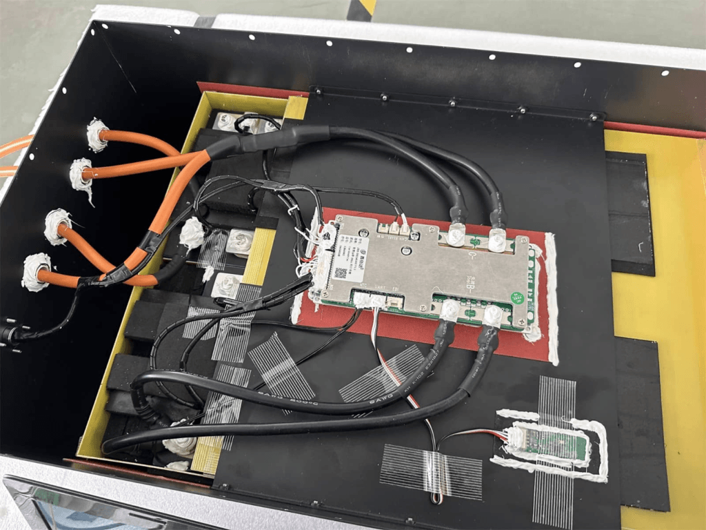
Step 7: BMS Installation and Wiring
The BMS installation is the most detail-sensitive step in the entire build. The cell tap wires must be connected in exactly the right order. The thermistors must be mounted in the right places. The power terminals must be connected in the right sequence.
Before starting this step, read the BMS wiring diagram for your specific model. Not the generic diagram from a YouTube video. The actual diagram for your unit. Different BMS models number their cell tap connections differently.
Wiring Step
Procedure and Detail
Engineering Notes
Step 1: Cell tap wire connection
Connect the BMS cell tap wires to each cell junction in order, from Cell 1 negative (the most negative point in the pack, also B-) through to Cell 16 positive (the most positive point, also B+). Follow the BMS wiring diagram exactly. Cell 1 wire connects to the negative terminal of Cell 1. Cell 2 wire connects to the junction between Cell 1 positive and Cell 2 negative. Continue through to Cell 16.
CRITICAL: Wrong cell tap connection order is the most common BMS damage cause on first assembly. The BMS IC measures differential voltages across each cell. If tap wires are connected in the wrong order or skipping a cell, the differential voltage presented to the IC can exceed its maximum input, permanently damaging the cell monitoring circuit. Verify the wiring diagram for your specific BMS model before connecting.
Step 2: Thermistor placement
Mount the first thermistor directly on the surface of the middle cells in the pack (cells 8 and 9 position). Mount the second thermistor on the BMS MOSFET board area. If four thermistors are available: two on cells at different positions in the stack, two on the BMS board.
The thermistors closest to the centre of the cell stack catch the highest temperature point. The MOSFET thermistor protects the BMS hardware from thermal damage. Do not mount thermistors on the busbar or enclosure wall; they must contact cell surfaces for accurate readings.
Step 3: B+ connection
Connect the B+ cable (from the most positive cell terminal) to the BMS B+ terminal. This cable carries full pack voltage and full charge/discharge current. Use the correct gauge cable calculated in the cable sizing section (50mm2 for 150A at 1 metre).
Do not connect B+ until all cell tap wires are connected. With B+ connected and tap wires incorrect, the BMS may power up and attempt to read cell voltages through the wrong connections, causing immediate IC damage.
Step 4: B- connection
Connect the B- cable (from the most negative cell terminal) to the BMS B- terminal. The current shunt is typically on the B- line inside the BMS.
B- is the current sense path. The shunt resistance here is very low (milliohms) to minimise voltage drop, but correct connection is essential for accurate current measurement.
Step 5: P+ and P- connection
Connect P+ to the inverter battery positive input (via pre-charge circuit and ANL fuse). Connect P- to the inverter battery negative input. P+ and P- are the load/charger side of the BMS MOSFETs.
P- is often the same terminal as B- in common-port designs. For separate-port designs, P+ and C+ are separate terminals. Confirm with the BMS wiring diagram before connecting.
Step 6: RS485 communication wiring
Connect BMS RS485 A terminal to inverter RS485 A terminal. Connect B to B. Add a GND wire between the two devices. Use a twisted pair cable. Keep the communication cable run physically separate from the power cables to avoid electromagnetic interference.
A and B polarity matters. If communication fails after correct configuration, swap A and B and retry. Wrong polarity does not damage hardware.
POWER-UP SEQUENCE MATTERS
Do not connect B+ until all cell tap wires are correctly connected and verified. Connect cell tap wires first, verify them against the wiring diagram, then connect B+. If you connect B+ first and then discover a tap wire is in the wrong position, the BMS has already powered up and may have read an incorrect cell voltage through the wrong channel. Disconnect B+, correct the tap wires, reconnect B+.
Step 8: BMS Configuration
The JK BMS ships with factory default settings that are set for a global average user. For a Nigerian off-grid solar installation, every protection threshold needs to be configured to match both the specific cells and the local operating conditions.
Open the JK BMS Bluetooth app on your phone. Pair with the BMS. Navigate to the protection settings and configure every parameter in the following table before the first charge cycle.
BMS Parameter
Setting
Notes
Cell overvoltage protection (OVP)
3.65V
Standard LiFePO4 charge termination voltage. Do not set higher.
OVP recovery voltage
3.55V
10mV hysteresis gap prevents rapid re-trip after reset.
Cell undervoltage protection (UVP)
2.80V
Conservative for daily cycling. Protects cycle life by avoiding the bottom 10% of the LiFePO4 discharge curve.
UVP recovery voltage
3.00V
Requires meaningful recharge before discharge path reconnects.
Charge overcurrent protection (OCP-C)
0.5C rate
For 200Ah cells: 0.5C = 100A. Set charge OCP at 100A.
Discharge overcurrent protection (OCP-D)
150% of max inverter demand
108.7A x 1.5 = 163A. Set at 160A to allow brief load peaks.
Charge overtemperature hard cutoff
50 degC
Nigerian condition specific. Global default (55-60 degC) is not conservative enough for a Lagos generator room.
Charge overtemperature soft limit
40 degC
Begin reducing CCL at 40 degC. Gradual current reduction prevents abrupt mid-charge disconnects.
Discharge overtemperature hard cutoff
65 degC
Cells under load heat faster than at rest. 65 degC cell surface is the safe limit.
Short circuit protection
Factory set (hardware comparator)
Verify response time under 200 microseconds from datasheet. Not configurable on most units.
Active balance start threshold
10mV
Detects early LiFePO4 imbalance in the flat voltage region before it compounds.
Active balance current
2A
Maximum correction speed. Reduce to 1A if enclosure runs chronically above 45 degC ambient.
Balance mode
Charging only (top balance)
Sufficient for daily solar cycling. Rest balancing not required for this application.
RS485 protocol
Deye variant
Confirm with supplier that firmware version is compatible with your specific Deye model.
RS485 baud rate
9600 bps
Standard for Deye, Growatt, Solis.
SOC calibration
Reset to 100% after first full charge
Establishes the coulomb counting baseline. Do this once after the initial top balance charge.
The engineering rationale behind each of these specific values is covered in our article on BMS protection explained. The OTP settings in particular are specific to Nigerian conditions and differ from global defaults.
KEY TAKEAWAY
A BMS running on factory defaults is not correctly configured. The 15 minutes you spend configuring thresholds in the app determines whether the pack is optimised for your specific cells and your specific installation environment.
Step 9: Commissioning the Pack
Commissioning is the process of verifying that everything you have built and configured is working correctly before handing the system over to daily service. Do not skip any commissioning step. A problem discovered at commissioning costs you 30 minutes to fix. The same problem discovered six months later costs you a site visit and possibly a degraded pack.
Commissioning Stage
Procedure
Pre-power checks
1. Verify all 16 cell tap wires are connected in the correct order. 2. Verify thermistors are mounted correctly on cell surfaces. 3. Verify all busbar connections are torqued to 4 to 6 Nm. 4. Verify ANL fuse is installed in the holder. 5. Verify RS485 cable is connected at both BMS and inverter ends. 6. Verify pre-charge circuit is in place between P+ and inverter DC positive.
Power-up sequence
1. Power up BMS by connecting B+ (fuse in place). 2. Open BMS Bluetooth app. Verify all 16 cell voltages reading between 3.62 and 3.65V. 3. Verify temperature readings show ambient temperature values. 4. Verify no fault codes are active in the BMS app. 5. Power up the inverter. Verify no hard fault on startup.
Communication verification
1. In inverter menu navigate to Battery Settings. Set battery type to correct BMS protocol. 2. Verify inverter display shows battery SOC as a percentage, not a voltage. 3. Cross-reference BMS app SOC against inverter display. Should agree within 3 to 5%. 4. If inverter shows voltage only: check RS485 A/B polarity and baud rate, confirm battery brand selection.
First charge cycle
1. Allow inverter to charge battery through a complete charge cycle. 2. During CV phase, watch all 16 cell voltages converging toward 3.65V in BMS app. 3. Watch active balance current indicator. Should show non-zero current if cell delta exceeds 10mV. 4. Record cell voltages at end of CV phase (when charge current drops below 5A). This is your commissioning baseline.
First discharge cycle
1. Run system through a complete discharge cycle to UVP cutoff. 2. Record which cell triggers cutoff and at what voltage. 3. Read final cell voltages in BMS app. All should be within 50mV of each other on a fresh pack. 4. If one cell is over 100mV below the others, investigate before continuing.
30-day performance check
1. Read cell voltage spread at end of CV phase. Should be under 30mV with active balancing. 2. Check fault log for OVP, UVP, OTP, or OCP events and investigate any found. 3. Measure MOSFET surface temperature under peak load. Should not exceed 55 degC. 4. Verify SOC agreement between BMS app and inverter display within 5%.
For a complete system-level commissioning protocol covering the inverter, MPPT controller, and BMS communication together, our hybrid solar system commissioning checklist covers the full 10-stage procedure.
Step 10: Enclosure Design and Final Installation
The physical enclosure determines the thermal environment the pack operates in for its entire service life. A well-designed enclosure maintains the temperature differential between the hottest and coolest cell in the stack below 5 degC. A poorly designed enclosure can create 15 to 20 degC gradients that drive accelerated differential aging and faster capacity loss.
Enclosure Requirements
Airflow path: Plan a clear airflow path across the cells, entering at the bottom of the enclosure and exiting at the top. Cells should not be packed so tightly that air cannot circulate between them.
BMS placement: Mount the BMS on the enclosure wall adjacent to the cell stack, not on top of or under the cells. Heat from the cells rises. BMS heat adds to what the thermistor reads. Mounting the BMS where it adds heat to the thermistor location gives inflated temperature readings.
Cable management: Route power cables along the bottom of the enclosure, away from the BMS PCB and thermistors. Communication cables route separately from power cables to avoid EMI coupling.
Ventilation: In a Lagos generator room, passive ventilation is often insufficient during the dry season. Add a small 12V DC fan (80 to 120mm) controlled by a temperature switch to provide forced airflow when enclosure temperature exceeds 35 degC.
Fuse accessibility: The ANL fuse holder must be accessible for inspection and fuse replacement without disassembling the pack.
Label everything: Cell polarity markers on each busbar, cable function labels on every cable, pack voltage and capacity on the enclosure exterior, BMS model and communication protocol on the BMS location.
Pre-Charge Circuit Installation
The pre-charge circuit connects between the battery P+ terminal and the inverter DC positive input. When the inverter is first powered up, current flows through the pre-charge resistor rather than directly from the battery, limiting the inrush current that would otherwise trip the BMS OCP.
The pre-charge resistor calculation: R = V_battery / I_limit. Where I_limit is the maximum inrush current we want to allow (typically 10 to 20A for a smooth ramp). For a 58.4V pack and 10A limit: R = 58.4 / 10 = 5.84 ohms. Use a 10 ohm, 20W resistor for safety margin.
The pre-charge relay closes after 500ms to 1 second, bypassing the resistor and allowing full current flow for normal operation. Use a 24V or 12V coil relay controlled by the inverter’s auxiliary output or a simple timer relay circuit.
The inverter startup surge problem and the full range of pre-charge solutions are covered in our how to size a BMS correctly article, in the startup surge section.
The Six Mistakes That Destroy DIY LiFePO4 Packs
Every mistake in this section is documented from real field observations. None of these is hypothetical. All of them have occurred in Nigerian solar installations, and all of them have cost someone money.
Common Mistake
What Goes Wrong
How to Avoid It
Skipping capacity testing and using cells directly from packaging
Without testing, you do not know the actual capacity of each cell. A 200Ah rated cell may deliver 187Ah or 213Ah. A 200Ah pack with cells ranging from 187 to 213Ah will develop significant imbalance within the first 100 cycles as the low-capacity cells diverge from the high-capacity cells.
Test every cell at 0.2C. Discard outliers. Match cells within 2% of each other before assembly.
Skipping top balance and assembling straight from capacity test state
After the capacity test, cells are at varying states of charge (all near 2.50V from the discharge test). Assembling them in series at different SOC levels means the first charge cycle pushes the highest-SOC cells to OVP before the lowest-SOC cells are even half full. The first cycle is already damaging.
Top balance all cells to 3.65V in parallel before series assembly. This is not optional.
Using undersized cables between cells and BMS
A 25mm2 cable carries 150A with a voltage drop of 0.052V per metre. Not a disaster at 0.5 metre. But at 2 metres, the voltage drop is 0.1V, meaning the BMS is seeing 0.1V less than the actual cell voltage. This offsets the OVP reading and can allow cells to be overcharged without the BMS detecting it correctly.
Calculate cable sizes using the formula V = I x (rho x L / A). Use 50mm2 for 150A at runs up to 3 metres.
No pre-charge circuit between P+ and inverter
Every inverter startup causes a capacitor inrush current spike that can reach 300 to 500A for 10 to 100 milliseconds. Without a pre-charge circuit, this spike either trips the BMS OCP protection at every startup, or trains the installer to raise the OCP threshold permanently to accommodate it, destroying overcurrent protection.
Install a pre-charge circuit: a 50 to 100 ohm, 10W resistor with a relay bypass that engages after 500ms to 1 second. Wire it between P+ and the inverter DC positive input.
Cell tap wires connected in wrong order
Wrong tap wire order presents incorrect differential voltages to the BMS cell monitoring IC. The IC may be immediately damaged on power-up, or may report false cell voltages that mislead the BMS protection logic. Either way, the BMS must be replaced and the pack must be disassembled for rewiring.
Follow the BMS wiring diagram exactly. Lay out all 16 tap wires numbered before connecting. Have a second person verify the order before powering up.
Not configuring BMS thresholds before first charge
A JK BMS with factory default thresholds may have OVP set to 3.70V or higher, UVP set to 2.50V, and charge OTP set to 60 degC. These are not optimal for daily cycling in Nigerian conditions. The first charge cycle may overcharge the cells slightly, the first discharge may deep-discharge slightly, and the enclosure may run hot without triggering OTP.
Configure all thresholds through the BMS app before the first charge cycle. The configuration table in this article gives the correct values.
For the broader catalogue of system-level mistakes that cause battery systems to fail before year 2, our article on why most solar battery systems fail before year 2 documents the full failure pattern including both cell-level and system-level errors.
Frequently Asked Questions
How many cells do I need to build a 48V 200Ah LiFePO4 battery?
You need 16 cells in series (16S) for a 48V nominal LiFePO4 pack. Each LiFePO4 cell has a nominal voltage of 3.2V. 16 cells x 3.2V = 51.2V nominal, which is the standard 48V LiFePO4 pack voltage. For 200Ah capacity with a single series string, you need 16 cells each rated at 200Ah. The resulting pack has a gross energy of 200Ah x 51.2V = 10.24 kWh. At 80% depth of discharge, usable energy is approximately 8.2 kWh.
What tools do I need to build a LiFePO4 battery pack?
Essential tools: a torque wrench set to 4 to 6 Nm for cell terminal bolts, a cell capacity tester or power supply with coulomb counting capability, a digital multimeter for voltage verification, wire strippers and crimping tools for cable lug preparation, an IR thermometer for thermal checks during commissioning, a single-cell charger or power supply for the top balance procedure, and a phone with the BMS Bluetooth app installed and tested before assembly begins. Optional but strongly recommended: a thermal imaging camera for commissioning checks and an oscilloscope for verifying BMS SCP response time.
Can I build a LiFePO4 battery without testing cells first?
You can, but you should not. Untested cells from the same production batch may vary by 3 to 8% in actual capacity. A cell delivering 184Ah in a nominally 200Ah pack will diverge from a 212Ah cell within 200 cycles of daily deep cycling, reducing usable pack capacity and increasing BMS trip frequency. Testing takes 6 to 8 hours per cell at 0.2C but it is the difference between a pack that performs well for 3,000 cycles and one that starts showing capacity loss after 300.
Do I need to top balance cells before assembling a LiFePO4 pack?
Yes. Top balancing before assembly means starting the first series charge cycle with all cells at the same state of charge. Without it, cells at different SOC levels are connected in series and the first charge pushes the highest-SOC cells to OVP before the lowest-SOC cells are even half full. This creates immediate stress on the leading cells and establishes an imbalance pattern that compounds over the following months. Top balance once before assembly and the BMS active balancer maintains the alignment from there.
How long does it take to build a 48V 200Ah LiFePO4 battery pack?
Budget 2 to 3 days for a proper build. Day 1: capacity test all 16 cells (6 to 8 hours per cell at 0.2C, but you can test 3 to 4 cells in parallel on separate testers). Day 2: top balance all cells in parallel (4 to 6 hours), then series assembly, busbar installation, BMS cell tap wiring, and power cable connection. Day 3: BMS configuration, communication verification with the inverter, first charge cycle observation, first discharge cycle observation. Rushing any of these stages produces a pack that underperforms or fails prematurely.
What BMS should I use for a DIY 48V 200Ah LiFePO4 pack in Nigeria?
For a 48V 200Ah pack cycling daily with a Deye, Growatt, or Solis hybrid inverter in Nigeria: JK BMS active balancer 16S, 200A, RS485 variant. Configure OVP at 3.65V, UVP at 2.80V, charge OTP at 50 degC, balance start threshold at 10mV, balance current at 2A. Connect the RS485 cable and verify SOC communication before placing in service. For Victron-based systems: JK BMS CAN variant or a sealed Pylontech unit.
What is the difference between 16S1P and 16S2P battery configurations?
16S1P means 16 cells in series, 1 cell per position (single string). Pack voltage is 51.2V nominal, pack capacity is the capacity of one cell. 16S2P means 16 cells in series with 2 cells in parallel at each position (double string). Pack voltage is still 51.2V nominal, but pack capacity doubles. A 16S2P pack using 200Ah cells has 400Ah total capacity. The BMS still manages 16 voltage points (one per parallel group) but must handle twice the current. For a 16S2P pack, the BMS current rating must accommodate twice the single-string current.
Can I use different brands of cells in the same pack?
No. Cells from different manufacturers have different internal resistance profiles, different capacity tolerances, and different aging characteristics even when nominally rated the same. Mixing brands creates immediate mismatch that compounds aggressively. Use cells from the same manufacturer, the same model, and ideally the same production batch. If cells from a batch must be replaced after failure, replace with cells from the same batch or accept the need to test and match the replacement cell carefully before installation.
I am Engr. Ubokobong Ekpenyong, a solar specialist and lithium battery systems engineer with over five years of hands-on experience designing, assembling, and commissioning off-grid solar and energy storage systems. My work focuses on lithium battery pack architecture, BMS configuration, and system reliability in off-grid and high-demand environments.
Contains information related to marketing campaigns of the user. These are shared with Google AdWords / Google Ads when the Google Ads and Google Analytics accounts are linked together.
90 days
__utma
ID used to identify users and sessions
2 years after last activity
__utmt
Used to monitor number of Google Analytics server requests
10 minutes
__utmb
Used to distinguish new sessions and visits. This cookie is set when the GA.js javascript library is loaded and there is no existing __utmb cookie. The cookie is updated every time data is sent to the Google Analytics server.
30 minutes after last activity
__utmc
Used only with old Urchin versions of Google Analytics and not with GA.js. Was used to distinguish between new sessions and visits at the end of a session.
End of session (browser)
__utmz
Contains information about the traffic source or campaign that directed user to the website. The cookie is set when the GA.js javascript is loaded and updated when data is sent to the Google Anaytics server
6 months after last activity
__utmv
Contains custom information set by the web developer via the _setCustomVar method in Google Analytics. This cookie is updated every time new data is sent to the Google Analytics server.
2 years after last activity
__utmx
Used to determine whether a user is included in an A / B or Multivariate test.
18 months
_ga
ID used to identify users
2 years
_gali
Used by Google Analytics to determine which links on a page are being clicked
30 seconds
_ga_
ID used to identify users
2 years
_gid
ID used to identify users for 24 hours after last activity
24 hours
_gat
Used to monitor number of Google Analytics server requests when using Google Tag Manager
1 minute
You can find more information in our Cookie Policy and .


")


")
")


