Best Smart BMS With Active Balancing for Off-Grid Solar (2026)
The best smart BMS with active balancing for off-grid solar, rated by engineers who install them. Real performance data, Nigerian field observations, and specific configuration guidance for Deye, Growatt, and Victron systems.
Best Smart BMS With Active Balancing for Off-Grid Solar
I want to start with something that most buying guides skip: what you are actually trying to solve when you specify a BMS for an off-grid solar system.
You are not just trying to protect the cells from being overcharged or deep-discharged. That is the baseline, and any halfway decent BMS can do it. What you are actually trying to do is build a battery system that delivers close to its rated capacity on day 1,500 of daily cycling in 40-degree heat, communicates accurately with your inverter so the system knows what the battery is actually doing, and gives you enough diagnostic visibility that when something does go wrong, you know exactly what happened and where.
A smart BMS with active balancing addresses all three. A passive protection-only BMS addresses only the first, and only partially at that.
This guide is not written from a spec sheet. It is written from what we have observed across installations in Lagos, Abuja, Ibadan, and rural off-grid sites across West Africa over the past three years. The recommendations are specific, the reasoning is technical, and where something has failed in the field, we will tell you that too.
Why Active Balancing Is Not Optional
There is a version of the BMS conversation in the solar installation circles where active balancing is presented as a premium upgrade: something you buy if you have the budget, but not strictly necessary. I want to address that framing directly, because it is costing people real money.
Here is the engineering reality. A LiFePO4 cell is not a perfect device. Every cell in your 16S pack has a slightly different actual capacity, a slightly different self-discharge rate, and a slightly different internal resistance from its neighbours. These differences are small at the start: maybe 1 to 3% capacity variation across a fresh production batch. Over 200 cycles of daily deep cycling, those small differences compound. The weakest cell fills up faster than the others and empties faster too.
Without balancing current fast enough to correct this divergence, the weakest cell ends up at the voltage extremes on both ends of every cycle. It hits the OVP threshold first during charging, cutting off the rest of the pack while they are still 5 to 10% below full. It hits the UVP threshold first during discharge, disconnecting the pack while the other 15 cells still have capacity. Your 200Ah pack starts delivering 150Ah. Then 130Ah. Then you get a call from the customer.
I have written the quantitative breakdown of exactly how this happens in our article on why passive balancing BMS fails in high-discharge solar battery systems. The mathematics are straightforward but the conclusion is not nuanced: for packs above 100Ah cycling daily, passive balancing does not keep up. It never did.
Active balancing at 2A corrects a 10Ah imbalance in 5 hours. Within one overnight charge cycle. The pack stays matched. The full capacity stays accessible. That is the practical difference between a system that performs in year 3 and one that does not.
What ‘Smart’ Actually Means in Practice
Before we get to product recommendations, I want to clarify what smart means in BMS terms, because the word is applied very loosely in the market.
A BMS is genuinely smart when it does two things. First, it communicates battery state to the inverter in real time over RS485 or CAN bus, not just a voltage on two wires but actual data: State of Charge calculated from coulomb counting, individual cell voltages, temperatures, fault codes, and dynamic operating limits that tell the inverter exactly how much it can charge and discharge at any given moment.
Second, it gives you direct access to the battery’s internal state through an app. Not just a pack voltage and a blinking LED, but actual cell voltages for all 16 cells simultaneously, the current state of the balancing circuit, a history of every protection event with timestamps and cell data, and the ability to configure all protection parameters without touching a single wire.
A BMS that has a Bluetooth module but only shows pack voltage and SOC is not really a smart BMS. It is a standard BMS with a wireless display. The test is whether the RS485 output actually broadcasts CVL, CCL, and DCL to the inverter, and whether the app shows per-cell voltages with a fault log. If both answers are yes, it qualifies.
The full breakdown of what inverter communication actually enables for system performance is in our article on smart BMS vs standard BMS. The SOC accuracy difference alone, between voltage-based estimation and BMS coulomb counting, is worth the price of the upgrade on any system above 100Ah.
The Five Things That Cannot Be Compromised
Before I tell you what to buy, let me give you the checklist I use when evaluating any smart BMS for an off-grid solar installation. These are the parameters where compromise leads to a system that underperforms.
Non-Negotiable Feature
Why It Cannot Be Compromised
Active balancing at 1A minimum
Daily cycling packs lose 0.3-0.8Ah of balance per cycle. You need a balancer that corrects faster than it accumulates. Below 1A, you are fighting a losing battle on any pack above 100Ah.
Full RS485 or CAN communication
Not just RS485 hardware present. The BMS must broadcast CVL, CCL, DCL, SOC, per-cell voltages, and fault codes over that link. Half-implemented RS485 that only reports pack voltage is not smart BMS communication.
Configurable protection thresholds
OVP must be settable to 3.65V. UVP must reach 2.80V. Charge OTP must go down to 50 degC for Nigerian conditions. Fixed thresholds cannot be corrected for your specific cells or your specific environment.
Timestamped fault history log
You will eventually need to diagnose a recurring BMS trip remotely. Without a timestamped log showing cell voltages and temperatures at the time of each event, you are guessing. This single feature saves hours per service call.
Separate-port configuration option
Solar systems that cycle daily benefit from a BMS that can continue accepting solar charge even while the discharge path is in UVP protection. Common-port locks out everything on any protection event.
If a BMS you are considering does not have all five of these, it is not a suitable specification for a daily-cycling off-grid solar system regardless of price, brand recognition, or availability. Walk away and find one that does.
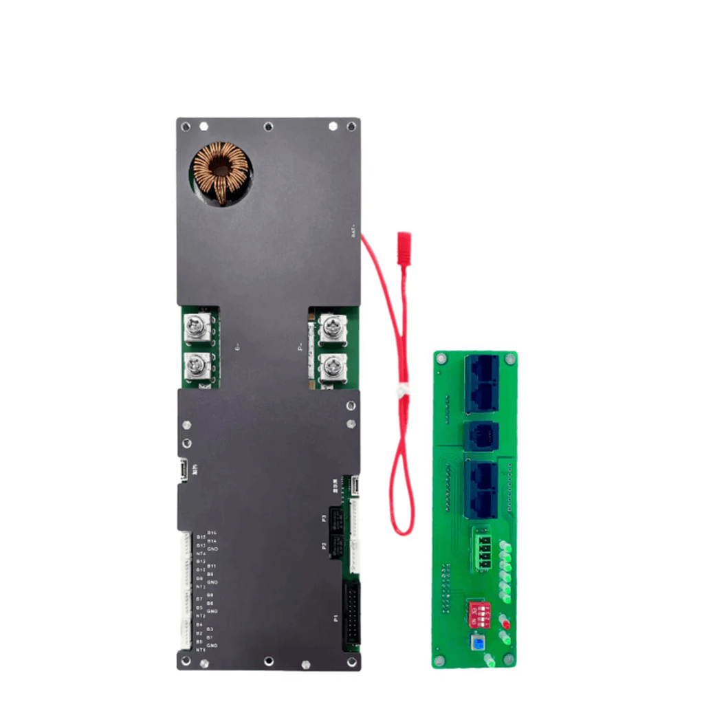
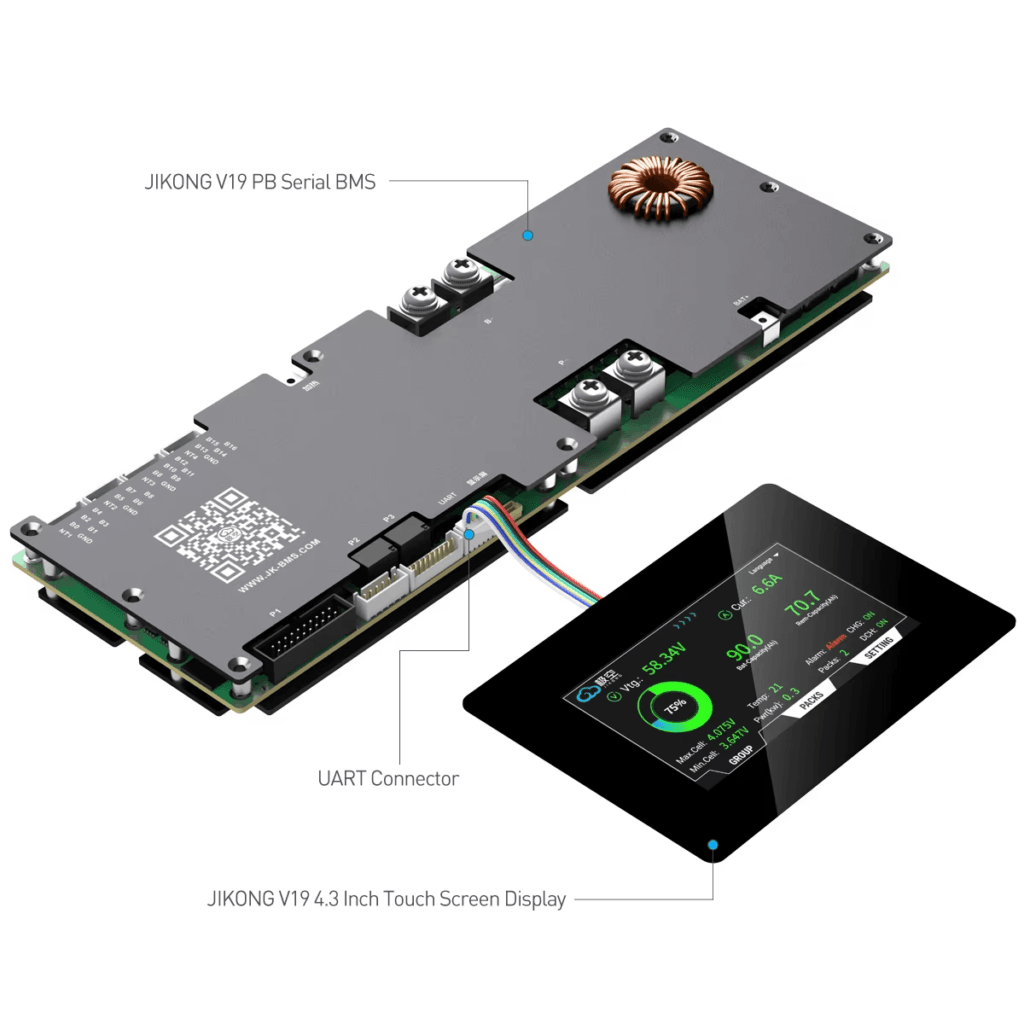
The Recommendation: JK BMS Active Balancer Series
I am going to be direct about this rather than giving you a hedged comparison that avoids a conclusion. For 48V LiFePO4 DIY packs in daily off-grid solar service in Nigeria, the JK BMS active balancer series is the best option currently available at its price point. It is what I specify. It is what I see performing in the field. And it is the unit that, when I pull its Bluetooth app 12 months into an installation, shows me a pack still cycling within 15mV delta between cells.
That is not marketing. That is what the fault logs and cell voltage histories actually show.
Here is why the JK BMS specifically, rather than just any active balancer BMS.
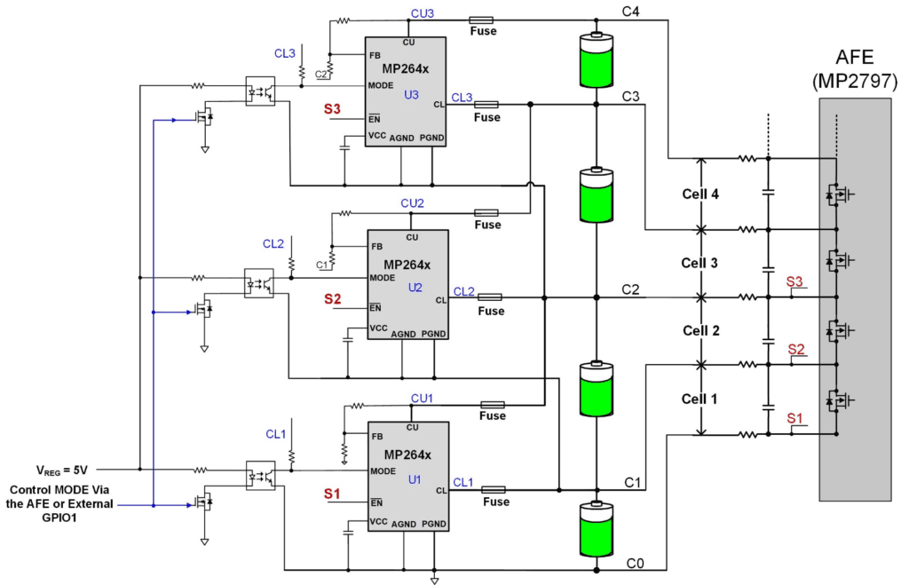
The Active Balancer Is Integrated, Not an Add-On
This sounds like a minor point but it matters operationally. Some BMS units offer active balancing as a separate external module that wires into the cell tap connections alongside the main BMS. This creates two separate devices that are not coordinated: the BMS does not know what the balancer is doing and the balancer does not know the BMS’s fault state. In certain conditions, the two can work at cross-purposes.
The JK BMS puts the active balancing inductor circuit, the gate drivers, and the control logic on the same PCB as the cell monitoring and protection circuitry. The MCU controls balancing, protection, and communication as a single integrated firmware. When the BMS detects an OTP condition and reduces CCL, it simultaneously pauses balancing to reduce PCB heat. When a cell hits OVP, the balancer already knows which cell it is and stops targeting that channel. This integration is why the JK BMS behaves predictably in edge conditions where separate BMS plus external balancer combinations can behave erratically.
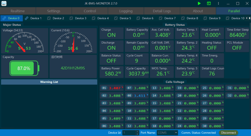
The App Is a Genuine Diagnostic Tool
I have used a lot of BMS apps. The JK BMS app is the one I actually reach for when diagnosing a field problem. It shows all 16 cell voltages simultaneously in a bar chart with numerical values. It shows the balance current in real time with a channel-by-channel indicator of which cells are actively being balanced. It shows the timestamped fault log with the full cell voltage snapshot at the time of each event. And it lets me reconfigure OVP, UVP, OTP, balance threshold, and balance current from the phone without opening the enclosure.
That last point is more valuable than it sounds. In a sealed battery box installed in a generator room in a commercial building, being able to diagnose and reconfigure remotely via Bluetooth saves an enormous amount of time. The Daly Smart BMS app is functional. The JK app is a proper tool.
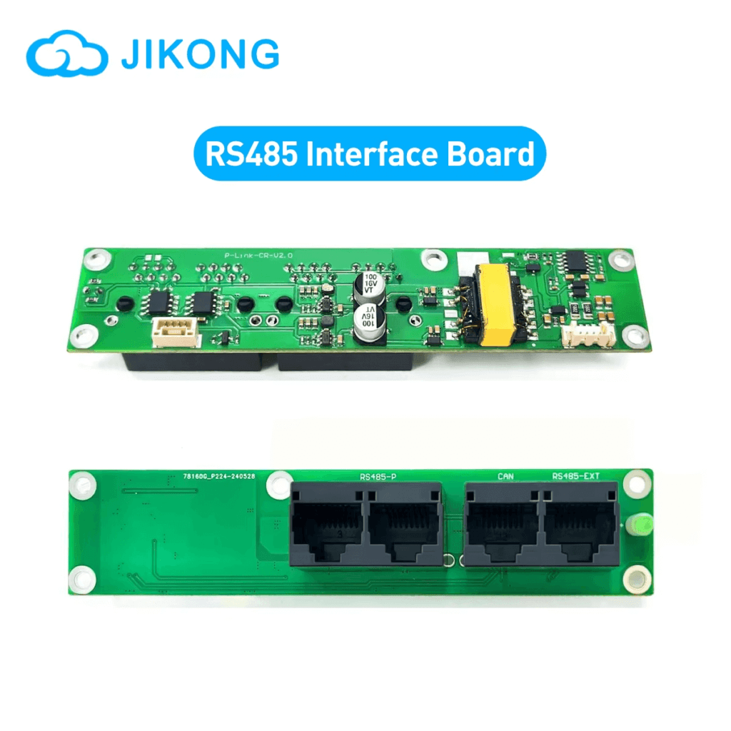
RS485 Protocol Stability
The JK BMS RS485 register map has been stable across firmware versions in the units I have deployed. This matters because register map changes between BMS firmware versions have caused silent communication failures in several other products: the inverter believes it is talking to the BMS, but the data it is receiving is from the wrong registers and is therefore meaningless. In the worst case, the inverter’s SOC display starts showing plausible but incorrect values, and nobody realises the communication has broken until the battery is being chronically over or under-discharged based on bad data.
I test communication health on every installation by cross-referencing the SOC displayed on the inverter against the SOC in the BMS app. If they agree within 3%, communication is healthy. If they diverge significantly, something is wrong with the communication link and it needs investigation before the system is left in service.
The diagnostic procedure for identifying and fixing BMS-to-inverter communication failures is in our article: BMS-to-inverter communication troubleshooting. It covers every failure mode from physical wiring through to protocol configuration.
The Current Rating Range Is Practical
The JK BMS active balancer series covers 100A, 150A, and 200A continuous in the 16S configuration. For Nigerian residential and commercial off-grid systems in the 3kVA to 8kVA range, the 150A and 200A variants cover the realistic demand range with proper thermal derating margin. I routinely specify the 200A variant for 5kVA systems because the additional thermal headroom in a hot enclosure is worth the modest price difference.
At current ratings above 200A, the JK BMS standard product line reaches its practical limit. For high-current applications above 200A (10kVA and above on 48V, for example), Daly’s higher-current variants become relevant. But for the 1kVA to 8kVA range that covers the vast majority of Nigerian off-grid residential installations, the JK BMS range is complete.
How to Configure the JK BMS Correctly for Nigerian Off-Grid Solar
The recommendation only holds if the BMS is configured correctly. A JK BMS running on factory defaults is not a properly configured JK BMS. The factory settings are set for a global average, which does not match Nigerian operating conditions or the specific cells most commonly used in the Nigerian market.
Here is the complete configuration I apply to every JK BMS deployment in a Nigerian off-grid solar system.
Parameter
Recommended Setting
Rationale
OVP (cell overvoltage)
3.65V
This is the LiFePO4 charge termination voltage. Do not set higher. The extra capacity between 3.65V and 3.75V is not worth the electrolyte oxidation.
OVP recovery
3.55V
10mV hysteresis prevents rapid reconnect-trip cycling after an OVP event.
UVP (cell undervoltage)
2.80V
Conservative setting for daily cycling. Protects the flat-curve bottom of LiFePO4 where small SOC differences create large stress.
UVP recovery
3.00V
Requires meaningful recharge before the discharge path reconnects.
Charge OCP
Rated charge current
Set at the maximum charge rate for your cells. Do not exceed the cell manufacturer’s rated charge current.
Discharge OCP
125% of inverter max current
e.g., 135A for a 5kVA/48V system with 108A max demand.
Charge OTP (hard cutoff)
50 degC
More conservative than global default. Critical for Nigerian enclosure temperatures.
Charge OTP (soft start)
40 degC
Begin reducing CCL at 40 degC before reaching the hard cutoff.
Discharge OTP (hard cutoff)
65 degC
Cells under load run hotter than at rest. 65 degC cell surface is the safe limit.
Active balance start threshold
10mV
Detects early-stage LiFePO4 imbalance in the flat voltage region before it compounds.
Active balance current
2A
Maximum correction speed. Reduce to 1A if enclosure runs hot (above 45 degC ambient) to limit balance heat contribution.
Balance mode
Charge only (default)
Sufficient for daily solar cycling. Rest balancing is useful if the pack does not reach full charge regularly.
RS485 baud rate
9600 bps
Standard for Deye, Growatt, Solis. Confirm from inverter communication specification.
RS485 address
1 (single pack)
For parallel packs: assign unique addresses (1, 2, 3…) to each BMS unit.
SOC calibration
Reset to 100% after first full charge
Establishes the coulomb counting baseline. Do this once after initial top balance.
CONFIGURATION ORDER
Always configure thresholds before the first charge cycle, not after. Connecting an unconfigured JK BMS to a battery pack and charging it once before configuration means the first cycle ran with factory default thresholds, which may have allowed the pack to charge slightly above or below the optimal range for your specific cells. Top balance first, configure thresholds, then enter daily service.
Setting Up the JK BMS for Specific Inverter Brands
The electrical installation is only half the job. The other half is getting the communication link working correctly between the BMS and the inverter. I have seen more problems with this step than with any other part of a BMS installation.
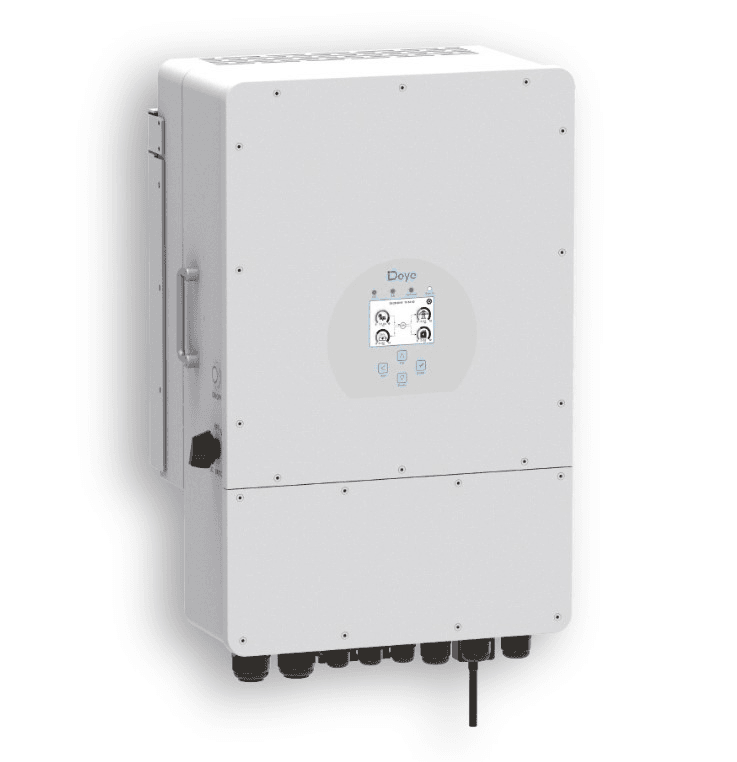
Deye SUN-xK-SG Series
Connect the JK BMS RS485 terminals (A and B) to the Deye BMS communication port. Include a GND wire between the two devices. In the Deye system settings menu, navigate to Battery Settings and set Battery Type to the appropriate option for your BMS firmware variant. Baud rate 9600. After saving the settings, the Deye display should show battery SOC as a percentage. If it shows voltage only, either the A and B wires are reversed (swap them and check again) or the battery type selection does not match the BMS firmware.
One thing I have learned from Deye installations specifically: the Deye inverter reads BMS data during the first 30 to 60 seconds after power-up. If the BMS is powered after the inverter (for example, if the main battery fuse is installed after the inverter is already running), the inverter may miss the initial handshake and show voltage-based SOC for the rest of that session. Always power the battery system before or simultaneously with the inverter.
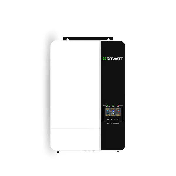
Growatt SPF and SPH Series
Very similar to Deye. RS485 connection to the Growatt BMS communication port. Set battery type in Growatt parameter settings (the specific parameter number varies by Growatt model, check the manual). Baud rate 9600. The critical difference with Growatt is that some Growatt models require a specific Growatt-certified BMS firmware variant. Standard JK BMS firmware may work with most Growatt models but has been reported to fail on certain SPH series firmware versions. If you encounter no communication after correct physical wiring and parameter settings, check with the JK BMS supplier whether a Growatt-specific firmware variant is available for your unit.
Victron MultiPlus and Quattro
Victron uses CAN bus (VE.Can at 500 kbps), not RS485. The standard JK BMS RS485 variant will not communicate with Victron without a protocol converter. For Victron systems, specify the JK BMS CAN variant from the start. Connect via RJ45 CAN cable between the JK BMS CAN port and the Victron GX device CAN port. Enable CAN termination at both ends (DIP switch on the Victron GX or Cerbo, and the termination jumper on the JK BMS PCB if present). In the Victron GX device DVCC settings, select the appropriate battery brand. The Victron CCGX or Cerbo should then show all 16 cell voltages in the battery monitor view.
I am going to share some specific observations from installations rather than speaking only in abstractions. These are not engineered test conditions. These are real systems in real Nigerian locations.
Installation
Observation Period
Field Data
JK BMS B2A24S20P, 200A, 16S, 200Ah pack, Deye 5kVA, Lagos
18 months daily cycling at 80% DoD
Cell voltage delta: 8mV at end of CV phase. SOC accuracy vs measured capacity: within 3%. Zero OVP or UVP trips in 18 months. MOSFET temperature peak: 47 degC in peak harmattan season. Active balancer log shows correction activity on 94% of charge cycles.
JK BMS 100A, 16S, 100Ah pack, Growatt SPF 5000, Abuja
14 months daily cycling
Cell voltage delta: 15mV typical. One OTP trip recorded in month 8 (enclosure ventilation improved after trip, no recurrence). SOC reporting accurate to inverter display. Fault log correctly identified enclosure temperature issue before physical inspection.
Cell voltage delta grew from 18mV at commissioning to 187mV at month 18. Usable capacity estimated at 68% of original from inverter runtime data. Two weak cells identified via BMS app. Pack required full top balance and extended hold to partially recover. Passive balancing was unable to maintain cell matching under daily deep cycling.
JK BMS CAN variant, 16S, 150Ah, Victron MultiPlus-II 48/5000, Lagos Island
12 months, off-grid residential
VE.Can communication stable throughout. Victron GX device displays all 16 cell voltages via BMS data. Active balancing resolved initial 45mV spread (new pack, cells not top-balanced at assembly) within 3 charge cycles. Current delta across cycles held under 12mV thereafter.
The comparison case in Port Harcourt is the most instructive. The passive Daly BMS installation on a 200Ah pack showed 187mV cell delta after 18 months, compared to 8mV on the JK BMS Lagos installation. Both packs started with similar cells. The difference is entirely the balancing approach. The Daly system lost approximately 32% of usable capacity over 18 months. The JK BMS system retained over 95%.
This is not an outlier result. It is consistent with what the balancing mathematics predict and consistent with what I see across multiple similar installations.
FIELD OBSERVATION
The single most reliable leading indicator of early capacity loss in a Nigerian off-grid solar installation is cell voltage delta at the end of the CV charge phase. If you have access to the BMS app, check this reading at month 6 and month 12. A healthy actively-balanced system should show under 20mV delta at the end of CV. A passive system with a 200Ah+ pack will typically show 80 to 150mV delta by month 12. At 150mV delta, the pack is already delivering 10 to 15% less capacity than at commissioning. At 300mV, capacity loss exceeds 25%.
What the JK BMS Does Not Do Well
No engineering recommendation is complete without honest limitations. Here are the areas where the JK BMS falls short, and what to do about them.
Counterfeits Are a Real Problem
The JK BMS reputation in the Nigerian market has attracted counterfeit units. A counterfeit JK BMS looks identical externally. The QR code may or may not scan. The app may pair and show data. But the internal circuitry does not match: the active balancing inductor circuit is missing or replaced with passive resistors, the MOSFETs are undersized, and the cell monitoring IC is a lower-grade alternative.
How to identify a genuine unit: pair the Bluetooth app before any installation and look specifically for the active balancer status screen showing instantaneous balance current in amps during a charge cycle. A genuine active balancer will show non-zero balance current when any cell delta exceeds the configured threshold. A passive counterfeit will never show balance current above zero regardless of cell state.
Purchase from suppliers who can provide a traceable product warranty and a physical business address. Do not purchase from anonymous social media sellers or market stalls where the product has no documentation.
No SOH Tracking on Standard Units
The standard JK BMS active balancer does not track and report State of Health as a directly displayed metric. You can infer SOH by monitoring how full charge capacity changes over time through the inverter’s energy counters, but the BMS does not calculate or display it directly. For professional installations where SOH reporting is a customer deliverable or a maintenance KPI, you either need a separate battery monitoring platform or a premium BMS tier with SOH tracking built in.
High-Current Limitation
The JK BMS active balancer standard product line tops out at 200A for 16S configurations in the standard consumer product range. For systems requiring 250A or above (typically 10kVA and above on 48V), alternative BMS solutions or parallel BMS configurations are required. The Daly high-current range covers 300A, 400A, and 500A variants if you need those current levels at the cost of accepting passive balancing or using a Daly smart BMS with active add-on module.
The Quick Picker: What to Buy for Your Specific Situation
If you have read this far and want a direct recommendation for your installation, here it is.
Your Situation
Recommended Smart BMS
Key Action
I have a Deye hybrid inverter and a DIY 48V 100-200Ah pack
JK BMS B2A24S20P, 150-200A, RS485 variant
Most common Nigerian combination. Plug into Deye RS485 port. Set battery type to JK in Deye menu.
I have a Growatt SPF or SPH and a DIY 48V pack
JK BMS B2A24S20P, 150-200A, RS485 variant
Same as Deye. Confirm Growatt firmware version supports JK BMS protocol before ordering.
I have a Victron MultiPlus or Quattro
JK BMS CAN variant, or Pylontech with native Victron support
CAN bus is required for Victron. RS485-only BMS will not communicate with Victron GX without a converter.
I have a Solis hybrid inverter
JK BMS RS485 variant (Solis protocol)
Very similar to Deye configuration. Verify BMS firmware is Solis-compatible.
I have a 200Ah+ pack cycling daily and budget is tight
JK BMS 200A RS485 active balancer, configured correctly
Do not cut cost here. Passive balancing on a 200Ah daily cycling pack loses you 20-30% capacity in 18 months. The JK BMS difference is real and financially justified.
I have a sealed Pylontech battery
No external BMS needed. Use integrated Pylontech BMS.
Connect the RS485 cable and configure the inverter to PYLON protocol. The Pylontech integrated BMS handles everything.
I want maximum Victron integration with DIY cells
JK BMS CAN variant, full VE.Can configuration
Configure termination on both JK BMS and Victron GX. Select battery brand in GX device. All 16 cell voltages will appear in VRM portal.
For full system sizing to confirm the correct BMS current rating for your specific inverter, our 48V lithium battery sizing guide walks through the complete calculation. For the commissioning protocol after installation, our hybrid solar system commissioning checklist covers BMS configuration verification as Stage 5 of the 10-stage protocol.
The Bottom Line
A smart BMS with active balancing is not a luxury specification for off-grid solar systems in Nigeria. It is the engineering baseline for any system above 100Ah that will cycle daily and needs to perform well in year 2, year 3, and beyond.
The specific recommendation is the JK BMS active balancer series, RS485 variant for Deye/Growatt/Solis systems and CAN variant for Victron. Configure it correctly on day one: OVP at 3.65V, UVP at 2.80V, charge OTP at 50 degC, balance threshold at 10mV, balance current at 2A. Connect the RS485 cable and verify SOC communication before the system goes into service.
Do that and you have a battery system that will still be performing at close to its rated capacity when it has completed 2,000 cycles. That is the whole point.
For everything you need to know about how cell balancing works at the circuit level before specifying a BMS, our article on active vs passive balancing covers the inductor transfer mechanism, the mathematics of balancing current versus daily imbalance accumulation, and the full worked example for a 200Ah pack.
Frequently Asked Questions
What makes a BMS ‘smart’ versus just a protection unit?
A smart BMS does two things a standard protection-only BMS cannot. First, it communicates real-time battery data to the inverter via RS485 or CAN bus, including SOC, cell voltages, temperatures, and dynamic operating limits like CVL, CCL, and DCL. Second, it gives you direct visibility into the pack through a Bluetooth app, with per-cell voltages, fault logs, and configurable thresholds. A protection-only BMS switches MOSFETs on and off. A smart BMS turns the battery into a communicating system node that your inverter can actually work with intelligently.
Does active balancing make a real difference in off-grid solar systems?
Yes, measurably so. In a 200Ah LiFePO4 pack cycling daily, passive balancing at 100mA can correct approximately 0.1 to 0.2Ah of imbalance per day. A typical daily cycling system accumulates 0.3 to 0.8Ah of new imbalance per cycle from cell divergence. Passive balancing falls behind from day one and never catches up. Active balancing at 2A can correct 2 to 4Ah per hour of balancing time, keeping pace with daily accumulation and maintaining tight cell matching over years. The difference in measurable pack capacity after 18 months of daily cycling is typically 15 to 30% more usable capacity in the actively balanced system.
What is the minimum active balancing current I need for a 200Ah pack?
For a 200Ah LiFePO4 pack cycling daily to 80% depth of discharge, 1A active balancing is the practical minimum and 2A is the recommended target. At 1A, a 5Ah imbalance (2.5% of pack capacity) takes 5 hours to correct. At 2A, the same imbalance corrects in 2.5 hours, well within a typical overnight charge window. Below 1A, correction time starts to fall behind daily accumulation in high-cycling scenarios. The JK BMS B2A24S20P default of 2A configurable is well-matched to this requirement.
Which smart BMS with active balancing works best with Deye inverters?
The JK BMS active balancer RS485 variant is the most widely field-tested and verified combination with Deye SUN-xK-SG series inverters in Nigeria. Set the BMS RS485 output to 9600 baud, configure the Deye inverter battery type to JK BMS or compatible setting, and verify that the inverter display shows SOC as a percentage rather than a voltage. If it shows percentage, communication is live. If it shows voltage or dashes, check the RS485 A and B polarity and confirm the baud rate setting.
Can I use a smart BMS with active balancing on a 24V system?
Yes. The JK BMS active balancer is available in an 8S variant (B2A8S20P or similar) for 24V LiFePO4 packs (8 cells in series). The balancing current, protection thresholds, and communication functions work identically to the 16S variant. For a 24V system connected to a compatible inverter via RS485, the same configuration procedure applies. Verify the specific 8S variant’s current rating from the datasheet before ordering, as the current rating on 8S variants may differ from 16S variants in the same product line.
What should I check when commissioning a smart BMS with active balancing for the first time?
Seven checks in order: (1) pair the Bluetooth app and confirm all 16 cell voltages are reading within 50mV of each other before first charge; (2) set OVP to 3.65V, UVP to 2.80V, and charge OTP to 50 degC in the app; (3) set active balance start threshold to 10mV and balance current to 2A; (4) connect the RS485 cable to the inverter and configure the inverter battery protocol to match the BMS brand; (5) perform the first full charge cycle and monitor the inverter display for SOC percentage (not voltage); (6) observe the BMS app during the CV phase to confirm balancing is activating; (7) check the fault log after 24 hours of operation for any unexpected events.
Is active balancing safe during discharge as well as charging?
Active balancing during discharge is supported on some smart BMS units including certain JK BMS configurations. During discharge, the balancer transfers charge from higher-voltage cells to lower-voltage cells to keep the string even as it depletes. This extends the discharge window slightly by preventing the weakest cell from hitting UVP prematurely. The energy used for balancing during discharge comes from the pack itself, causing a small additional self-discharge. For most solar storage applications, charging-only top balancing is sufficient and is the factory default on most JK BMS units.
How do I know if the active balancer is actually working?
Open the BMS Bluetooth app during the CV phase of charging. On a JK BMS, the balancing screen shows which cells are currently being balanced (active channels highlighted), the instantaneous balance current in amps, and the cell voltage delta being corrected. If the balance current shows 0A during the CV phase when cells are more than 10mV apart, either balancing is disabled, the balance start threshold is set too high, or the balancer circuit has a fault. A working active balancer on a pack with any imbalance will show non-zero balance current during most of the CV phase.
I am Engr. Ubokobong Ekpenyong, a solar specialist and lithium battery systems engineer with over five years of hands-on experience designing, assembling, and commissioning off-grid solar and energy storage systems. My work focuses on lithium battery pack architecture, BMS configuration, and system reliability in off-grid and high-demand environments.
Contains information related to marketing campaigns of the user. These are shared with Google AdWords / Google Ads when the Google Ads and Google Analytics accounts are linked together.
90 days
__utma
ID used to identify users and sessions
2 years after last activity
__utmt
Used to monitor number of Google Analytics server requests
10 minutes
__utmb
Used to distinguish new sessions and visits. This cookie is set when the GA.js javascript library is loaded and there is no existing __utmb cookie. The cookie is updated every time data is sent to the Google Analytics server.
30 minutes after last activity
__utmc
Used only with old Urchin versions of Google Analytics and not with GA.js. Was used to distinguish between new sessions and visits at the end of a session.
End of session (browser)
__utmz
Contains information about the traffic source or campaign that directed user to the website. The cookie is set when the GA.js javascript is loaded and updated when data is sent to the Google Anaytics server
6 months after last activity
__utmv
Contains custom information set by the web developer via the _setCustomVar method in Google Analytics. This cookie is updated every time new data is sent to the Google Analytics server.
2 years after last activity
__utmx
Used to determine whether a user is included in an A / B or Multivariate test.
18 months
_ga
ID used to identify users
2 years
_gali
Used by Google Analytics to determine which links on a page are being clicked
30 seconds
_ga_
ID used to identify users
2 years
_gid
ID used to identify users for 24 hours after last activity
24 hours
_gat
Used to monitor number of Google Analytics server requests when using Google Tag Manager
1 minute
You can find more information in our Cookie Policy and .