JK BMS vs Daly BMS: Which Is Better for Solar Storage?
JK BMS vs Daly BMS compared across every parameter that matters for 48V LiFePO4 solar storage: active balancing, communication, current rating, app quality, configurability, and Nigerian field performance.
The JK BMS vs Daly BMS question is the most frequently asked BMS comparison in the Nigerian solar storage market. Both are Chinese-manufactured, widely distributed, and available at price points accessible to residential and commercial solar installers. Both carry current ratings that look adequate on paper. Both claim smart BMS features. Both are used in thousands of installations across Nigeria.
But they are not equivalent products for the application that matters most: daily deep cycling of 48V LiFePO4 packs in Nigerian solar storage systems.
The difference between them is not a matter of brand preference. It is a specific engineering difference in how they handle cell balancing, and that difference has measurable consequences for battery lifespan in high-cycling applications. Everything else in this comparison is secondary to that one point.
This article goes through every technical parameter that separates them, explains the engineering reason each difference matters in Nigerian field conditions, and gives a clear recommendation for each installation scenario.
This article builds on the BMS foundations from Phase 1 and the selection framework from Phase 2. The balancing analysis in active vs passive balancing: which BMS balancing method is better is the essential technical background for understanding why the balancing difference between these two products is the central issue in this comparison.
The One Difference That Defines Everything Else
Every parameter in the JK BMS vs Daly BMS comparison matters, but one difference is so consequential that it effectively determines the outcome for most solar storage applications before any other criterion is considered.
The JK BMS active balancer series has integrated active balancing at up to 2A, built directly onto the PCB using an inductor-based cell-to-cell transfer circuit.
The standard Daly BMS has passive balancing only, at 30 to 60mA, using bypass resistors that dissipate cell energy as heat.
For a 200Ah LiFePO4 pack cycling daily in a Nigerian solar system, the practical consequence of this difference is as follows. The JK BMS corrects a 10Ah cell imbalance (5% divergence from normal daily cycling) in approximately 5 hours at 2A balancing current. The correction happens within a single overnight charge cycle. Cell matching is maintained day after day.
The standard Daly BMS at 100mA passive balancing current requires 100 hours to correct the same 10Ah imbalance. In a daily cycling system, new imbalance accumulates with each cycle. The passive BMS can never catch up. The pack diverges progressively. After 12 to 18 months, the cell voltage spread during charging has grown from under 30mV to 100 to 300mV. The BMS trips OVP earlier during charging, the pack delivers less usable capacity per cycle, and the weakest cell is being pushed to voltage extremes on every cycle, accelerating its degradation.
This is not a hypothetical scenario. It is the documented failure pattern of passive BMS installations in Nigerian solar systems, and it is the primary reason the JK BMS has gained market share from Daly in the 100Ah and above segment over the past two years.
Configurable (some variants); typically 2-3x continuous for <500ms
Varies; check per variant datasheet
Balancing type
Active: inductor-based cell-to-cell
Passive: resistive discharge (standard); active add-on module available
Balancing current
0.5A to 2A (configurable in app)
30 to 60mA passive; up to 2A with active add-on module
Balance start threshold
Configurable: 5mV to 1,000mV
Fixed or limited configurability depending on variant
RS485 communication
Yes (all active balancer variants)
Smart BMS variants only; not available on standard variants
CAN bus communication
Yes (select variants)
No
CVL/CCL/DCL broadcasting
Yes (RS485 variants)
Yes (Smart BMS RS485 variants)
Bluetooth app
Yes; iOS and Android
Smart BMS variants only
App: per-cell voltages
Yes, real time
Yes (Smart BMS)
App: active balance status
Yes; shows balance current in real time
No (passive BMS); N/A (standard)
App: fault history log
Yes; timestamped, multiple events
Limited on Smart BMS; none on standard
App: threshold config
Fully configurable: OVP, UVP, OCP, OTP
Limited: some variants allow chemistry profiles only
OVP threshold
Configurable: 2.5V to 4.25V per cell
Fixed or limited on most variants
UVP threshold
Configurable: 2.0V to 3.8V per cell
Fixed or limited on most variants
OTP threshold
Configurable charge and discharge independently
Present; configurability varies by variant
Temperature sensors
2 to 4 NTC thermistors
1 to 2 NTC thermistors
Port configuration
Common-port standard; separate-port on select variants
Common-port on most; separate-port on some
Short circuit response
Hardware comparator, under 200 microseconds
Varies: hardware on premium; firmware on budget variants
SOH tracking
Not standard on most variants
Not standard
Firmware update (OTA)
Yes on some variants via Bluetooth
Limited
Typical NGN price (16S 100-200A)
18,000 to 40,000 NGN
5,000 to 18,000 NGN (standard to smart)
Nigerian market availability
Widely available; counterfeits present
Widely available; fewer counterfeits reported
Manufacturer
Jikong Battery (JK BMS), Shenzhen
Daly Electronics, Shenzhen
Balancing Performance:
The balancing comparison between JK BMS and Daly BMS deserves a dedicated section because it is the most technically significant difference and the one that determines long-term pack health in daily cycling applications.
Fixed threshold typically 20-50mV; misses early LiFePO4 imbalance
LiFePO4 flat curve handling
Effective; high current compensates for low voltage differential
Poor; voltage differences in flat region too small to trigger balancing reliably
Heat generated during balancing
Minimal (small conversion losses only)
Significant; raises PCB temperature, compounds enclosure heat in Nigerian conditions
Long-term cell matching (500+ cycles)
Maintained within 20mV typical
Progressive divergence; 100-300mV delta common after 18 months in 200Ah+ packs
Verdict
Essential for packs above 100Ah in daily cycling
Adequate for small packs (<100Ah) with infrequent cycling only
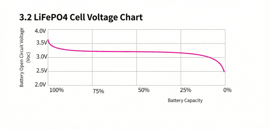
Why the LiFePO4 Flat Curve Makes Passive Balancing Particularly Problematic
LiFePO4’s discharge voltage curve is nearly flat between 20% and 90% SOC, with cell voltage varying by only 50 to 100mV across that entire range. Passive balancing is triggered by voltage differences between cells. In the flat region, a 10% SOC difference between two cells produces only 10 to 20mV of voltage difference. This is below or at the trigger threshold of most passive BMS units.
The passive Daly BMS therefore has only a narrow window of effective balancing per charge cycle: the steep region above 3.35V per cell at the very top of the LiFePO4 charge curve, where voltage differences are more pronounced. Outside this window, which represents roughly 80% of each charge cycle, the passive BMS is effectively blind to cell imbalance.
The JK BMS active balancer with a 10mV trigger threshold operates throughout the charge cycle. It does not depend on large voltage differences to detect imbalance. It acts on small imbalances early, before they compound into large ones. This is the correct engineering approach for LiFePO4 chemistry.
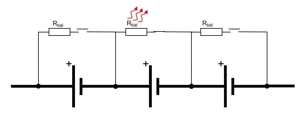
Why Passive Balancing Makes Nigerian Conditions Worse
When the Daly standard BMS passive balancing activates, bypass resistors convert cell energy into heat. This heat is generated on the BMS PCB, directly inside the battery enclosure, at the precise time when the enclosure is already at its hottest: midday charging during peak solar hours in the Nigerian dry season.
With four or more cells balancing simultaneously at 60mA each, the passive BMS is dissipating approximately 0.8 to 1.5W of heat continuously into an enclosure that may already be at 45 degC ambient. This raises the BMS PCB temperature by 3 to 8 degC, pushing thermistors and electrolytic capacitors closer to their rated maximums and accelerating PCB component aging.
The JK BMS active balancer generates minimal heat during balancing. Energy is transferred from one cell to another at 85 to 92% efficiency. The small conversion loss is approximately 0.03 to 0.06W per cell pair being balanced, which is negligible in any enclosure thermal budget. For hot-climate installations, this is a meaningful operational advantage.
Communication Capability: How Each BMS Talks to Your Inverter
Both the JK BMS and the Daly Smart BMS support RS485 communication with most major Chinese hybrid inverters. But the depth and reliability of that communication differs in ways that matter for system performance.
Communication Parameter
JK BMS
Daly BMS
RS485 availability
All active balancer variants
Smart BMS variants only; not on standard
CAN bus availability
Select variants (less common in Nigerian market)
Not available
Data transmitted: SOC
Yes; coulomb-counted, accurate
Yes (Smart BMS); coulomb-counted
Data transmitted: cell voltages
Yes; all 16 cells in real time
Yes (Smart BMS); all cells
Data transmitted: CVL
Yes; reduces as cells approach full
Yes (Smart BMS)
Data transmitted: CCL
Yes; reduces at high temp and near full
Yes (Smart BMS)
Data transmitted: DCL
Yes; reduces near empty and at high temp
Yes (Smart BMS)
Data transmitted: fault codes
Yes; specific fault flags
Yes (Smart BMS); less detailed flag set
Deye inverter compatibility
Yes; confirmed with Deye SUN-xK-SG series
Yes (Smart BMS); verify firmware version compatibility
Growatt compatibility
Yes
Yes (Smart BMS)
Victron compatibility
CAN variant only
Not available (no CAN support)
Protocol reliability
Stable; register map well-documented
Some register map changes between firmware versions; verify before deployment
Communication cable
RS485 terminal block or RJ45 depending on variant
RS485 terminal block on Smart BMS
The Dynamic Limits Difference
Both the JK BMS and Daly Smart BMS broadcast CVL, CCL, and DCL to the inverter over RS485. This is the most operationally important communication function: it allows the inverter to adapt its charging and discharging behaviour in real time to the actual state of the battery.
The practical difference emerges in two areas. First, the JK BMS register map is better documented and more stable across firmware versions. Register map changes in Daly Smart BMS firmware have caused protocol compatibility issues with specific inverter firmware versions in the field, requiring either BMS firmware rollback or inverter firmware update to restore communication. This is a real-world maintenance burden that the JK BMS has largely avoided due to more conservative firmware change management.
Second, the JK BMS CAN bus variant extends Victron compatibility. Daly has no CAN bus output. Any installation using a Victron GX device requires either the JK BMS CAN variant or a protocol converter from RS485 to VE.Can. The JK BMS CAN variant eliminates the protocol converter entirely.
Bluetooth App Comparison: What You Can See and Do Remotely
The Bluetooth app is the primary diagnostic and configuration interface for any smart BMS. The quality of the app determines how easily a field technician can identify problems, configure thresholds, and verify system health without physically disconnecting any components.
App Feature
JK BMS App
Daly BMS App (Smart variant)
Platform
iOS and Android
iOS and Android (Smart BMS only)
Individual cell voltages
Yes; real-time, all cells displayed simultaneously
Yes (Smart BMS)
Active balance indicator
Yes; shows which cells are balancing and balance current magnitude
No (passive BMS has no active balance to display)
Fault history log
Yes; timestamped with cell voltages and temperatures at each event
Limited; some Smart BMS variants store only last fault
Moderate; adequate for basic monitoring, limited for deep diagnosis
Why the Fault History Log Matters in Field Service
The most practically significant app difference is the fault history log. The JK BMS stores a timestamped log of every protection event with the cell voltages, temperatures, and current at the time of each event. When an installer receives a report that the battery keeps disconnecting, opening the JK BMS app shows exactly: which protection triggered (OVP, UVP, OCP, OTP), which cell triggered it, what time it happened, what all 16 cell voltages were at that moment, and what the temperature was.
This turns a multi-hour diagnostic exercise into a 5-minute targeted investigation. The root cause (weak cell, misconfigured inverter charge voltage, overheated enclosure) is immediately visible from the fault log data.
The Daly Smart BMS stores limited fault history. Some variants store only the most recent fault without a timestamp. Diagnosing a recurring fault on a Daly BMS requires either being present during a trip event or relying on the customer’s description of symptoms. This is a meaningful operational disadvantage for professional installers managing multiple field installations.
Protection Threshold Configurability: Why Fixed Thresholds Are a Problem
The ability to configure protection thresholds is not an optional convenience feature. For LiFePO4 installations, it is operationally necessary for two reasons.
First, the correct OVP and UVP thresholds differ by cell batch. Different LiFePO4 cell manufacturers specify slightly different safe voltage ranges. A BMS with fixed thresholds cannot be optimised for the specific cells installed. It either overprotects (tripping before the cells are damaged) or underprotects (allowing conditions that stress the cells) depending on how the factory defaults were set relative to the installed cells.
Second, the correct charge OTP threshold for Nigerian conditions is more conservative than global defaults. The correct setting is 50 degC hard cutoff, not the 55 to 65 degC factory defaults common on many BMS units. A BMS that cannot be configured to 50 degC charge OTP is providing inadequate thermal protection for Nigerian ambient conditions.
Configuration Parameter
JK BMS
Daly BMS
Overvoltage protection (OVP)
Configurable: set to 3.65V per cell for LiFePO4
Fixed on standard variants; limited on some Smart BMS variants
Undervoltage protection (UVP)
Configurable: recommend 2.80V for daily cycling LiFePO4
Fixed on standard variants; often defaults to 2.50V which is less conservative
Charge overcurrent (OCP-C)
Configurable per rated charge current
Fixed on most variants
Discharge overcurrent (OCP-D)
Configurable; set at 125% of max inverter demand
Fixed or limited on most variants
Charge OTP hard limit
Configurable: set to 50 degC for Nigerian conditions
Present but may default to 55-65 degC; verify configurability
Discharge OTP hard limit
Configurable
Present but configurability varies
Balance start threshold
Configurable: recommend 10mV for LiFePO4
Fixed on most variants; typically 20-50mV
Balance current
Configurable: 0.5A to 2A
N/A (passive; fixed at 30-60mA by resistor value)
Recovery voltage (OVP reset)
Configurable
Fixed on most variants
Recovery voltage (UVP reset)
Configurable
Fixed on most variants
CONFIGURATION IMPACT
A JK BMS with factory default thresholds is not a correctly configured JK BMS. The advantage of full configurability is only realised when the thresholds are actually set to match the installed cells and the installation environment. An unconfigured JK BMS and a configured Daly Smart BMS may perform comparably on protection. A correctly configured JK BMS outperforms both. Always configure thresholds from the app before placing a new installation in service.
The upfront cost difference between JK BMS and Daly BMS is real and meaningful. A standard Daly BMS for a 16S 100A application costs approximately 5,000 to 10,000 NGN. A JK BMS active balancer for the same configuration costs 18,000 to 30,000 NGN. The difference is 8,000 to 25,000 NGN depending on variants.
The question is not whether the JK BMS costs more. It does. The question is whether the JK BMS is worth more over the lifetime of the installation.
The Capacity Loss Calculation
A 200Ah LiFePO4 pack with a passive Daly BMS in daily cycling service at 80% depth of discharge delivers approximately 160Ah of usable capacity initially. After 18 months of progressive cell imbalance accumulation without active correction, the usable capacity typically reduces to 120 to 130Ah as the weakest cells limit the accessible range. The pack delivers 75 to 81% of its initial capacity.
The same 200Ah pack with a JK BMS active balancer maintaining cell matching within 20mV typically retains 90 to 95% of initial capacity after 18 months of the same cycling profile. The pack delivers 144 to 152Ah.
The difference is 14 to 32Ah of usable capacity per cycle. In a system with a 5kVA inverter drawing 3 to 4kWh nightly, this capacity difference translates to 30 to 75 minutes of additional runtime per night, or equivalently, a reduction in generator runtime for the same daily energy budget.
Over a 5-year installation horizon, the cumulative value of retained capacity in the JK BMS system substantially exceeds the 8,000 to 25,000 NGN initial price premium. The Daly standard BMS is not cheaper over the system lifetime. It is more expensive.
The BMS Replacement Cost
The Daly standard BMS has no fault history log and limited diagnostic capability. When it fails or causes problems, diagnosis requires either replacing the BMS speculatively or having a technician present during a fault event. For installations in remote locations or in customer premises where access requires scheduling, this diagnostic limitation adds time and cost to every service event.
The JK BMS fault log allows remote diagnosis via Bluetooth before a site visit. In many cases, the problem can be identified and resolved with a configuration change or a single targeted site visit rather than multiple diagnostic visits. For professional installers managing a portfolio of installations, this efficiency difference compounds significantly over time.
Which BMS for Which Installation
Scenario
Recommended
Rationale
48V 100Ah DIY pack, daily cycling, Deye or Growatt inverter
JK BMS
Active balancing corrects daily imbalance. RS485 provides accurate SOC and dynamic limits to inverter. Configurable thresholds allow optimisation for specific cells.
48V 200Ah DIY pack, daily cycling, Deye or Growatt inverter
JK BMS
At 200Ah, passive balancing is definitively inadequate. Only active balancing can maintain cell matching across daily deep cycling. JK BMS is the clear choice.
48V 50Ah backup UPS, cycling weekly or less
Daly standard or smart
Low cycling frequency means passive balancing keeps pace. The JK BMS cost premium is not justified for this use case.
48V 300A+ high-current industrial application
Daly (high-current variants)
Daly offers 300A, 400A, and 500A variants. JK BMS active balancer series tops out at 200A for standard configurations. Daly wins on current range at the high end.
48V Victron-based system requiring CAN communication
JK BMS (CAN variant)
Daly has no CAN support. JK BMS CAN variant is the only like-for-like active balancer option with CAN.
At 5,000 to 10,000 NGN, Daly standard delivers adequate hard fault protection for a fraction of the JK BMS cost. Not optimal, but acceptable for cost-constrained builds.
Replacement of failed Daly BMS on existing pack
JK BMS
Drop-in upgrade. Same electrical connections. Active balancing will correct accumulated imbalance from the previous passive BMS period. Configure thresholds carefully to match installed cells.
OVERALL VERDICT
For 48V LiFePO4 packs above 100Ah in daily solar cycling service in Nigeria, the JK BMS active balancer series is the correct engineering specification. The active balancing advantage is not marginal: it is the difference between a battery system that maintains its performance over 5 years and one that loses 20 to 35% of usable capacity within 18 months. The 8,000 to 25,000 NGN price premium is recovered within the first year through retained capacity and avoided service costs. The Daly BMS is not a bad product; it is a product that is correctly specified for lower-intensity applications and misspecified for daily-cycling solar storage above 100Ah.
Common Mistakes When Choosing Between JK BMS and Daly BMS
MISTAKE 1
Choosing Daly standard for a large pack because the current rating matches on paper. A 200A Daly standard BMS and a 200A JK BMS active balancer are not equivalent products for a 200Ah daily-cycling pack. The current rating match is necessary but not sufficient. The balancing capability determines whether the pack maintains performance over time. The Daly standard 200A BMS will protect the pack from hard faults; it will not prevent the progressive capacity loss from passive balancing inadequacy.
MISTAKE 2
Comparing standard Daly to active JK BMS on price without considering the Daly Smart BMS with active add-on. The correct Daly comparison for a daily-cycling large pack is: Daly Smart BMS plus active balancer add-on module versus JK BMS active balancer. When both are specced correctly, the total cost difference narrows significantly, and the JK BMS wins on integration simplicity (one unit versus two) rather than just on balancing capability.
MISTAKE 3
Purchasing JK BMS from unverified sources. The JK BMS popularity has attracted counterfeit products into the Nigerian market. A counterfeit JK BMS may look identical externally but contain passive balancing circuitry rather than the genuine active inductor-based circuit, undersized MOSFETs, and non-functional Bluetooth. Verify the QR code before purchase and test the app before installation.
MISTAKE 4
Not configuring the JK BMS thresholds after installation. A JK BMS running on factory defaults does not deliver its full potential. Configure OVP to 3.65V, UVP to 2.80V, charge OTP to 50 degC, balance start threshold to 10mV, and active balance current to 1.5 to 2A before placing the system in service. Leaving factory defaults means operating with thresholds that were set for a global average, not for Nigerian conditions and specific cell chemistry.
For the complete commissioning protocol including BMS configuration verification, our hybrid solar system commissioning checklist covers every step from physical installation through to verified system operation.
Frequently Asked Questions
Is JK BMS better than Daly BMS for solar storage?
For 48V LiFePO4 packs above 100Ah in daily solar cycling service, the JK BMS active balancer variant is the stronger engineering choice. The primary differentiator is active balancing: JK BMS integrates inductor-based active balancing at up to 2A directly on the PCB, while the standard Daly BMS uses passive balancing at 30 to 60mA only. For large daily-cycling packs, passive balancing cannot keep pace with cell divergence. JK BMS also has fully configurable protection thresholds, a more detailed Bluetooth app, and a timestamped fault history log that the standard Daly lacks. For small packs or infrequent cycling, the Daly standard BMS is a cost-effective choice where the performance difference is minimal.
Which BMS is better for a Deye inverter, JK or Daly?
Both the JK BMS RS485 variant and the Daly Smart BMS RS485 variant are compatible with Deye SUN-xK-SG inverters. The JK BMS is the stronger choice because it broadcasts the full CVL, CCL, and DCL dynamic limits in addition to SOC and cell data, allowing the Deye inverter to make more intelligent charge and discharge decisions. The Daly smart BMS also broadcasts these limits but the register map compatibility should be verified against the specific Deye firmware version installed, as Daly register maps have changed across firmware versions and compatibility gaps have been reported.
Can I replace a Daly BMS with a JK BMS?
Yes. The JK BMS is a drop-in replacement for a Daly BMS in terms of electrical connection, provided the cell count and current rating match. The communication cable must be reconnected and the inverter battery protocol setting updated from Daly to JK BMS (or equivalent). All protection thresholds should be reconfigured in the JK BMS app to match the installed cells rather than using factory defaults. After replacement, perform a full charge cycle and verify in the BMS app that all cells are being monitored and that the inverter is receiving SOC data correctly.
What is the JK BMS active balancer current and why does it matter?
The JK BMS active balancer transfers charge between cells at up to 2A, configurable down to 0.5A in the app. This matters because balancing current directly determines how quickly cell imbalance can be corrected. A 200Ah pack with a 10Ah SOC imbalance (5% divergence) requires approximately 5 hours to correct at 2A. The same imbalance would require 100 hours to correct with 100mA passive balancing. For a daily cycling solar system, only active balancing at sufficient current can correct each day’s accumulated imbalance within a single charge cycle.
Does the Daly BMS have Bluetooth?
The standard Daly BMS does not have Bluetooth. The Daly Smart BMS variant does include a Bluetooth module, allowing connection to the Daly BMS app for cell voltage monitoring, SOC display, and basic fault viewing. The smart variant also adds RS485 communication for inverter integration. If Bluetooth monitoring is required, specify the Daly Smart BMS rather than the standard Daly.
What is the Daly BMS app like compared to JK BMS?
The JK BMS Bluetooth app is generally regarded as more capable and more detailed than the Daly BMS app. The JK app displays individual cell voltages in real time, active balance current, timestamped fault history, configurable protection thresholds, and SOC calibration tools. The Daly smart app displays cell voltages, SOC, current, and basic fault status, but threshold configuration is more limited and the fault log is less detailed. For professional field diagnosis, the JK BMS app provides significantly more diagnostic value.
Which BMS has better short circuit protection, JK or Daly?
The JK BMS active balancer series uses hardware comparator-based short circuit detection with a response time under 200 microseconds. The standard Daly BMS varies by variant: premium Daly variants also use hardware comparators, but budget-tier Daly units may use firmware-based detection which is slower. For NMC or NCA chemistry, fast hardware SCP is safety-critical. For LiFePO4, the difference is less acute due to LiFePO4’s thermal stability, but hardware SCP is still preferable. Verify the specific Daly variant’s SCP response time from the datasheet before specifying for any application.
Is Daly BMS safe for LiFePO4 batteries?
Yes. Standard Daly BMS units provide adequate protection against the hard fault conditions that can damage LiFePO4 cells: overvoltage, undervoltage, overcurrent, short circuit, and overtemperature. The limitation is not safety in the acute fault sense but long-term performance: the passive balancing at 30 to 60mA is insufficient to maintain cell matching in large daily-cycling packs, leading to progressive capacity loss over 12 to 24 months. For smaller packs with less frequent cycling, the Daly BMS is safe and adequate.
Can I add active balancing to an existing Daly BMS?
Yes. External active balancer modules are available that connect to the cell tap wires of a pack with a passive BMS. These modules operate independently of the BMS and can provide 1 to 2A of active balancing to a pack that currently has only passive balancing. However, the external balancer and the Daly BMS are not coordinated: the balancer does not know the BMS’s SOC or fault state, and the two systems can occasionally work at cross-purposes. Daly also produces an official active balancer add-on module designed for use with their smart BMS that provides better coordination. The cleanest solution for a new installation is to specify a JK BMS with integrated active balancing from the start.
What is the price difference between JK BMS and Daly BMS in Nigeria?
In the Nigerian market, the standard Daly BMS (16S, 100A passive) typically costs 5,000 to 10,000 NGN. The Daly Smart BMS (16S, 100A with RS485 and Bluetooth) typically costs 10,000 to 18,000 NGN. The JK BMS active balancer (16S, 100A to 200A with active balancing, RS485, and Bluetooth) typically costs 18,000 to 40,000 NGN depending on current rating and variant. These prices fluctuate with import costs and exchange rates. The JK BMS premium over a comparable Daly smart BMS is typically 8,000 to 20,000 NGN, which represents the cost of the integrated active balancing capability.
I am Engr. Ubokobong Ekpenyong, a solar specialist and lithium battery systems engineer with over five years of hands-on experience designing, assembling, and commissioning off-grid solar and energy storage systems. My work focuses on lithium battery pack architecture, BMS configuration, and system reliability in off-grid and high-demand environments.
Contains information related to marketing campaigns of the user. These are shared with Google AdWords / Google Ads when the Google Ads and Google Analytics accounts are linked together.
90 days
__utma
ID used to identify users and sessions
2 years after last activity
__utmt
Used to monitor number of Google Analytics server requests
10 minutes
__utmb
Used to distinguish new sessions and visits. This cookie is set when the GA.js javascript library is loaded and there is no existing __utmb cookie. The cookie is updated every time data is sent to the Google Analytics server.
30 minutes after last activity
__utmc
Used only with old Urchin versions of Google Analytics and not with GA.js. Was used to distinguish between new sessions and visits at the end of a session.
End of session (browser)
__utmz
Contains information about the traffic source or campaign that directed user to the website. The cookie is set when the GA.js javascript is loaded and updated when data is sent to the Google Anaytics server
6 months after last activity
__utmv
Contains custom information set by the web developer via the _setCustomVar method in Google Analytics. This cookie is updated every time new data is sent to the Google Analytics server.
2 years after last activity
__utmx
Used to determine whether a user is included in an A / B or Multivariate test.
18 months
_ga
ID used to identify users
2 years
_gali
Used by Google Analytics to determine which links on a page are being clicked
30 seconds
_ga_
ID used to identify users
2 years
_gid
ID used to identify users for 24 hours after last activity
24 hours
_gat
Used to monitor number of Google Analytics server requests when using Google Tag Manager
1 minute
You can find more information in our Cookie Policy and .


: Honest Brand-by-Brand Comparison")


