4S, 8S, 16S LiFePO4 battery configuration: Choosing the Right LiFePO4 Battery Configuration
4S 8S 16S LiFePO4 battery configuration explained with full voltage calculations, BMS sizing, inverter compatibility, series vs parallel wiring, and 12V, 24V, 48V solar battery pack design guidance.
I get this question from installers and DIY builders regularly. Someone has 16 cells, a BMS, and an inverter, and they are not sure how to arrange the cells. Or they have purchased a BMS labelled ’48V’ and want to know how many cells go with it. Or they are comparing two pack options and one says 16S while the other says 8S2P, and they want to understand what they are actually comparing.
The S and P numbers are the foundation of every battery pack specification. Understanding them completely, with the mathematics behind each configuration, is what separates a builder who knows what they are doing from one who is hoping it works out.
This article explains every common LiFePO4 series configuration from 4S through to 32S with full calculations, works through the series and parallel combination logic, maps each configuration to the inverter class it suits, and documents the five configuration mistakes I see regularly in Nigerian solar installations.
All calculations are shown in full. No guessing.
TL;DR
What this covers: how 4S, 8S, 16S, and other LiFePO4 series configurations work, with full voltage calculations and inverter compatibility guidance. Who it is for: DIY battery builders, solar engineers, and anyone specifying a LiFePO4 pack for a specific inverter voltage. Key takeaways: – S count determines voltage. P count determines capacity. Never confuse the two. – 16S is the correct configuration for virtually every Nigerian residential and commercial solar installation. – Your inverter’s DC input voltage range is the first thing to check before choosing any configuration. – Adding cells in series raises voltage. Adding parallel strings raises capacity. Estimated read time: 14 to 18 minutes.
The Fundamental Rule: Series Adds Voltage, Parallel Adds Capacity
This rule is so important that it bears repeating before anything else.
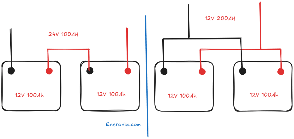
When you connect lithium cells in series, positive-to-negative in a chain, the voltages add up. If each LiFePO4 cell is 3.2V nominal and you connect 16 in series, the pack terminal voltage is 16 x 3.2V = 51.2V. The capacity (Ah) of the pack is still exactly one cell’s capacity. 16 x 200Ah cells in series does not give you 3,200Ah. It gives you 200Ah at 51.2V.
When you connect lithium cells in parallel, positive-to-positive and negative-to-negative, the capacities add up. If each cell is 200Ah and you connect two in parallel, you get 400Ah. The voltage stays at one cell’s voltage: 3.2V nominal. Two 200Ah cells in parallel at 3.2V gives you 400Ah at 3.2V. Not 6.4V.
Building a pack with the voltage and capacity you need requires combining both. A 48V 400Ah pack uses 16 cells in series (for 51.2V) and 2 cells in parallel at each position (for 400Ah). That is a 16S2P configuration: 32 cells total.
Parameter
Series Connection
Parallel Connection
What changes
Voltage increases. Capacity (Ah) stays the same as one cell.
Capacity (Ah) increases. Voltage stays the same as one cell.
What stays the same
Current capacity (Ah) of a single cell string
Voltage of a single cell string
Example
4S LiFePO4: 4 cells x 3.2V = 12.8V nominal. Each cell is still 200Ah. Pack is 200Ah at 12.8V.
2P LiFePO4: 2 cells x 200Ah = 400Ah. Each cell is still 3.2V. Pack is 400Ah at 3.2V.
Combined (16S2P)
16 cells in series gives 51.2V. 2 cells in parallel at each position gives 200Ah x 2 = 400Ah.
Pack is 51.2V nominal, 400Ah. Energy = 51.2 x 400 = 20.48 kWh gross.
BMS impact
BMS must match series count exactly. 16S BMS for 16S pack.
BMS still manages the same number of voltage nodes (series count). Current rating must cover all parallel strings combined.
When to use
When you need higher voltage for an inverter that requires it.
When you need more capacity (Ah) without changing voltage.
KEY TAKEAWAY
Series adds voltage. Parallel adds capacity. This rule never changes. If you are confused about a configuration, come back to this rule first.
Configuration Reference: Every Standard LiFePO4 Pack Voltage
LiFePO4 cells have a nominal voltage of 3.2V per cell. Maximum charge voltage is 3.65V per cell. The conservative discharge cutoff we recommend for daily cycling is 2.80V per cell. From these three numbers, every configuration’s voltage range can be calculated.
Config
What It Means
Nominal Voltage
Max Charge Voltage
Min Discharge Voltage
Inverter Class
Typical Application
4S
4 cells in series
12.8V
14.6V
10.0 to 11.2V
12V
Small UPS, lighting systems, 12V appliance circuits, portable power, small caravans
8S
8 cells in series
25.6V
29.2V
20.0 to 22.4V
24V
24V systems, medium off-grid setups, some telecoms backup applications
16S
16 cells in series
51.2V
58.4V
40.0 to 44.8V
48V
The Nigerian standard. All major hybrid inverters, large off-grid systems, commercial storage
24S
24 cells in series
76.8V
87.6V
60.0 to 67.2V
72V
Specialised high-voltage systems, some industrial UPS applications
30S
30 cells in series
96.0V
109.5V
75.0 to 84.0V
96V
High-voltage inverter systems (Deye SUN-10K-SG04LP3 and similar). Reduces DC current significantly.
32S
32 cells in series
102.4V
116.8V
80.0 to 89.6V
100V
Premium high-voltage commercial and grid-scale applications
FIELD NOTE
In the Nigerian solar market, 16S is the configuration for 99% of residential and commercial installations above 1kVA. The reasons are practical: all major hybrid inverters sold in Nigeria are designed for 48V systems, which maps directly to 16S LiFePO4. All major BMS units (JK BMS, Daly, Pylontech) have 16S variants as their primary product line. All installer training, troubleshooting guides, and supplier stock are organised around 16S. If you are building a new system and your inverter supports 48V, build 16S.
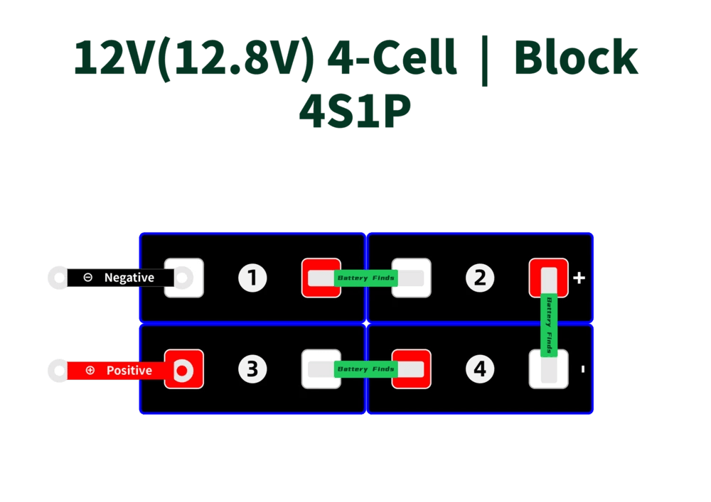
4S Configuration: 12V Systems
Four cells in series. Simple, compact, used in small 12V applications. The math is straightforward but the current numbers get high quickly at low voltage.
Parameter
4S LiFePO4 Calculation
Nominal pack voltage
4 x 3.2V = 12.8V
Maximum charge voltage
4 x 3.65V = 14.6V
Minimum discharge voltage
4 x 2.50V = 10.0V (BMS UVP; configure to 4 x 2.80V = 11.2V for conservative daily cycling)
Usable voltage window
11.2V to 14.6V (configured UVP to OVP)
Energy (100Ah cell)
100Ah x 12.8V = 1.28 kWh gross; ~1.0 kWh usable at 80% DoD
Energy (200Ah cell)
200Ah x 12.8V = 2.56 kWh gross; ~2.0 kWh usable at 80% DoD
Small cabin backup, lighting and fan circuits, 12V appliance systems
When to Use 4S
Use 4S when your load is explicitly 12V nominal: a 12V inverter, a 12V DC appliance circuit, a caravan, a boat. For anything above about 1.5kVA of inverter output, the DC current at 12V becomes very large and requires heavy copper cable throughout the system. A 2kVA inverter at 12V draws up to 182A DC. That is 60mm2 cable minimum for a 1-metre run. Managing those currents is expensive and inconvenient.
Most Nigerian solar installations that start at 12V eventually wish they had started at 48V. If you are sizing a new system, budget for 48V (16S) even if the initial load seems small. The BMS, cable, and inverter costs all scale better at 48V than at 12V as system capacity grows.
KEY TAKEAWAY
4S works for small 12V applications. Above 1.5kVA or anywhere the system might grow, 16S is the better foundation.
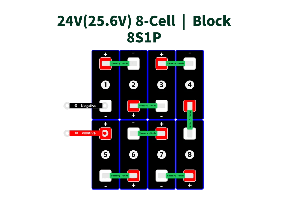
8S Configuration: 24V Systems
Eight cells in series. The 24V compromise: higher voltage than 12V reduces current by half, but still below the 48V sweet spot for most Nigerian solar applications.
Parameter
8S LiFePO4 Calculation
Nominal pack voltage
8 x 3.2V = 25.6V
Maximum charge voltage
8 x 3.65V = 29.2V
Minimum discharge voltage
8 x 2.80V = 22.4V (conservative UVP setting)
Usable voltage window
22.4V to 29.2V
Energy (100Ah cell)
100Ah x 25.6V = 2.56 kWh gross; ~2.0 kWh usable at 80% DoD
Energy (200Ah cell)
200Ah x 25.6V = 5.12 kWh gross; ~4.1 kWh usable at 80% DoD
Maximum discharge current (1C, 200Ah)
200A
BMS required
8S BMS. Most JK BMS active balancer variants cover 4S to 8S.
Typical inverter class
24V inverter/charger
Maximum inverter current (3kVA at 24V)
3,000 / 22V = 136A. Use BMS rated 170A minimum (136 x 1.25).
Common application in Nigeria
Medium off-grid systems, 24V inverter installations, some rural electrification setups
When to Use 8S
The 8S configuration is relevant when your inverter specifically requires 24V, or when you are expanding an existing 24V system that was originally built around lead-acid. For new builds, 48V (16S) is almost always a better specification unless there is a specific constraint forcing 24V.
One practical scenario where 8S makes sense: a telecommunications backup installation using a 24V inverter that is already installed and cannot be replaced. In that case, building an 8S LiFePO4 replacement for an existing lead-acid 24V battery bank is a clean upgrade that does not require changing the inverter.
A key BMS note for 8S: the JK BMS B2A8S20P covers 4S to 8S configurations. For 8S, confirm the specific variant covers exactly 8S and is not limited to 4S or 6S. Check the datasheet.
16S Configuration: 48V Systems
Sixteen cells in series. 51.2V nominal. This is the configuration for the vast majority of solar storage in Nigeria, and for good reason.
At 48V, a 5kVA inverter draws approximately 109A at maximum load. That is manageable with 50mm2 cable and a 200A BMS. The same 5kVA at 12V would draw 417A — impractical in any residential installation. At 24V, it draws 208A. Still high. At 48V (16S), the current is in a range where sensible cable and BMS sizing is straightforward and cost-effective.
Parameter
16S LiFePO4 Calculation
Nominal pack voltage
16 x 3.2V = 51.2V
Maximum charge voltage
16 x 3.65V = 58.4V
Minimum discharge voltage
16 x 2.80V = 44.8V (conservative UVP setting)
Usable voltage window
44.8V to 58.4V
Energy (100Ah cell)
100Ah x 51.2V = 5.12 kWh gross; ~4.1 kWh usable at 80% DoD
Energy (200Ah cell)
200Ah x 51.2V = 10.24 kWh gross; ~8.2 kWh usable at 80% DoD
Energy (280Ah cell)
280Ah x 51.2V = 14.34 kWh gross; ~11.5 kWh usable at 80% DoD
Maximum discharge current (1C, 200Ah)
200A
BMS required
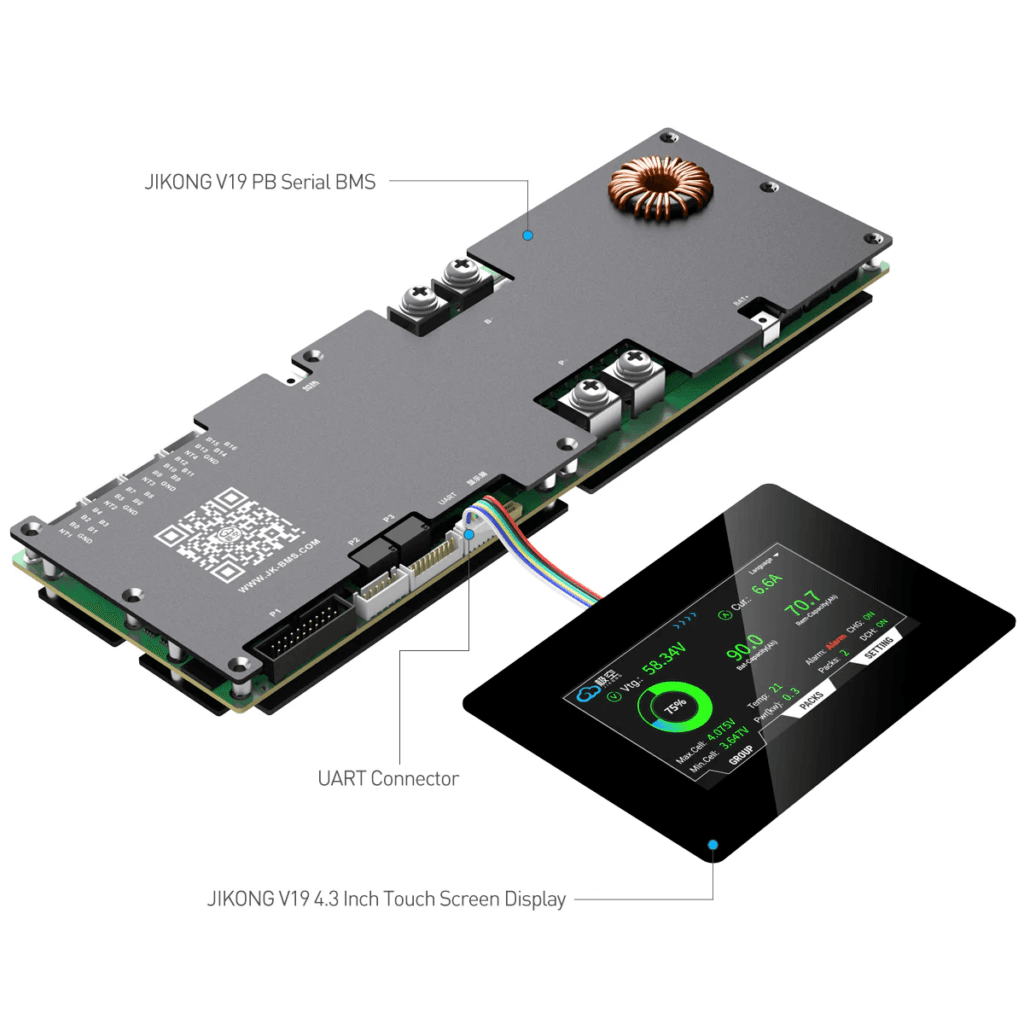
16S BMS. JK BMS B2A24S20P covers 4S to 24S, including 16S.
Typical inverter class
48V hybrid or off-grid inverter (Deye, Growatt, Victron, Solis)
Maximum inverter current (5kVA at 48V)
5,000 / 46V = 108.7A. BMS minimum: 108.7 x 1.25 x 1.15 = 156A. Use 200A BMS.
Maximum inverter current (8kVA at 48V)
8,000 / 46V = 173.9A. BMS minimum: 173.9 x 1.25 x 1.15 = 250A. Use 250A BMS.
Nigerian market availability
Dominant configuration. All major hybrid inverters sold in Nigeria support 48V. JK BMS, Daly, and Pylontech all natively support 16S.
The 16S Calculation in Detail
Let us work through a complete 16S pack calculation for a typical Nigerian installation.
Target: 48V 200Ah pack for a 5kVA Deye hybrid inverter.
Nominal voltage: 16 x 3.2V = 51.2V. This is the pack voltage at approximately 50% SOC.
Maximum charge voltage: 16 x 3.65V = 58.4V. The inverter’s charge voltage setting must be 58.4V. Confirm the Deye 5kVA accepts up to 60V (it does: rated 40 to 60V DC input). Confirmed compatible.
Minimum discharge voltage (configured in BMS as UVP): 16 x 2.80V = 44.8V. The inverter’s low battery cutoff must be set below 44.8V or the inverter will cut off before the BMS does.
Usable energy at 80% DoD: 10.24 kWh x 0.80 = 8.19 kWh.
Estimated deliverable to loads (at 90% inverter efficiency): 8.19 kWh x 0.90 = 7.37 kWh.
Maximum DC current at full load: 5,000 VA / 46V (minimum operating voltage) = 108.7A.
BMS minimum current rating: 108.7A x 1.25 (standard margin) x 1.15 (Nigerian thermal derating) = 156.3A. Use 200A BMS.
The complete BMS sizing calculation for every inverter size at 48V is covered in our article: how to size a BMS correctly.
KEY TAKEAWAY
For any 48V inverter in Nigeria: 16S is the configuration. 16 x 3.2V = 51.2V nominal. 16 x 3.65V = 58.4V maximum charge. 16 x 2.80V = 44.8V minimum discharge. Memorise these three numbers.
30S and 32S: High-Voltage Configurations
High-voltage inverters designed for 96V or 100V input require 30S or 32S LiFePO4 packs. These configurations are less common in the Nigerian residential market but are increasingly relevant as larger commercial systems are installed.
30S Calculation
30 cells in series: 30 x 3.2V = 96.0V nominal. Maximum charge: 30 x 3.65V = 109.5V. Minimum discharge (configured UVP): 30 x 2.80V = 84.0V.
The primary advantage of high-voltage systems is current reduction. A 10kVA inverter on a 48V system draws 217A at full load. The same 10kVA inverter on a 96V system draws only 104A. This halves the BMS current requirement (150A BMS instead of 250A), halves the cable cross-section requirement, and reduces busbar and terminal heating.
30S and 32S BMS units are less widely available in the Nigerian market than 16S units. JK BMS produces high-voltage variants but they are not stocked by most local distributors and require advance ordering. Daly also has 30S and 32S variants in their product range.
Before specifying a high-voltage configuration, confirm that your chosen BMS model is available at the 30S or 32S rating in the Nigerian market. Do not specify a battery configuration around a BMS that may be 6 to 8 weeks away.
Parallel Configurations: Adding Capacity Without Changing Voltage
Once the series count is fixed by the inverter voltage requirement, the only way to increase pack capacity is to add parallel strings. Each additional parallel string adds one cell’s worth of Ah at each position in the series string.
Configuration
Cell Count
Pack Voltage
Capacity
Gross Energy
Notes
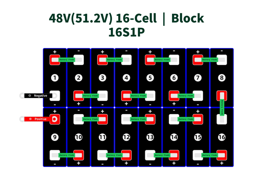
16S1P (single string)
16 cells
51.2V nominal
200Ah
10.24 kWh
1 BMS, 1 string. Simplest build. Best for first-time DIY builders.
16S2P (double string)
32 cells
51.2V nominal
400Ah
20.48 kWh
2 BMS units (one per string) or one BMS rated for 2x string current. More complex wiring. Each string balanced independently.
16S3P (triple string)
48 cells
51.2V nominal
600Ah
30.72 kWh
3 BMS units or one BMS sized for 3x string current. Parallel bus connecting all three P+ and P- terminals to inverter.
16S4P (quad string)
64 cells
51.2V nominal
800Ah
40.96 kWh
4 BMS units. Commercial-scale DIY. Requires careful parallel wiring with equal cable lengths from each string to the bus.
The BMS Question for Parallel Packs
Each parallel string should have its own BMS. This is the clean, correct engineering approach. Each BMS monitors and protects its own string of 16 cells. The P+ and P- terminals of all strings connect to a common parallel bus, which then connects to the inverter.
Using a single BMS for multiple parallel strings is possible if the BMS is rated for the combined current, but it means the cells in one string are monitored while the cells in other strings are not. This is a significant protection gap. If one unmonitored string develops a weak cell, there is nothing to detect it.
The correct approach: one BMS per string. Each BMS protects its own cells. The parallel bus at the P+ and P- level connects all strings to the inverter. Current naturally shares between strings based on their relative internal resistance and state of charge.
The wiring procedure and current sharing considerations for parallel battery packs are covered in our article: how to wire Pylontech batteries in parallel. The same principles apply to DIY parallel packs.
KEY TAKEAWAY
One BMS per parallel string, always. A parallel pack with only one BMS means unmonitored cells in every string beyond the first. That is not protection. That is a partial protection with gaps exactly where cells are most likely to diverge.
Energy Calculations for Common Configurations
The following table works through the gross energy, usable energy at 80% DoD, and estimated deliverable energy for the most common LiFePO4 pack configurations used in Nigerian solar installations.
Configuration
Gross Energy
DoD Setting
Usable Energy (kWh)
Deliverable to Loads (est.)
16S1P, 100Ah cells
51.2V x 100Ah = 5,120 Wh = 5.12 kWh
80% DoD
5.12 x 0.80 = 4.10 kWh
~3.7 kWh (accounting for inverter and cable losses at 90% efficiency)
16S1P, 200Ah cells
51.2V x 200Ah = 10,240 Wh = 10.24 kWh
80% DoD
10.24 x 0.80 = 8.19 kWh
~7.4 kWh deliverable to loads
16S1P, 280Ah cells
51.2V x 280Ah = 14,336 Wh = 14.34 kWh
80% DoD
14.34 x 0.80 = 11.47 kWh
~10.3 kWh deliverable to loads
16S2P, 200Ah cells
51.2V x 400Ah = 20,480 Wh = 20.48 kWh
80% DoD
20.48 x 0.80 = 16.38 kWh
~14.7 kWh deliverable to loads
8S1P, 200Ah cells
25.6V x 200Ah = 5,120 Wh = 5.12 kWh
80% DoD
5.12 x 0.80 = 4.10 kWh
~3.7 kWh. Same energy as 16S1P 100Ah but at half the voltage.
4S1P, 100Ah cells
12.8V x 100Ah = 1,280 Wh = 1.28 kWh
80% DoD
1.28 x 0.80 = 1.02 kWh
~0.92 kWh. Small backup system only.
The formula for gross energy is always the same:
Gross Energy (Wh) = Pack Capacity (Ah) x Nominal Voltage (V)
Usable Energy (Wh) = Gross Energy x Depth of Discharge (as a decimal)
Deliverable Energy (Wh) = Usable Energy x Inverter Efficiency (typically 0.88 to 0.95)
For a complete worked example matching battery capacity to specific daily load requirements, see our 48V lithium battery sizing guide which walks through the full load audit to battery sizing calculation.
Inverter Compatibility: Matching Your Configuration to Your Inverter
The most important external constraint on battery configuration is the inverter’s DC input voltage range. The battery configuration must produce a voltage throughout its entire operating range that stays within the inverter’s acceptable window.
For a 16S LiFePO4 pack: the voltage swings from 44.8V (at BMS UVP cutoff) to 58.4V (at full charge). The inverter must accept this entire range. If the inverter’s minimum input voltage is above 44.8V, the BMS will disconnect the pack before the inverter reaches its own low-battery cutoff, causing unexpected shutdowns.
Inverter
Battery Class
DC Input Range
Correct Config
LiFePO4 Max Charge V
16S Compatible?
Notes
Deye SUN-5K-SG03LP1
48V (Low Voltage)
40 to 60V
16S LiFePO4
58.4V at full charge
Yes
The most common 5kVA hybrid inverter in the Nigerian market. 16S is the native configuration.
Deye SUN-10K-SG04LP3
High Voltage
80 to 120V
30S LiFePO4
109.5V at full charge
No
High voltage model requires 30S, not 16S. 16S pack voltage is below the minimum input range.
Growatt SPH5000TL
48V (Low Voltage)
40 to 60V
16S LiFePO4
58.4V at full charge
Yes
Standard 48V Growatt SPH series. 16S confirmed compatible.
Growatt SPF 5000ES
48V (Low Voltage)
40 to 60V
16S LiFePO4
58.4V at full charge
Yes
Off-grid SPF series. 16S standard.
Victron MultiPlus-II 48/5000
48V
38 to 62V
16S LiFePO4
58.4V at full charge
Yes
Victron accepts 16S. Configure absorption at 58.4V, float at 53.6V in VEConfigure.
Solis RHI-3.6K-48ES
48V
40 to 60V
16S LiFePO4
58.4V at full charge
Yes
Standard 48V Solis hybrid. 16S compatible.
Generic 12V inverter
12V
10.5 to 15V
4S LiFePO4
14.6V at full charge
Yes
Small systems only. Most Nigerian residential solar does not use 12V inverters above 1kVA.
CRITICAL CHECK
Before finalising any battery configuration, find your inverter’s datasheet and locate the DC input voltage range specification. The battery configuration must produce a maximum charge voltage at or below the inverter’s maximum DC input. The battery configuration must produce a minimum operating voltage (at BMS UVP cutoff) at or above the inverter’s minimum DC input. If either bound is violated, the system will either not charge fully or disconnect before the battery is empty.
Five Configuration Mistakes That Cause Real Problems
Every mistake in this table has been observed in Nigerian solar installations. None are hypothetical.
Mistake
Consequence
Correct Approach
Using a 16S BMS on a high-voltage inverter that requires 30S
The BMS reports 51.2V to the inverter. The high-voltage inverter expects 96 to 120V. The inverter either refuses to charge (voltage too low for its input range) or operates in a degraded mode.
Check your inverter’s DC input voltage range before specifying any battery configuration. Match the cell count to the inverter’s requirements.
Using a 16S pack with an inverter configured for lead-acid 48V charging
Lead-acid 48V systems often charge to 56 to 57.6V. The LiFePO4 16S pack charges to 58.4V. If the inverter is on lead-acid settings, it undercharges the pack by 0.8 to 1.8V, leaving the pack chronically at 90 to 95% of full charge. Over time this reduces accessible capacity.
Set the inverter battery type to Lithium or to the specific BMS brand. Configure charge voltage at 58.4V for 16S LiFePO4.
Confusing S rating with cell count when ordering a BMS
A builder with a 16S pack orders a BMS described as ’48V BMS’ without confirming the S rating. Some suppliers list an 8S BMS as a ’24V BMS’ which can be used in a 16S pack if misread. The 8S BMS monitors only 8 cells and leaves 8 unmonitored.
Always confirm the BMS S rating explicitly. A 16S pack needs a 16S BMS. Not a ’48V BMS’. Not a ‘big BMS’. 16S.
Adding cells in series to increase capacity instead of voltage
Capacity (Ah) is determined by parallel strings, not series count. Adding more cells in series only raises voltage. A 20S LiFePO4 pack has 64V nominal and the same Ah as a single cell, not more. The builder ends up with a pack that is incompatible with their 48V inverter.
Series adds voltage. Parallel adds capacity. Always. If you need more Ah at 48V, add a parallel string, not more series cells.
Not recalculating BMS current rating when moving from 1P to 2P
A 16S1P pack with a 150A BMS is correctly sized for a 5kVA inverter. If the builder adds a second parallel string to make it 16S2P without changing the BMS, the single BMS now handles 2x the current when both strings charge and discharge together. A 150A BMS on a 16S2P system sees up to 200A under full load.
Each parallel string should have its own BMS. Size each BMS for its individual string current share. Do not use one undersized BMS for a multi-parallel system.
For the broader catalogue of DIY battery build mistakes and their consequences, see our Phase 3 Article 1: how to build a LiFePO4 battery pack step-by-step. The configuration section there complements the calculations in this article.
Quick Reference: The Three Numbers Every 16S Builder Needs
If you remember nothing else from this article, remember these three numbers for a 16S LiFePO4 pack:
Parameter
Calculation
Result
What Sets It In the Inverter
Nominal voltage
16 x 3.2V
51.2V
Battery voltage display reference
Maximum charge voltage
16 x 3.65V
58.4V
Inverter absorption/charge voltage setting
BMS UVP cutoff voltage
16 x 2.80V
44.8V
Inverter low battery cutoff voltage (set slightly below this)
Set the inverter charge voltage to 58.4V. Set the inverter low battery cutoff to 44.0 to 44.5V. Configure the BMS OVP at 3.65V per cell and UVP at 2.80V per cell. Everything else follows from these settings.
Frequently Asked Questions
What does 16S mean in a LiFePO4 battery?
16S means 16 cells connected in series. In a LiFePO4 pack, each cell has a nominal voltage of 3.2V. 16 cells in series produce 16 x 3.2V = 51.2V nominal pack voltage. The S number always indicates the series cell count. A 16S BMS is required to monitor all 16 cells individually. 16S is the standard configuration for 48V nominal LiFePO4 battery packs used with nearly all hybrid and off-grid inverters sold in the Nigerian market.
What is the difference between 4S, 8S, and 16S LiFePO4?
The difference is the number of cells in series, which determines the pack voltage. 4S: 4 cells in series = 12.8V nominal. Used with 12V inverter systems. 8S: 8 cells in series = 25.6V nominal. Used with 24V inverter systems. 16S: 16 cells in series = 51.2V nominal. Used with 48V inverter systems. The capacity (Ah) of each configuration is determined by the cells themselves, not the series count. Adding cells in series never increases capacity. It only increases voltage.
How do I calculate LiFePO4 battery pack voltage?
Multiply the number of cells in series by the cell voltage for the state you want to calculate. For nominal voltage: S count x 3.2V per cell. For maximum charge voltage: S count x 3.65V per cell. For minimum discharge voltage (BMS UVP setting): S count x 2.80V per cell (conservative) or S count x 2.50V (absolute minimum). Example for 16S: Nominal = 16 x 3.2 = 51.2V. Maximum charge = 16 x 3.65 = 58.4V. Conservative UVP = 16 x 2.80 = 44.8V.
Can I use a 16S LiFePO4 battery with any inverter?
No. The inverter must be designed for 48V nominal battery systems with a DC input range that covers the LiFePO4 16S voltage swing of 44.8V to 58.4V. Most 48V hybrid inverters (Deye, Growatt, Solis, Victron MultiPlus 48V) accept this range. High-voltage inverters designed for 96V or 100V systems (such as the Deye SUN-10K-SG04LP3) require 30S LiFePO4 packs, not 16S. Always check the inverter’s DC input voltage range specification before specifying the battery configuration.
How many cells do I need for a 48V 100Ah LiFePO4 battery?
You need 16 cells in series, each rated at 100Ah. 16 cells x 3.2V nominal = 51.2V nominal (48V class). Each cell provides 100Ah of capacity. The pack total is 100Ah at 51.2V = 5.12 kWh gross energy. At 80% depth of discharge, usable energy is approximately 4.1 kWh. If you want more capacity at the same 48V voltage, add a second parallel string of 16 x 100Ah cells to get 200Ah (16S2P configuration).
What is the difference between 16S1P and 16S2P?
16S1P means 16 cells in series, 1 parallel string. Pack voltage is 51.2V nominal, capacity equals one cell’s Ah rating. 16S2P means 16 cells in series with 2 cells in parallel at each position (32 cells total). Pack voltage is still 51.2V nominal, but capacity doubles because each position has 2 cells contributing their Ah in parallel. A 16S2P pack using 200Ah cells has 400Ah total capacity and 20.48 kWh gross energy. The BMS for a 16S2P pack must handle twice the current compared to a 16S1P pack of the same cell size.
What happens if I use the wrong S rating BMS for my pack?
If the BMS has fewer S channels than the pack has series cells, some cells are left unmonitored. The BMS cannot detect overvoltage, undervoltage, or imbalance on those unmonitored cells. Those cells can be overcharged, deep-discharged, or diverge from the rest of the pack without any protection activating. This causes accelerated cell degradation and in NMC or NCA chemistries can create safety hazards. Always match the BMS S rating exactly to the number of series cells in the pack.
How do I connect two 16S1P packs in parallel?
Connect the positive terminals of both packs together on a shared positive busbar. Connect the negative terminals of both packs together on a shared negative busbar. The shared busbars connect to the inverter. Each pack must have its own BMS. The two packs should be at the same state of charge before connecting them in parallel (within 0.2V of each other at the pack level) to avoid large equalisation current surges when they are first joined. Use equal cable lengths from each pack to the parallel bus to encourage equal current sharing.
I am Engr. Ubokobong Ekpenyong, a solar specialist and lithium battery systems engineer with over five years of hands-on experience designing, assembling, and commissioning off-grid solar and energy storage systems. My work focuses on lithium battery pack architecture, BMS configuration, and system reliability in off-grid and high-demand environments.
Contains information related to marketing campaigns of the user. These are shared with Google AdWords / Google Ads when the Google Ads and Google Analytics accounts are linked together.
90 days
__utma
ID used to identify users and sessions
2 years after last activity
__utmt
Used to monitor number of Google Analytics server requests
10 minutes
__utmb
Used to distinguish new sessions and visits. This cookie is set when the GA.js javascript library is loaded and there is no existing __utmb cookie. The cookie is updated every time data is sent to the Google Analytics server.
30 minutes after last activity
__utmc
Used only with old Urchin versions of Google Analytics and not with GA.js. Was used to distinguish between new sessions and visits at the end of a session.
End of session (browser)
__utmz
Contains information about the traffic source or campaign that directed user to the website. The cookie is set when the GA.js javascript is loaded and updated when data is sent to the Google Anaytics server
6 months after last activity
__utmv
Contains custom information set by the web developer via the _setCustomVar method in Google Analytics. This cookie is updated every time new data is sent to the Google Analytics server.
2 years after last activity
__utmx
Used to determine whether a user is included in an A / B or Multivariate test.
18 months
_ga
ID used to identify users
2 years
_gali
Used by Google Analytics to determine which links on a page are being clicked
30 seconds
_ga_
ID used to identify users
2 years
_gid
ID used to identify users for 24 hours after last activity
24 hours
_gat
Used to monitor number of Google Analytics server requests when using Google Tag Manager
1 minute
You can find more information in our Cookie Policy and .


")


