Battery String Imbalance
If you have two battery packs in parallel, current should split evenly between them. At commissioning, that is usually what happens. Both packs pull their weight, the system runs clean, and the customer is happy.
Six months later, you are back on site.
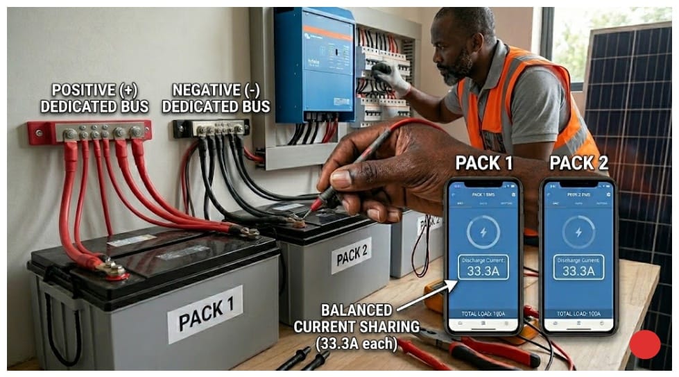
Runtime has dropped. The customer noticed it first. The system that used to run through the night is cutting out by 3am. You pull up both BMS apps. Pack 1 is showing 68A discharge. Pack 2 is showing 32A. Total load on the inverter is 100A. Pack 1 is carrying 36% more than its designed share.
That gap matters more than it looks. Pack 1 is cycling harder every single day. Deeper discharges, harder charge cycles, more heat. Pack 2 is barely breaking a sweat by comparison. At that rate, Pack 1 will need servicing 18 months before Pack 2 does. The customer paid for two identical packs expecting them to last the same time. That is not what they are getting.
This is string imbalance. It is one of the more predictable problems in multi-pack systems, not because it always shows up the same way, but because the conditions that produce it are almost always present from day one. A small difference at commissioning. Months of cycling. Then one day the numbers stop making sense.
It is also one of the most mishandled faults I have come across. The default response from many installers is to replace cells or blame the batteries. I have seen packs pulled off the wall when the actual problem was a loose terminal on a busbar. I have seen batteries returned to suppliers when the fix was re-routing a cable. Most of the time the batteries are fine. What is broken is something in how the system was built or how it has aged since. A cable problem, a configuration error, a resistance mismatch that was invisible at commissioning and only showed up once the system had some cycles on it.
This article walks through every root cause I have come across, how to test for each one on a live system, and what to actually do about it.
Why Parallel Strings Diverge:
LiFePO4 packs connected in parallel share the same positive bus and the same negative bus. Voltage equalizes across both. So by right, state of charge should track the same way across both packs.
But here is the thing. Every physical path in that system has resistance. Your cables have resistance. Your terminals have resistance. Your busbars have resistance. And none of those values are perfectly equal, and none of them stay the same as the system ages. Where you have different resistance, you get different current. Where you have different current, one pack is working harder than the other.
That harder work shows up as deeper discharge cycles, more heat per cycle, and faster cell degradation. A small difference at commissioning does not stay small. It feeds on itself every cycle until six months later you are standing on site looking at a BMS screen wondering why one pack is doing almost twice the work.
Now I want to be honest about something here. The relationship between resistance difference and current split is not always clean. Sometimes a 15% cable length difference produces a 30% current split. Sometimes it produces less. Other variables are in play, including connection quality, temperature, and how the BMS on each pack is managing current limits. The physics points you in the right direction but the numbers on site will not always match the calculation exactly. That is normal. Use the calculation to identify the likely cause, then use measurement to confirm it.
This same problem happens inside a single pack too, at the cell level. We covered that in detail in our article on why lithium batteries go out of balance. In a multi-pack system you are dealing with both at the same time. Cells drifting inside each pack, and packs drifting against each other. Same root cause, just running at two levels.
The Five Root Causes of String Imbalance
In every multi-pack installation I have looked at where string imbalance was the problem, it always traced back to one of five things. I say always but let me qualify that. Sometimes two causes are running at the same time, and that is where diagnosis gets harder. A cable resistance problem and a capacity mismatch can exist in the same system, and fixing only one will not fully resolve the imbalance. Keep that in mind as you work through the diagnostics.
Each cause shows up differently in the data, which means you can usually identify which one you are dealing with before you touch a single cable. Usually.
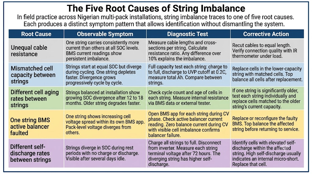
Cause 1: Unequal cable resistance
One string carries consistently more current than the other at all states of charge. The BMS current readings show persistent imbalance regardless of where the packs are in their cycle. Diagnostic: Measure cable lengths and cross-sections per string. Any length or cross-section difference over 10% is enough to explain the imbalance. Fix: Recut cables to equal length. Verify connection quality under load.
Cause 2: Mismatched cell capacity between strings
Strings start at equal SOC but diverge during cycling. One string depletes faster. The divergence grows progressively with each cycle. Diagnostic: Full capacity test each string. Charge to full, discharge to UVP cutoff at 0.2C, measure total Ah delivered. Compare between strings. Fix: Replace cells in the lower capacity string with matched cells. Top balance all cells after replacement.
Cause 3: Different cell aging rates between strings
Strings that were balanced at installation show growing SOC divergence after 12 to 18 months. The older string degrades faster. Diagnostic: Check cycle count and age of cells in each string. Measure internal resistance via BMS data or an external tester. Fix: If one string is significantly older, test each string individually and replace cells matched to the older string’s current capacity, not its original rated capacity.
Cause 4: Active balancer fault in one string
One string shows increasing cell voltage spread within its own BMS app. Pack level voltage diverges from the other string even though cables are equal. Diagnostic: Open the BMS app for each string during the CV charge phase. Check the active balancer current reading. Zero balance current during CV with visible cell spread confirms balancer failure. Fix: Replace or reconfigure the faulty BMS. Top balance the affected string before returning to service.
Cause 5: Different self-discharge rates between strings
Strings diverge in SOC during rest periods with no charge or discharge activity. The divergence is visible after several days of idle. Diagnostic: Charge all strings to full. Disconnect from the inverter. Measure each string terminal voltage after 72 hours. The diverging string has elevated self-discharge. Fix: Identify the specific cell with elevated self-discharge within the affected string. Elevated self-discharge almost always means an internal micro-short. Replace that cell.
Before you touch anything, look at the symptom pattern first. If current is splitting unevenly at every state of charge, not just at the top or the bottom of the cycle, start with cable resistance. If the packs commissioned fine but SOC has been drifting further apart month by month, you are looking at a capacity mismatch or an aging difference. If the divergence only appears when the system is sitting idle, that points to self-discharge. These patterns are not always clean in practice. Sometimes you will see overlap between two causes. But the pattern still tells you where to start.
Root Cause 1: Unequal Cable Resistance
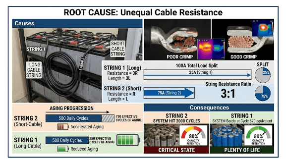
This is the most common cause of string imbalance I see in Nigerian installations, and when you catch it early it is also the easiest to fix.
It usually comes down to one of three things. Someone cut one cable slightly shorter than the other. A different cable cross-section was used on one string. Or one lug was poorly crimped and the connection is carrying extra resistance that was not there at commissioning.
The physics is straightforward. Current splits between parallel paths based on resistance. The lower the resistance, the more current that path pulls. So if one cable is 50% longer than the other, it has 50% more resistance and it will carry proportionally less current. The shorter string picks up the slack. At 100A total load with a 3:1 resistance ratio, you end up with one string carrying 75A and the other carrying 25A.
Now run that forward. Over 500 daily cycles at that split, the string carrying 75A has effectively received 750 cycles worth of aging. The other string has only seen 250. If the packs were designed for 3,000 cycle life, the overloaded string hits 80% capacity retention around cycle 2,000. The other string is sitting at cycle 670. The customer has one pack that needs replacing and one that still has years left. That is not a battery problem. That is a cable problem.
The full cable resistance calculation and equal length requirement are covered in our article on busbar sizing, cable sizing, and fuse selection for LiFePO4 battery packs. Any time you are diagnosing current imbalance in a multi-pack system, that calculation is the first thing to run.
How to Diagnose Cable Resistance Imbalance
The most reliable way to confirm this is with a milliohm meter. Measure each cable path from the pack positive terminal to the bus positive terminal, then repeat on the negative side. Equal cables of equal cross-section should read within 10% of each other. Anything beyond that and you have found your problem.
If you do not have a milliohm meter on site, you can still get a good indication. Physically measure the cables. If one run is visibly longer than the other, that is likely your culprit. Check that both cables are the same cross-section while you are at it. A 16mm² cable on one string and a 25mm² cable on the other will produce exactly this kind of imbalance and it gets missed more often than it should.
You can also use a regular multimeter under full load. Put your probes across each cable while the system is discharging and compare the voltage drop. The cable with higher resistance will show a larger drop. It is not as precise as a milliohm measurement but it will tell you which side the problem is on. One thing to keep in mind: terminal oxidation can add resistance that is not obvious from looking at the connection. If the cables measure equal but current is still splitting unevenly, check the terminal contact surfaces before assuming the cables are not the issue.
Root Cause 2: Mismatched Cell Capacity Between Strings
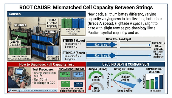
When you add a new pack to an existing installation, be careful. The pack you are adding and the pack already running are not the same anymore. One has been cycling for months. Its effective capacity has dropped. The new one is fresh off the shelf. Even if they are the same model from the same manufacturer, they are no longer equal.
A 200Ah new pack and a 188Ah aged pack will not share current equally no matter how good your cables are. The lower capacity pack fills up faster and empties faster, so it cycles deeper. Deeper cycling ages it faster. The gap keeps growing.
Even two brand new packs can have this problem. Grade A cells vary within specification. A few percent difference between two packs is enough to start the imbalance. You will not always see it immediately. Sometimes it takes three or four months before the divergence is visible in the BMS data. That does not mean it was not there from day one.
We covered how to avoid this in our article on most common DIY lithium battery mistakes that kill packs. Mistakes 1 and 2 feed directly into this root cause.
How to Diagnose Cell Capacity Mismatch
A full capacity test is the only way to confirm this definitively. Disconnect each string from the bus. Charge each individually to full at CV until current drops below 0.5C. Rest for 30 minutes. Discharge each at 0.2C to UVP cutoff. Measure the total Ah delivered from each string. A significant difference confirms capacity mismatch.
I say significant because a 2 to 3% difference between strings is not unusual and will not necessarily cause problems on its own. What you are looking for is a difference of 8% or more. That is the range where the cycling depth gap becomes large enough to accelerate aging noticeably.
Root Cause 3: Different Aging Rates Between Strings
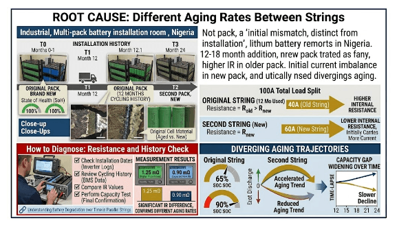
This one is different from capacity mismatch at installation. This is two strings that started equal but aged at different rates over time. The most common scenario here in Nigeria is a second pack added 12 to 18 months after the original.
The original pack has cycling history. Its cells have slightly higher internal resistance. When the new pack is connected in parallel, its lower internal resistance means it initially pulls more current. Over time the two packs diverge in aging because they started at different points in their life cycle.
Here is where it gets complicated. The newer pack aging faster early on can sometimes cause the two packs to meet somewhere in the middle and partially self-correct. I have seen this once. It is not something to count on, but it is worth knowing that the trajectory is not always a straight line divergence. Monitor the data before drawing conclusions.
When expanding an existing battery bank, run a full capacity test on the original string first. If it tests at 92% of original capacity, specify the new string with cells that test at 90 to 94% of rated. The cost difference is small. Starting with a 10% capacity mismatch compounds from day one.
Root Cause 4: Faulty Active Balancer in One String
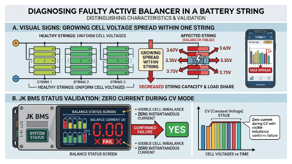
The BMS active balancer in one string stops working. Cells within that string begin diverging without correction. As the cell voltage spread grows, that string’s effective capacity decreases and it starts carrying less load than before, even if the cables are perfectly equal.
The thing that distinguishes this from cable resistance imbalance is where the divergence appears. With cable resistance, the packs diverge at the pack level but cells within each pack stay relatively balanced. With a balancer fault, the cells within the affected pack start spreading apart. The BMS app for that string will show it clearly if you know what to look for.
Diagnosing whether a JK BMS active balancer has failed is covered in our article on signs of a failing BMS. The active balancer status screen shows instantaneous balance current. Zero current during CV phase with visible cell spread confirms balancer failure. That said, some BMS units only activate the balancer above a certain cell voltage threshold, so confirm the pack was actually in CV phase before concluding the balancer has failed.
Root Cause 5: Elevated Self-Discharge in One String
A cell with an internal micro-short discharges itself faster than the cells around it. We are talking potentially 10 to 50 times the normal self-discharge rate. When that cell is sitting inside a series string in a parallel bank, it slowly drains its entire string during rest periods. After 72 hours of idle time, the affected string will be at noticeably lower SOC than the other string.
Over months this out-of-phase cycling accumulates. The affected string stresses the micro-short cell further with each cycle, which accelerates its degradation until eventually the cell fails completely.
The tricky part with this root cause is that during active cycling the imbalance can look similar to a capacity mismatch. The clearest way to separate the two is the 72-hour rest test. Capacity mismatch shows up during cycling. Self-discharge shows up during rest. If you see divergence in both conditions you may be dealing with both problems at the same time.
How Imbalance Progresses Over Time
This is where I want to be direct about what the timeline means in practice, because the numbers below are typical ranges, not fixed rules. A system running high daily loads will move through these stages faster. A system with light loads and shallow cycles may take longer to show symptoms. Use this as a guide, not a strict schedule.
0 to 3 months
SOC divergence is typically under 5%. Voltage difference between string terminals at rest is under 0.05V. Nothing visible yet. This is the window to verify your commissioning baseline and confirm current sharing is equal.
3 to 6 months
SOC divergence of 5 to 10%. Voltage difference of 0.05 to 0.1V at rest. Worth opening the BMS apps and having a look. Not urgent but this is the easiest time to catch a cable problem before it does any cell damage.
6 to 12 months
SOC divergence of 10 to 20%. Voltage difference of 0.1 to 0.2V. One BMS may be showing consistently higher current than the other. Investigation is needed at this stage. Cable imbalance or cell aging divergence are the likely causes.
12 to 18 months
SOC divergence of 20 to 35%. Voltage difference of 0.2 to 0.4V. One string is being stressed while the other is underloaded. Corrective action is required. The longer you leave it at this stage the more cell damage accumulates.
18 months and beyond
SOC divergence over 35%. Voltage difference over 0.4V. One BMS may be tripping overcurrent protection while the other shows normal load. This is urgent. At least one pack has degraded and a capacity test is the next step before anything else.
The 3 to 6 month window is the one that matters most. Problems caught before the 6-month mark can almost always be resolved without touching a single cell. After 12 months of imbalanced operation, you are likely looking at cell replacement even after the root cause is fixed.d.
Correcting String Imbalance:
1. Cable resistance imbalance (under 3 months)
Disconnect the affected string from the bus. Recut the cables to equal length and equal cross-section. Reconnect and verify that current sharing is within 15% under load. If you caught it at this stage, no cell damage is expected.
2. SOC divergence from unequal current sharing (3 to 12 months)
Fix the cable resistance first. Then charge each string individually to full before reconnecting to the bus. Run 3 to 5 full cycles while watching the BMS current readings per string. If cell capacity is still matched between the packs, SOC should converge within those 5 cycles.
3. Cell capacity divergence between strings (12 to 18 months)
Run a full capacity test on all strings. If one string tests below 85% of the other at the same age, cell degradation has already happened. Replace the degraded cells with matched cells, top balance everything after replacement, and verify equal capacity before reconnecting to the bus.
4. Active balancer fault in one string
Pull up the BMS app and diagnose the specific fault. If the balancer circuit has failed, replace the BMS. If it is a configuration issue, reconfigure through the Bluetooth app. Top balance the affected string before returning it to service.
5. Self-discharge divergence
Let the system rest for 72 hours, then test individual cell voltages. The cell with elevated self-discharge will show a lower resting voltage than the others. Replace that cell. An internal micro-short will not heal on its own.
After any correction involving disconnecting and reconnecting strings, follow the voltage matching procedure before reconnection to prevent large equalisation current events. The safe voltage matching ranges are in our article on how to connect multiple battery packs in parallel.
Prevention Is Easier Than Correction
It is easier to prevent string imbalance than to correct it. Every fix above means taking the system offline, disconnecting strings, testing cells, sometimes replacing them. The customer loses power, you spend hours on a site visit, and all of it could have been avoided.
Here is the maintenance schedule that prevents it.
At commissioning Verify equal cable lengths before you connect anything. The moment you energize the system, measure current sharing under load and write down the numbers. That baseline is what you compare everything against going forward.
At 1 month Check current sharing again. If anything has shifted from your commissioning baseline, investigate it now before it has time to compound.
At 6 months Check current sharing, cell voltage spread within each string from the BMS apps, and resting voltage difference between strings after 4 hours of rest.
Annually Run a full capacity test on each string and compare. Catching a 5% capacity divergence in year 2 is a quick fix. Catching a 25% divergence in year 3 is a cell replacement job.
The full annual health check protocol is in our article on most common DIY lithium battery mistakes that kill packs. It covers single pack systems but scales directly to multi-pack setups.
One last thing. Write the baseline current sharing values on a label and stick it inside the battery enclosure before you leave the site. Not in a spreadsheet somewhere. Not in a WhatsApp message. Inside the enclosure where the next person who opens it will see it. A system that has maintained equal current sharing for 24 months has been managed correctly. A system where nobody checked for 18 months has a surprise waiting.
Frequently Asked Questions
Why do parallel battery strings become unbalanced over time?
There are five main causes: unequal cable resistance, mismatched cell capacity between strings, different cell aging rates when strings were installed at different times, a faulty active balancer in one string, and elevated self-discharge in one string. In Nigerian installations the most common one I see is unequal cable lengths. But honestly, by the time a customer calls with a complaint, there is sometimes more than one cause running at the same time. That is why you diagnose before you fix.
How do I know if my parallel battery strings are unbalanced?
Open all BMS apps simultaneously under load and compare current readings. Balanced strings should be within 10 to 15% of each other. Also check resting voltage difference after 4 hours at the same SOC. Balanced strings should be within 50mV of each other. A large discrepancy in either one is your signal to investigate further.
Can I fix battery string imbalance without replacing cells?
Yes, if the root cause is cable resistance or SOC drift caught within 6 months. Fix the cables, charge each string individually to full, reconnect, and run 3 to 5 full cycles while watching the BMS readings. If the strings converge, no cell replacement is needed. If they keep diverging after the cable fix, run a capacity test before deciding what to do next.
How often should I check parallel battery strings for imbalance?
At commissioning, at 1 month, at 6 months, and annually after that. Any time a customer reports reduced runtime, unexpected BMS trips, or the generator running earlier than usual, check string imbalance first. It is one of the most common root causes of those complaints.
What is the maximum acceptable current imbalance between parallel strings?
Within 10 to 15% of the equal share value. For a two-string system at 100A total, each string should carry 50A plus or minus 5 to 7.5A. Above 20% consistently means something needs attention. Above 35% means one string is being damaged with every cycle and corrective action should not wait.

I am Engr. Ubokobong Ekpenyong, a solar specialist and lithium battery systems engineer with over five years of hands-on experience designing, assembling, and commissioning off-grid solar and energy storage systems. My work focuses on lithium battery pack architecture, BMS configuration, and system reliability in off-grid and high-demand environments.