Master-Slave BMS Architecture
When you connect two or more battery packs in parallel on a single inverter, a question comes up that most installation guides conveniently skip: which BMS talks to the inverter, what does it actually report about the packs it isn’t directly measuring, and what happens to the whole system when that one BMS has a problem?
The answer depends on which multi-pack communication architecture you’re running. In the Nigerian solar market, most installers are working with one of two: Pylontech’s built-in master-slave architecture, or the simpler single-master setup people use when wiring multiple JK BMS units to a Deye, Growatt, or Solis inverter.
These are not the same thing. Pylontech’s master genuinely pulls data from every unit in the bank and hands the inverter a unified picture. A JK BMS master reports its own pack only the inverter has zero knowledge of the other packs. That difference matters when you’re commissioning, when something goes wrong, and when you’re planning what to do at 2am when a BMS trips.
This article covers both architectures at the engineering level.
Why Only One BMS Can Talk to the Inverter at a Time
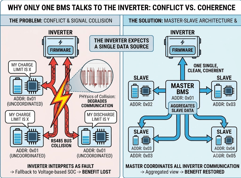
Every inverter that supports BMS communication is designed around a single data source. It polls one RS485 address, listens on one VE.Can device ID, and uses whatever comes back to make all its charge and discharge decisions. The firmware isn’t built to receive conflicting current limits from two sources at once and figure out which one to believe.
Put two BMS units on the same RS485 bus without address coordination and their signals collide. The inverter gets corrupted data, calls it a communication fault, falls back to guessing SOC from voltage, and everything you gained from BMS communication is gone.
The physics of RS485 bus collision and why it degrades communication is explained in our article on UART vs CAN vs RS485: how lithium batteries communicate with inverters. The multi-drop RS485 topology section specifically addresses why address assignment is not optional in a multi-device RS485 system.
The solution to this constraint is master-slave architecture: one unit coordinates all communication with the inverter, all other units provide data to the master or operate independently. The master presents a single, coherent view of the battery bank to the inverter, regardless of how many physical packs exist behind it.
Three Multi-Pack BMS Architectures Used in Nigerian Solar Systems
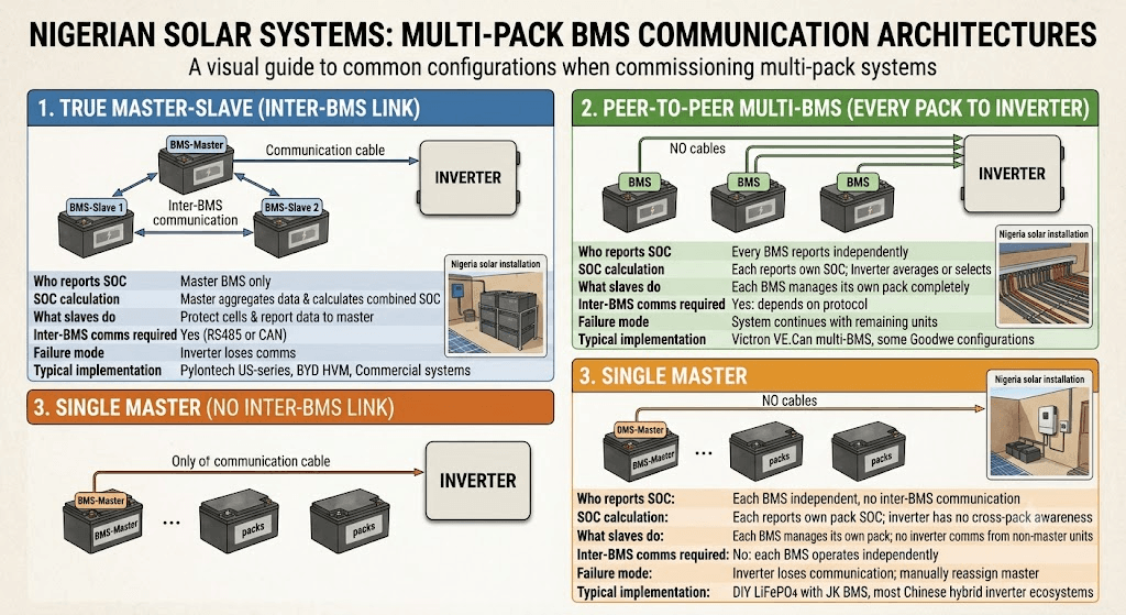
There are three distinct communication architectures you will encounter when commissioning multi-pack systems in Nigeria. They look superficially similar from the outside but function very differently.
| Parameter | True Master-Slave | Peer-to-Peer Multi-BMS | Single Master (No Inter-BMS Link) |
| Who reports SOC to inverter | Master BMS only | Every BMS reports independently | Each BMS independent, no inter-BMS communication |
| How SOC is calculated | Master aggregates data from all slaves then calculates combined SOC | Each BMS reports its own SOC; inverter averages or selects | Each BMS reports its own pack SOC; inverter has no cross-pack awareness |
| What slaves do | Protect their own cells; report cell data to master via inter-BMS communication | Each BMS manages its own pack completely | Each BMS manages its own pack; no inverter communication from non-master units |
| Inter-BMS communication required | Yes: RS485 or CAN between BMS units | Yes: depends on protocol | No: each BMS operates independently |
| Inverter communication cables | One cable: master to inverter | Multiple cables: one per BMS to inverter | One cable: one designated BMS to inverter |
| Failure mode if master fails | Inverter loses BMS communication; may revert to voltage SOC estimation | System continues with remaining units | Inverter loses communication; manually reassign master |
| Typical implementation | Pylontech US-series, BYD HVM, commercial battery systems | Victron VE.Can multi-BMS, some Goodwe configurations | DIY LiFePO4 with JK BMS, most Chinese hybrid inverter ecosystems |
The distinction that matters most in practice is whether there is communication between BMS units themselves (inter-BMS communication) or just from one designated BMS to the inverter. True master-slave systems with inter-BMS links give the master real-time data from all packs to aggregate. Single-master systems with no inter-BMS link give the inverter only the master pack’s data, with the assumption that current sharing is equal enough that the master’s data approximates the full bank state.
KEY TAKEAWAY
The practical dividing line is whether BMS units talk to each other or not. Pylontech’s master has live data from every pack because the units communicate between themselves. A JK BMS master has data from its own pack only and the inverter trusts that number to represent the whole bank.
What the Master BMS Reports to the Inverter
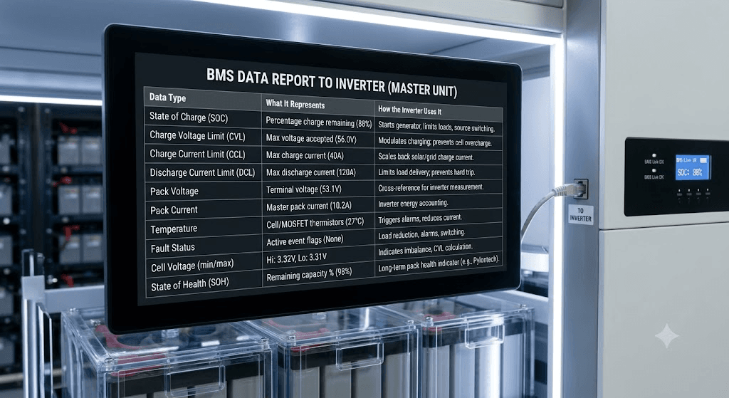
Regardless of architecture, the master BMS is responsible for transmitting the data the inverter needs to make intelligent charging and discharging decisions. The following table documents every data type that a fully capable master BMS transmits and how the inverter uses each one.
| Data Type | What It Represents | How the Inverter Uses It |
| State of Charge (SOC) | Percentage charge remaining in the battery bank. | Used by inverter to decide when to start generator, when to limit loads, when to switch sources. |
| Charge Voltage Limit (CVL) | Maximum voltage the BMS accepts from charger at this moment. | Inverter modulates charge voltage to stay below CVL. Prevents cell overcharge even if pack is charging fast. |
| Charge Current Limit (CCL) | Maximum charge current the BMS accepts right now. | Inverter scales back solar or grid charge current when CCL is reduced (e.g. high temperature, near full charge). |
| Discharge Current Limit (DCL) | Maximum discharge current the BMS permits. | Inverter limits load delivery to DCL. Prevents overcurrent without a hard BMS trip. |
| Pack voltage | Total terminal voltage of the master pack. | Cross-reference for inverter’s own voltage measurement. |
| Pack current | Charge or discharge current flowing through master pack. | Inverter uses this for its own energy accounting. |
| Temperature | Cell and MOSFET temperatures from master BMS thermistors. | Inverter may trigger alarms or reduce current based on high temperature signals. |
| Fault status | Active protection event flags: OVP, UVP, OCP, OTP, communication fault. | Inverter responds to fault flags with load reduction, alarm triggering, or source switching. |
| Cell voltage (min/max) | Highest and lowest individual cell voltage in the master pack. | Indicates imbalance to the inverter. Some inverters display this directly; others use it for CVL calculation. |
| State of Health (SOH) | Remaining capacity as percentage of original (where supported). | Long-term pack health indicator. Not all BMS units transmit this; Pylontech and premium commercial batteries include it. |
The engineering depth of how CVL, CCL, and DCL interact with inverter behaviour in real time is covered in our article: CVL, CCL, and DCL: dynamic battery limits in real time. Understanding these three values is essential for understanding what the master BMS is actually doing for the system when it reports them correctly.
Pylontech Master-Slave Architecture
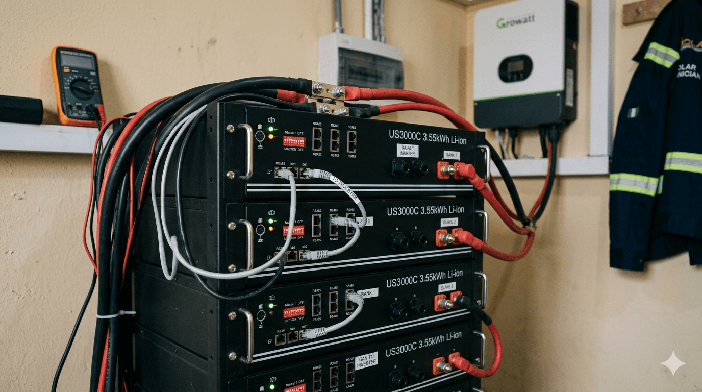
Pylontech batteries are the most common sealed lithium battery in the Nigerian market with integrated BMS and native multi-pack communication. Their master-slave implementation is a genuine aggregation architecture: the master has real-time visibility of all slave packs and presents a unified view to the inverter.
The Inter-Unit Communication Layer
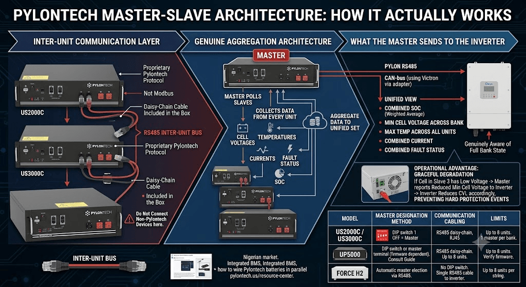
Pylontech uses RS485 for inter-unit communication, running on a proprietary Pylontech protocol over the same physical interface that connects to the inverter. Read our article on: Proprietary vs Open Battery Protocols The daisy-chain communication cable (included in the Pylontech box) creates a RS485 bus between all units in the bank. The master polls each slave periodically, collects cell voltages, temperatures, currents, fault status, and SOC from each unit, and aggregates this data.
The master’s aggregated data includes: combined pack SOC (weighted average from all units), minimum cell voltage across the entire bank, maximum cell voltage across the entire bank, maximum temperature across all units, combined current, and combined fault status (the master reports any fault from any unit in the bank). This aggregated data set is what the inverter receives, making the inverter genuinely aware of the full bank state rather than just one pack.
Pylontech’s inter-unit communication protocol is proprietary and not published externally. It is not the same RS485 Modbus register map used for inverter communication. If you attempt to connect a non-Pylontech device to the Pylontech inter-unit bus, it will not communicate correctly and may interfere with the inter-unit polling.
| Model | Master Designation Method | Communication Cabling | Limits |
| US2000C / US3000C | DIP switch on front panel. Switch 1 OFF = Master. All slaves have Switch 1 ON. | RS485 cable daisy-chained from master to slave 1 to slave 2. RJ45 connectors. Pylontech cable included in box. | Up to 8 units. Maximum 1 master per bank. |
| UP5000 | DIP switch or dedicated master terminal depending on firmware version. Consult Pylontech installation guide. | Same daisy-chain RS485 as US-series. Master connects to inverter RS485 port. | Up to 8 units. Verify firmware version at pylontech.us before configuration. |
| Force H2 | Automatic master election via RS485 inter-unit communication. No manual DIP switch required on H2 series. | RS485 daisy-chain between units. Single RS485 cable from designated master position to inverter. | Up to 8 units per string. Multiple strings possible on some inverters. |
The specific cabling procedure for Pylontech parallel installations, including the power cable order and the RS485 daisy-chain sequence, is in our article: how to wire Pylontech batteries in parallel. Pylontech also maintains model-specific installation guides at pylontech.us/resource-center which document DIP switch positions for each model generation.
What the Pylontech Master Sends to the Inverter
The Pylontech master transmits on the PYLON RS485 protocol, which is natively supported by Deye, Growatt, Solis, Goodwe, SMA, and Victron (via adapter). The data transmitted is the aggregated bank data: the SOC reflects all units, the minimum cell voltage is the lowest cell across all packs (not just the master pack), and the maximum temperature is the highest reading anywhere in the bank.
That’s the real operational difference compared to JK BMS single-master. If cell 7 in Pack 3 is going soft and its voltage is sagging below the others, the Pylontech master catches it it reports the reduced minimum cell voltage to the inverter, which starts trimming CVL before anything hard-trips. The system degrades gracefully. You get a warning, not a sudden disconnect.
JK BMS Multi-Pack Single-Master Without Inter-BMS Communication
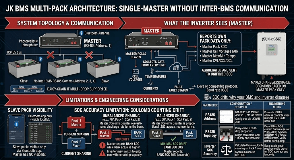
The JK BMS architecture in a multi-pack system is fundamentally different from Pylontech’s. There is no communication between JK BMS units. Each JK BMS operates as a completely independent unit. One unit is designated the master for inverter communication purposes, and the others are slaves in name only: they are really just independent protection units that happen to be monitored via Bluetooth.
| Parameter | Configuration / Behaviour | Engineering Notes |
| RS485 address assignment | Set to address 1 on the master BMS. Set to address 2, 3, etc. on slave units. Configured in the JK BMS Bluetooth app under Communication Settings. | Prevents address conflicts on the RS485 bus when multiple BMS units share the same bus. |
| RS485 topology | Daisy-chain if inverter supports multi-drop polling (address 1, 2, 3 in sequence). Single cable from address 1 to inverter if inverter supports only one BMS unit. | The Deye SUN-xK-SG series current firmware (as of 2025-2026) typically supports only single BMS communication. Verify at deye.com.cn/global before configuring multi-drop. |
| What master reports | Master BMS (address 1) reports its own pack’s SOC, cell voltages, temperatures, CVL, CCL, DCL to the inverter via RS485. | The inverter makes charging and discharging decisions based on master BMS data only. Slave pack data is visible only via Bluetooth app. |
| What slaves do | Each slave BMS protects its own cells completely independently. No communication between slave and master BMS at the JK BMS level. Slaves are truly independent protection units. | This is the key limitation of the JK BMS multi-pack architecture versus true master-slave systems like Pylontech: there is no inter-BMS data aggregation. |
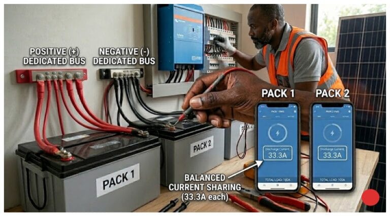
| Inverter SOC accuracy | The master BMS SOC is calculated from coulomb counting on Pack 1 only. In a well-balanced two-pack system with equal current sharing, Pack 1’s SOC approximates the combined bank SOC. In a poorly balanced system, it diverges. | This is why current sharing verification and equal cable lengths are critical for maintaining inverter SOC accuracy in JK BMS multi-pack systems. |
The SOC Accuracy Limitation
The most significant limitation of JK BMS single-master architecture is SOC accuracy for the combined bank. The master JK BMS counts coulombs flowing through Pack 1. It divides by Pack 1’s rated capacity to calculate SOC. It reports this to the inverter as the battery bank SOC.
If current sharing is equal (Pack 1 and Pack 2 each carrying 50A at 100A total load), Pack 1’s coulomb count is proportionally equal to Pack 2’s. The SOC calculated from Pack 1 is approximately representative of the full bank. The error is small.
If current sharing is unequal (Pack 1 carrying 70A and Pack 2 carrying 30A due to unequal cable lengths), Pack 1’s coulomb count overestimates the bank discharge rate. The master BMS calculates an SOC that is declining faster than the combined bank actually is. The inverter switches to generator backup while the combined bank still has meaningful capacity remaining.
This is why equal cable lengths in a JK BMS multi-pack system aren’t just about even wear they’re what keeps your SOC reading honest. If Pack 1 is pulling more current than Pack 2, the inverter will think the bank is emptying faster than it actually is. Your generator kicks on while you still have usable capacity sitting in Pack 2.
Configuring JK BMS Multi-Pack for Deye and Growatt
The configuration procedure for a two-pack JK BMS system with a Deye SUN-5K-SG inverter:
- Open JK BMS Bluetooth app on Pack 1. Navigate to Communication Settings. Set RS485 address to 1. Set baud rate to 9600. Set protocol to Deye or compatible variant for your inverter.
- Open JK BMS Bluetooth app on Pack 2. Set RS485 address to 2. Same baud rate and protocol.
- Connect Pack 1 RS485 A, B, and GND terminals to the Deye RS485 BMS port.
- If the Deye firmware supports multi-drop BMS polling: connect Pack 2 RS485 in daisy-chain after Pack 1 on the same RS485 bus. Confirm Deye firmware version supports this at deye.com.cn/global before attempting.
- If Deye firmware does not support multi-drop: leave Pack 2 RS485 unconnected to the inverter. Monitor Pack 2 via Bluetooth app only.
- In the Deye inverter settings: navigate to Battery Settings, select battery type to match JK BMS or compatible protocol. Verify inverter display shows SOC as percentage.
FIRMWARE CHECK IS MANDATORY
One thing worth confirming before you wire anything: Deye firmware versions differ significantly in which battery protocols and multi-BMS configurations they support. Don’t assume multi-drop BMS polling works on your specific unit. Check the firmware release notes at deye.com.cn/global before commissioning any multi-BMS setup
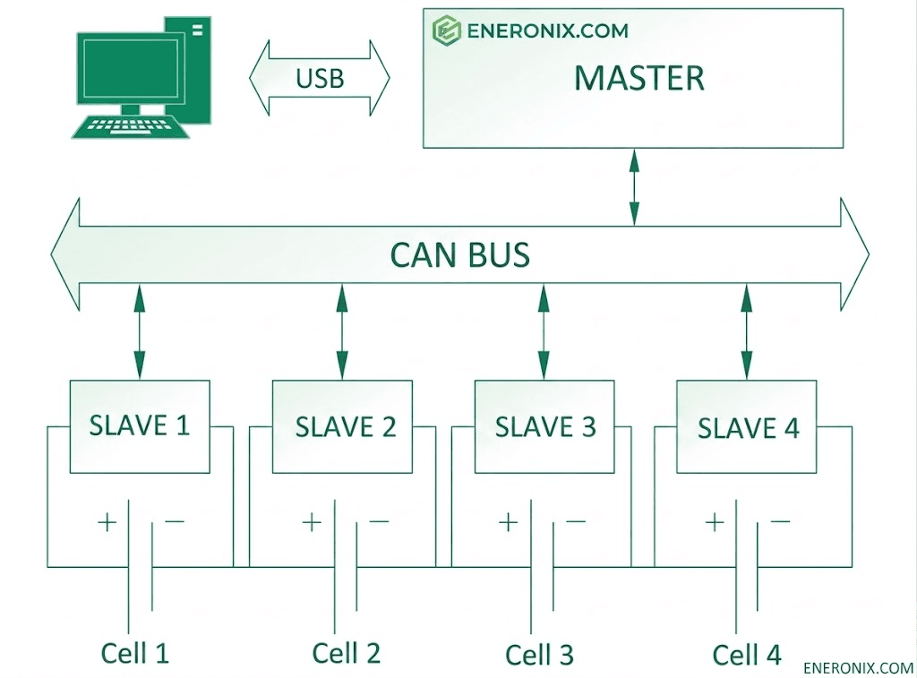
Victron Multi-BMS: Peer-to-Peer on VE.Can
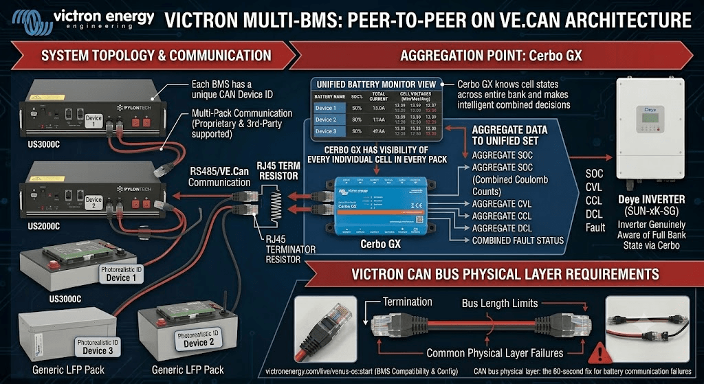
Victron’s approach to multi-BMS communication is architecturally different from both Pylontech and JK BMS. The Victron Cerbo GX (or CCGX) acts as the aggregation point rather than any single battery BMS acting as master. Each BMS connects to the VE.Can bus with a unique CAN device ID, and the Cerbo GX collects data from all of them simultaneously.
In this architecture, the Cerbo GX has visibility of every individual cell in every pack connected to the VE.Can bus, presented in a unified battery monitor view. It calculates the aggregate SOC from the combined coulomb counts of all connected BMS units. It transmits the aggregated CVL, CCL, and DCL to the inverter via the Victron internal communication bus.
This is genuinely the most capable multi-pack communication architecture available in the consumer solar market. The Cerbo GX knows the state of every cell across every pack and makes intelligent combined decisions. Full documentation for this architecture is available at victronenergy.com/live/venus-os:start, including the specific BMS compatibility list and configuration instructions for third-party BMS units on VE.Can.
For the CAN bus physical layer requirements that must be met when connecting multiple BMS units to a Victron VE.Can bus, our article on CAN bus physical layer: the 60-second fix for battery communication failures covers termination, bus length, and the most common physical layer failures that prevent multi-device VE.Can communication from working correctly.
What Happens When the Master BMS Fails
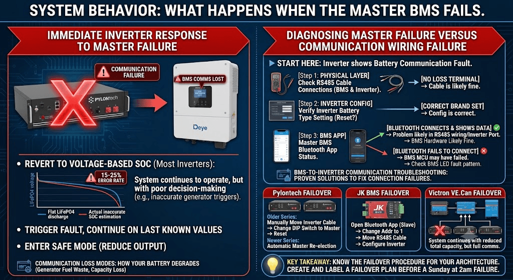
In every architecture, the master BMS is a single point of communication failure. If it develops a fault, the inverter loses its battery data source. How the system responds depends on the inverter and the architecture.
Immediate Inverter Response to Master Failure
When the inverter loses BMS communication, it typically does one of three things: it reverts to voltage-based SOC estimation (most Deye, Growatt, and Solis models), it triggers a communication fault alarm while continuing to operate on last known values (some models), or it enters a safe mode and reduces output significantly until communication is restored (commercial-grade systems).
For LiFePO4 chemistry, voltage-based SOC estimation is inaccurate by 15 to 25% across most of the discharge range due to the flat voltage curve. The system continues to operate but makes poor decisions about generator triggers, charge termination, and load management.
The specific degradation that occurs when a battery system runs on voltage-based SOC estimation for extended periods is documented in our article: communication loss modes: how your battery degrades when communication fails. The article quantifies the generator fuel waste and capacity loss that accumulate over weeks of communication-absent operation.
Diagnosing Master Failure Versus Communication Wiring Failure
When the inverter shows a battery communication fault, the root cause is not always the master BMS hardware. It is frequently the RS485 cable. Before assuming the master BMS has failed:
- Check the RS485 cable physical connections at both the BMS terminal block and the inverter RS485 port. A single loose wire terminal on the A or B conductor stops communication entirely.
- Verify the inverter battery type setting has not been reset (firmware updates sometimes reset settings to defaults). Set it back to the correct BMS brand.
- Check whether the master BMS Bluetooth app still connects and shows correct cell data. If Bluetooth works but RS485 does not, the BMS hardware is likely fine and the issue is in the RS485 wiring or inverter communication port.
- If Bluetooth also fails to connect, the BMS MCU may have failed. Check if the BMS LED indicators show any fault pattern.
The complete step-by-step BMS-to-inverter communication diagnostic procedure is in our article: BMS-to-inverter communication troubleshooting: proven solutions to fix connection failures. The diagnostic tree in that article distinguishes between hardware BMS failure, RS485 physical layer problems, and inverter configuration issues.
Failover Procedures by Architecture
For Pylontech systems: if the master unit develops a fault and the system supports automatic master re-election (Force H2 series and some US-series firmware), a slave automatically promotes itself to master after detecting master absence. For older US2000C and US3000C: manually move the RS485 inverter cable to a different unit, change that unit’s DIP switch to master position, and reset the original master unit.
For JK BMS single-master systems: open the Bluetooth app on Pack 2’s BMS and change its RS485 address from 2 to 1. This promotes it to master. Move the RS485 cable from the failed Pack 1 BMS to Pack 2’s RS485 terminals. Configure inverter to recognise the new master. This takes approximately 5 minutes.
For Victron VE.Can systems: if one BMS fails and disconnects from VE.Can, the Cerbo GX simply continues aggregating from the remaining connected units. The aggregate SOC calculation adjusts for the missing pack. The system continues operating with reduced total capacity but full communication for the remaining packs.
KEY TAKEAWAY
Know your failover procedure before you need it. Write it on a piece of paper and tape it inside the battery enclosure. Every multi-pack system needs a clear answer to “what do I do if the master BMS fails at 2am on Sunday” because that’s exactly when it will happen.
Choosing the Right Architecture for Your Installation
For most Nigerian installations, the architecture you end up with is largely determined by what’s already on site. If you’re running Pylontech batteries, use their native master-slave system follow the Pylontech installation guide for your specific model and don’t try to improvise around it. It’s the most accurate multi-pack communication available for sealed batteries in this market.
If you’re building DIY packs with JK BMS units and connecting to a Deye or Growatt, you’re in single-master territory. Keep cable lengths equal, monitor your slaves via Bluetooth, and accept that your inverter only knows what Pack 1 is doing.
For Victron systems, VE.Can is the right path. If you’re running JK BMS CAN-variant units, connect all of them to the VE.Can bus with unique CAN IDs. If you’re mixing Pylontech with Victron, the Pylontech RS485 master talks to the Victron via the Pylontech-to-VE.Can adapter cable.
Once you’re past four packs, commercial-grade systems from BYD, Pylontech Force H series, or CATL come with factory-integrated multi-pack aggregation, SOH tracking, remote monitoring, and automatic failover built in. At that scale, trying to engineer it yourself with individual BMS units costs more in commissioning time than the premium battery cost.
Frequently Asked Questions
What is master-slave BMS architecture?
Master-slave BMS architecture is a communication design where one BMS unit (the master) handles all data exchange with the inverter on behalf of the entire battery bank, while other BMS units (the slaves) protect their individual packs and report data to the master. In a true master-slave system like Pylontech, the master aggregates cell data from all slave units and presents a unified SOC, CVL, CCL, and DCL to the inverter. In a simpler single-master configuration used with JK BMS multi-pack systems, the master reports its own pack data to the inverter while slaves operate as independent protection units without inter-BMS communication.
How do I set up master and slave BMS units?
For Pylontech batteries: set the master using the DIP switch on the front panel (switch position varies by model, consult the Pylontech installation guide at pylontech.us). Connect RS485 cables in a daisy-chain from master to slave 1 to slave 2 and so on. Connect the master’s RS485 port to the inverter. For JK BMS multi-pack systems: set the master to RS485 address 1 in the JK BMS Bluetooth app. Set each slave to a unique address (2, 3, etc.). Connect the master’s RS485 terminal to the inverter RS485 port. Slave JK BMS units are monitored via Bluetooth only, with no RS485 link between units.
What happens if the master BMS fails in a multi-pack system?
In a true master-slave system: the inverter loses BMS communication and reverts to voltage-based SOC estimation. The slave packs continue operating with their own protection. For Pylontech and BYD systems, some configurations support automatic master re-election where a slave promotes itself to master after detecting master failure. In a JK BMS single-master configuration: the inverter loses RS485 communication and reverts to voltage-based SOC. The other packs continue operating normally. To restore communication, configure a new master by changing the RS485 address of another unit to address 1 via the Bluetooth app.
Can I use different BMS brands in the same multi-pack system?
Not recommended for communication integration. Different BMS brands use different RS485 register maps, different protocol conventions, and different CVL/CCL/DCL broadcasting formats. Mixing brands in a system where the inverter polls multiple BMS units creates protocol conflicts. For power protection, different brands in parallel is physically possible since each BMS protects its own pack independently of the others. But for communication-level integration and accurate aggregate SOC, use identical BMS units from the same manufacturer.
Does the slave BMS need to communicate with the inverter?
In a true master-slave architecture: no. The slave BMS communicates with the master BMS, which aggregates and forwards data to the inverter. The slave has no direct inverter communication path. In a JK BMS single-master architecture: slave units have no communication with the inverter at all. They are monitored via Bluetooth app only. In a peer-to-peer multi-BMS architecture (like Victron VE.Can): every BMS communicates directly with the Victron GX device, which aggregates all data.
How does the master BMS calculate SOC for the whole bank?
In a true master-slave system with inter-BMS communication: the master collects current readings from all slave units and sums them for its coulomb counting. It receives the cell data from all units and uses the combined data for a more accurate SOC estimate of the full bank. In a JK BMS single-master system: the master only coulomb-counts its own pack’s current.
It has no knowledge of what the slave packs are doing. The accuracy of the master’s SOC as a representation of the full bank depends entirely on whether current sharing between packs is equal. Equal current sharing means the master’s coulomb count is proportionally representative of the full bank. Unequal sharing means the master’s SOC drifts from the true bank state.

I am Engr. Ubokobong Ekpenyong, a solar specialist and lithium battery systems engineer with over five years of hands-on experience designing, assembling, and commissioning off-grid solar and energy storage systems. My work focuses on lithium battery pack architecture, BMS configuration, and system reliability in off-grid and high-demand environments.