A solar installer in Abuja reports that a 48V 200Ah LiFePO4 battery bank is delivering only 60% of its expected runtime after 14 months of service. The inverter shows no faults. The BMS has never tripped. Charging looks normal. But the system runs out of power two hours earlier every night than it did when it was new.
The owner assumes the cells are degraded. The installer suspects a faulty BMS. Both are wrong.
The cells are mostly healthy. The BMS is working correctly. What has happened is that the cells have drifted apart in state of charge over 14 months of daily cycling, and the pack is now delivering 60% of its rated capacity not because 40% of the cells have failed, but because the gap between the strongest and weakest cell has grown to the point where the pack trips its voltage limits 40% earlier than a balanced pack would.
This is cell imbalance. It is the most common cause of premature capacity loss in lithium battery packs, it is almost entirely preventable with the right BMS specification, and it is almost completely invisible without per-cell monitoring.
This article explains why cells go out of balance, how the divergence compounds over time, what it does to pack performance, and exactly how the BMS balancing circuit detects and corrects it in LiFePO4 and other lithium chemistry packs.
This is the final article in the Eneronix Phase 1 BMS foundations cluster. For the full picture of what a BMS does and why it is non-negotiable, the complete series starts with What Is a BMS? 7 Essential BMS Functions.
What Cell Imbalance Is and Why It Matters
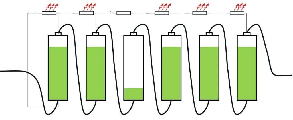
Cell imbalance in a series-connected battery pack means that the individual cells have different states of charge at the same point in the charge or discharge cycle. Some cells are more charged than others, not because they hold more energy but because they reached the same apparent pack terminal voltage from different starting points.
In a perfectly balanced pack, all 16 cells in a 16S LiFePO4 configuration reach their charge termination voltage simultaneously. All 16 cells hit their discharge cutoff voltage simultaneously. The pack delivers its full rated capacity on every cycle because no single cell is limiting the others.
In an imbalanced pack, one or more cells reach voltage limits ahead of the others. The BMS, correctly doing its job, terminates charging when the first cell hits OVP and terminates discharging when the first cell hits UVP. The stronger cells still have capacity in reserve. But the pack is already disconnected. That reserved capacity in the stronger cells is inaccessible.
The usable capacity of the pack is therefore not determined by the average cell capacity. It is determined by the weakest cell. As that weakest cell’s state of charge diverges further from its neighbours, the amount of inaccessible capacity in the stronger cells grows. The pack delivers progressively less runtime until the gap between cells is large enough to be obviously noticeable.
The painful reality: in the scenario described in the introduction, the pack may still have 95% of its original cell capacity intact. The 40% reduction in runtime is not from cell degradation. It is from imbalance preventing access to capacity that is physically present in the pack.
Why Cells Go Out of Balance:
Cell imbalance does not have a single cause. It is the cumulative result of several independent sources of divergence that each contribute incrementally and compound over time. Understanding each source is essential for designing systems that manage imbalance effectively.
Root Cause
Mechanism
Onset Timeline
Severity if Unmanaged
Factory capacity variation
Cells from the same batch have actual capacities within a tolerance band of 1 to 5%. A 100Ah cell may genuinely hold 96Ah or 104Ah.
Immediately from first cycle
Low to moderate initially, compounds over time
Self-discharge rate variation
Individual cells lose charge at slightly different rates when sitting at rest. A cell with 0.5% higher monthly self-discharge enters every charge cycle at a fractionally lower SOC.
Continuous from day one
Low initially, moderate after 12 to 24 months
Internal resistance variation
Cells with higher internal resistance show more voltage drop under load, appearing to be at a lower state than they actually are. Resistance diverges as cells age at different rates.
Develops over first 100 to 500 cycles
Moderate to high in aged packs
Temperature gradient
Cells in different positions experience different ambient and self-heating temperatures. Warmer cells have higher self-discharge and age faster, developing lower capacity over time.
Develops over 6 to 18 months in hot climates
High in poorly ventilated Nigerian installations
Differential aging
Cells subject to more thermal stress, deeper cycling, or more frequent high-current events degrade faster than protected cells in the same string.
Develops over months to years
High in systems with uneven load distribution or poor thermal management
Electrolyte dry-out (aged cells)
In aging cells, electrolyte is gradually consumed by side reactions. The rate differs by cell position and thermal history, causing capacity to diverge.
Appears after 2 to 5 years
Very high in old packs approaching end of life
Mixed cell batches
Combining cells of different ages or different production batches creates immediate large capacity mismatches that the BMS balancing circuit may not be able to correct.
Immediate
Very high, often severe
Factory Capacity Variation
No two lithium cells are identical, even from the same production batch. Manufacturing tolerances in electrode coating thickness, electrolyte volume, separator porosity, and formation cycling all introduce small variations in actual cell capacity. A cell spec sheet may show 100Ah nominal, but individual cells from that batch genuinely range from 97Ah to 103Ah.
In a series-connected pack, this matters immediately. The 97Ah cell fills 3% faster than the 103Ah cell on every charge cycle. It also empties 3% faster on every discharge cycle. After 100 cycles of daily deep cycling, this 3% inherent mismatch has produced a measurable and growing voltage divergence at the charge and discharge endpoints.
This is why cell matching matters so much when building DIY packs. Selecting cells from the same production batch, testing each cell’s actual capacity, and discarding outliers before assembly reduces the initial imbalance to less than 1%. A pack assembled from well-matched cells starts with a significantly smaller divergence problem than one assembled from random cells with unknown tolerance spread.
Self-Discharge Rate Variation
Lithium cells self-discharge when sitting at rest, losing a fraction of their charge without delivering any energy to a load. For LiFePO4, the typical self-discharge rate is 1 to 3% of capacity per month. For NMC, it is 2 to 5% per month.
The critical point is that individual cells self-discharge at different rates. A cell with a slightly higher self-discharge rate (perhaps due to minor internal contamination from the manufacturing process, a slightly thicker SEI layer, or a marginal separator defect) loses charge faster than its neighbours during storage and between cycles.
Over weeks and months of daily cycling, this self-discharge differential causes one cell to enter each charge cycle at a consistently lower SOC than the others. The BMS charges all cells at the same current (series connection enforces this). The lower-starting cell reaches full charge at a different point in the cycle than its neighbours. Without balancing to correct this offset, it diverges progressively.
Self-discharge imbalance is detectable in the BMS app by observing cell voltages after the pack has been at rest for 24 to 48 hours without charge or discharge. A cell whose voltage has dropped more than 30 to 50mV below its neighbours during this rest period has a higher-than-normal self-discharge rate. This is often an early indicator of a cell with an internal defect.
Internal Resistance Variation and Growth
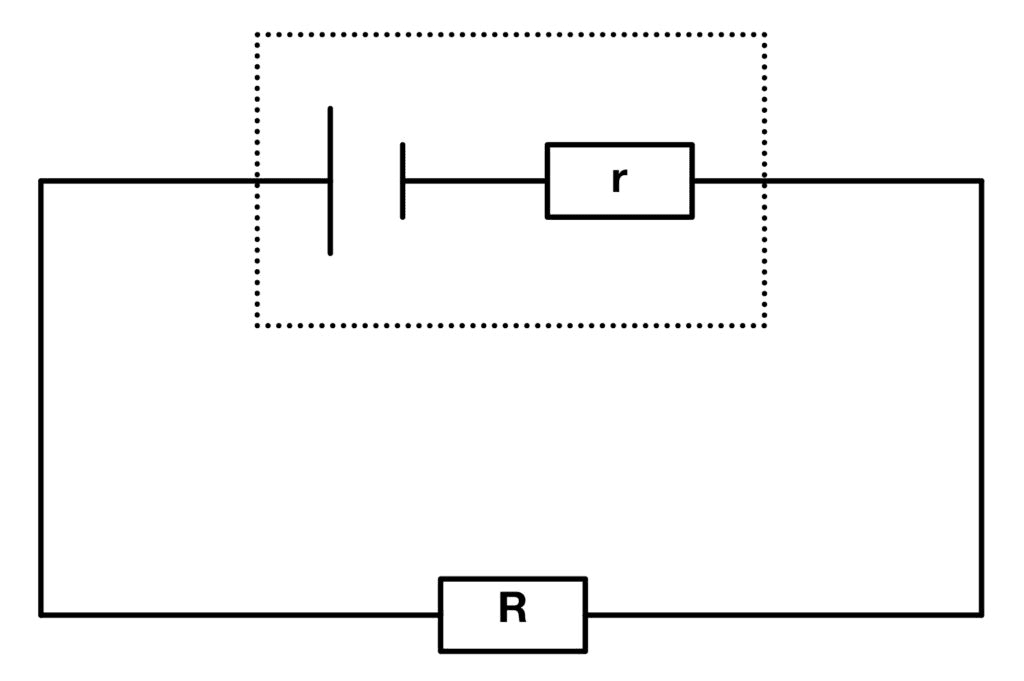
Internal resistance is the opposition to current flow inside the cell. It determines how much the cell voltage drops under load (discharge) and how much it rises above its equilibrium voltage when being charged.
At the pack level, all cells carry the same current (series connection). But cells with higher internal resistance experience a greater voltage drop under that current than low-resistance cells. Under a 100A discharge load, a cell with 2 milliohms of internal resistance drops 200mV from its open-circuit voltage. A cell with 4 milliohms drops 400mV. The higher-resistance cell appears to be at a lower state of charge than it actually is, because its voltage is depressed by the resistive drop.
This voltage depression can trigger the BMS UVP protection on the high-resistance cell before its actual state of charge has reached the cutoff threshold. The pack disconnects while the high-resistance cell still has usable energy, but the BMS correctly sees it as having reached its minimum voltage.
Internal resistance grows with age, temperature exposure, and cycle count. Cells in warmer positions in the pack age faster, develop higher internal resistance faster, and create increasingly large voltage-under-load discrepancies compared to cooler cells in the same string. In Nigerian installations where temperature gradients across a battery pack can exceed 10 degC, this differential aging from temperature alone can produce significant resistance spread within 18 to 24 months.
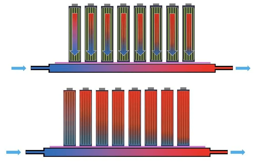
Temperature Gradients
Temperature is the most powerful accelerant of cell divergence in Nigerian field conditions. Lithium cell aging is thermally activated: the rate of every degradation mechanism (SEI layer growth, electrolyte decomposition, cathode structural change) increases exponentially with temperature. A cell at 45 degC ages at roughly twice the rate of a cell at 35 degC.
In a battery pack installed in a non-air-conditioned enclosure, cells in different positions experience different temperatures. The cell closest to the BMS PCB, which generates heat from its MOSFET switches and balance resistors, runs warmer than a cell at the far end of the stack. Cells near ventilation openings run cooler than cells in the centre of a tightly packed enclosure.
Over 12 to 18 months of daily cycling at 40 to 50 degC average enclosure temperatures, the cells in the warmest positions can lose 15 to 25% more capacity than cells in the coolest positions. This thermally-driven capacity divergence is entirely invisible without per-cell monitoring and builds up silently until the weakest (hottest) cells start triggering early voltage limit trips.
FIELD OBSERVATION
In Nigerian solar installations where battery capacity has dropped significantly within the first 18 to 24 months, temperature-gradient imbalance is the most frequently identified root cause upon inspection. The cells in the warmest positions in the pack consistently show the lowest capacity. The fix requires both cell replacement and redesign of the enclosure ventilation to eliminate the temperature gradient.
How Imbalance Compounds Over Cycles
Cell imbalance is not a stable condition. Once it begins, the mechanisms that cause it also accelerate it, creating a progressive spiral of divergence that worsens with every cycle.
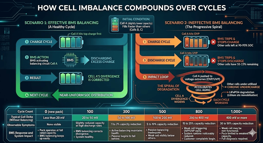
Here is the mechanism. A cell with slightly lower capacity (call it Cell A) fills faster than its neighbours. Each charge cycle, Cell A reaches the top of its charge curve slightly earlier than the other cells. At that point, one of two things happens:
If the BMS is balancing effectively, the balancing circuit activates on Cell A, dissipating or redirecting its excess charge until the other cells catch up. Cell A’s divergence is corrected. The pack cycles with near-uniform SOC distribution.
If the BMS is not balancing effectively (passive balancing too slow, or no balancing at all), Cell A routinely reaches OVP first. The BMS trips and stops charging. The other cells are left at 90 to 95% SOC. On the next discharge cycle, Cell A also hits UVP first, disconnecting the pack while the other cells have 10 to 15% remaining.
In scenario 2, Cell A is being pushed to the voltage extremes on every single cycle: to OVP on every charge, to UVP on every discharge. These voltage extremes are exactly the conditions that accelerate cell aging. Cell A ages faster than its neighbours, loses more capacity, and becomes even more divergent. Each cycle makes it worse. The gap between Cell A and the other cells widens progressively.
Meanwhile, the other cells are being undercharged (charge stops when Cell A hits OVP before they are full) and under-discharged (discharge stops when Cell A hits UVP before they are empty). The other cells are being under-utilised, which seems positive, but the chronic undercharge actually causes its own degradation in LiFePO4 cells through long-term lithium site immobilisation in the cathode.
The pack is now in a spiral: the weakest cell gets weaker faster, the other cells are chronically misused, and the total accessible capacity falls further every month.
Cycle Count
Typical Cell Delta (Without Balancing)
Observable Symptoms
BMS Response and System Impact
0 (new pack)
Less than 20 mV
None visible
Pack operates at full rated capacity. BMS balancing keeps up easily.
100
20 to 50 mV
Slightly reduced capacity at high discharge rates
BMS balancing corrects divergence during each CV phase. System healthy.
300
50 to 100 mV
1 to 3% capacity reduction
Active balancing maintains pack health. Passive balancing begins to fall behind.
500
100 to 200 mV
5 to 10% capacity reduction
Passive balancing clearly inadequate. Active balancing still maintaining reasonable health. Weak cell visibly below others in BMS app.
800
200 to 400 mV
15 to 25% capacity reduction
Weak cell triggering OVP early during charging and UVP early during discharge. System runtime noticeably reduced. Customer complaints begin.
1,000+
400 mV or more
30 to 50% capacity reduction
Weak cell may be non-functional. Pack is limited to the capacity of the weakest cell. BMS trips frequently. Full diagnosis and potential cell replacement required.
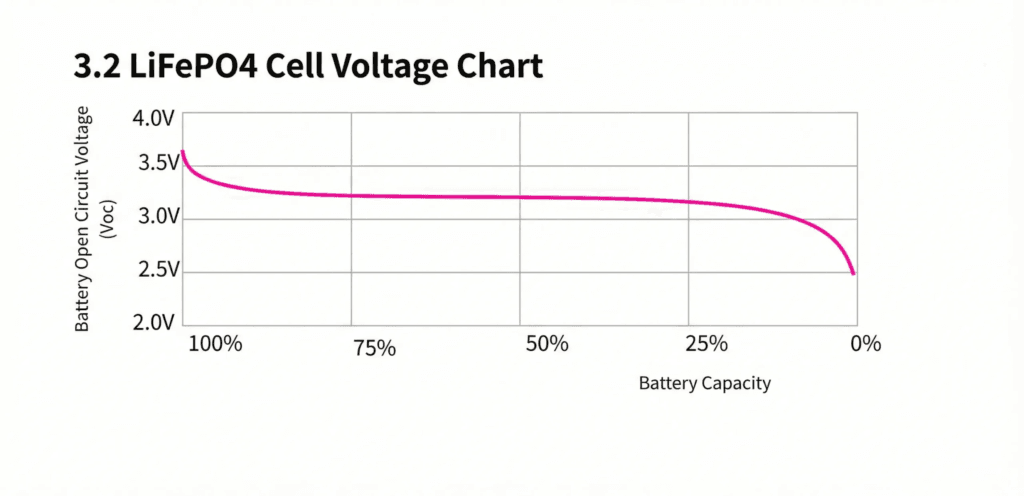
The LiFePO4 Flat Voltage Curve: Why It Makes Imbalance Harder to Detect and Correct
LiFePO4 is the best lithium chemistry for solar storage in nearly every respect. But it has one characteristic that makes managing cell imbalance technically harder than in NMC or NCA packs: its extraordinarily flat discharge voltage curve.
In an NMC pack, cell voltage changes measurably across most of the SOC range. A 10% SOC difference between two NMC cells produces a voltage difference of 100 to 200mV across most of the operating range. This is easily detectable by any BMS cell monitoring circuit and triggers passive balancing reliably.
In a LiFePO4 pack, cell voltage changes by only 50 to 100mV across the entire range from 20% to 90% SOC. A 10% SOC difference between two LiFePO4 cells produces a voltage difference of only 10 to 20mV across most of this range. This is at or below the trigger threshold of most passive BMS units and at the noise floor of many cell-monitoring ICs.
SOC Level
Strong Cell Voltage (LiFePO4)
Weak Cell Voltage (10% SOC lower)
Delta
Balancing Detectability
90% SOC
3.40V
3.38V
20 mV
Detectable. Most BMS units will activate balancing at this delta.
80% SOC
3.33V
3.31V
20 mV
Detectable but marginal. Some passive BMS units set balance threshold above 20mV and miss this.
70% SOC
3.30V
3.28V
20 mV
At the edge of detection for passive BMS units. Active balancers with 5mV threshold handle this correctly.
50% SOC
3.28V
3.26V
20 mV
Very difficult to detect reliably for voltage-triggered passive balancing. Measurement noise can mask this delta.
30% SOC
3.24V
3.22V
20 mV
Essentially undetectable by voltage-triggered passive balancing. Both cells appear nearly identical.
10% SOC
3.10V
2.90V
200 mV
Large detectable delta. But this is the discharge endpoint: the damage is already being done to the weak cell.
The table shows the core problem: the same 10% SOC imbalance that is detectable and correctable at the top of charge becomes nearly invisible in the middle of the discharge range. Passive balancing, triggered by voltage differences, can only act at the top of the charge curve where cell voltage differences are large enough to detect.
This means passive balancing in a LiFePO4 pack has only a narrow window of effectiveness per cycle: the CV phase at the top of charge when cells are above 3.35V and voltage differences are more pronounced. Outside this window, passive balancing cannot detect or correct imbalance. The cells spend 80 to 90% of each cycle in the flat portion of the curve where the passive BMS is effectively blind to their relative states.
Active balancing with a configurable low start threshold (5 to 15mV) addresses this directly by not relying on large voltage differences to trigger correction. The mechanics of this are covered in our dedicated article: active vs passive balancing: which BMS balancing method is better.
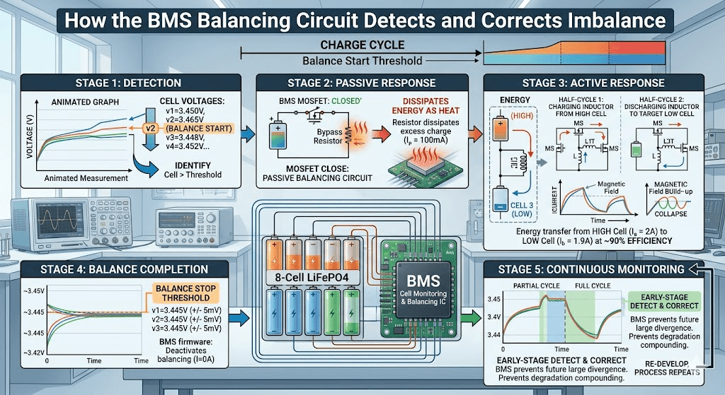
How the BMS Balancing Circuit Detects and Corrects Imbalance
The BMS balancing circuit is not a single component. It is a continuous monitoring and correction process that operates across the entire charge cycle. Understanding the specific stages of this process explains both why a good BMS keeps cells matched over thousands of cycles and why an inadequate BMS allows divergence to compound.
Balancing Stage
What Happens
Detection
The BMS cell monitoring IC reads all cell voltages simultaneously at a defined sample rate (typically every 100 to 500ms). The firmware compares each cell against the pack average and identifies cells above the balance start threshold.
Passive response
The BMS closes the MOSFET switch for the high cell, connecting a bypass resistor in parallel. Current flows through the resistor, dissipating energy as heat and slowing the cell’s voltage rise. The resistor remains engaged until the cell voltage drops back within the balance threshold of its neighbours.
Active response
The BMS activates the inductor-based switching circuit connected to the high cell. On each switching half-cycle, current flows from the high cell into the inductor, storing energy in the magnetic field. On the next half-cycle, the inductor releases that energy into the target low cell. The net result is energy transfer from high cell to low cell at 80 to 95% efficiency.
Balance completion
Balancing continues until all cells are within the configured balance stop threshold (typically 5 to 10mV). The BMS deactivates the balancing circuit. On the next charge cycle, if imbalance has re-developed, the process repeats.
Continuous monitoring
Even when balancing is inactive, the BMS continuously monitors cell voltages. If a cell’s voltage diverges from the pack by more than the balance start threshold at any point in the cycle, balancing reactivates. This continuous monitoring is what allows the BMS to catch early-stage imbalance before it compounds into large divergence.
The specific algorithms used in smart BMS firmware to detect imbalance in LiFePO4 packs, including the use of coulomb counting rather than voltage alone to identify SOC differences during the flat curve region, are covered in our article: how smart BMS balancing algorithms protect lithium battery packs.
The Balancing Current Requirement
The balancing circuit’s effectiveness is almost entirely determined by one parameter: balancing current. This is the current the BMS can actively transfer (active balancing) or dissipate (passive balancing) per cell per unit time.
Consider a 200Ah LiFePO4 pack where one cell has drifted 5% behind its neighbours in SOC. The energy difference represents 10Ah of charge that needs to be added to the lagging cell (or removed from the leading cells) to restore balance. At 100mA of passive balancing current, correcting this 10Ah imbalance takes 100 hours. The pack cycles daily. New imbalance is added each cycle. The 100mA passive BMS can never catch up.
At 2A of active balancing current, the same 10Ah imbalance is corrected in 5 hours. Within a single overnight charge cycle, the imbalance is resolved before the next day’s cycling adds more. The pack stays tight cycle after cycle.
This is why specifying balancing current is not a secondary detail. For any pack above 100Ah in daily solar service, balancing current is the primary specification that determines whether cell divergence will be managed or allowed to compound.
Top Balancing: When in the Cycle the BMS Corrects
Most BMS designs activate balancing during the CV (constant voltage) phase at the top of charge. This is called top balancing, and it is the standard approach for virtually all commercial lithium battery packs.
The CV phase is the period after the battery has been bulk charged to the target voltage and the charger is holding the voltage constant while tapering current. During this phase, the cells are near their full-charge voltage and the LiFePO4 voltage curve enters its steeper region above 3.35V per cell. Cell voltage differences are largest and most reliably detectable here.
The BMS app is the primary tool for identifying, quantifying, and tracking cell imbalance. Without per-cell monitoring, imbalance is invisible until it has grown large enough to produce noticeable symptoms. With the app, problems are identifiable months before they produce customer complaints.
Observed Symptom
Root Cause Analysis
Diagnostic Action
One cell consistently reaches full voltage first on every charge cycle
That cell has lower capacity than its neighbours. It fills faster. BMS should be balancing it down during CV phase.
Check if BMS balancing is active and effective. If cell delta is over 200mV, the cell may need capacity testing and possible replacement.
One cell consistently drops to low voltage first during discharge
Same root cause: lower capacity cell empties before the pack as a whole. BMS disconnects to protect it.
Monitor delta over several cycles. If it widens progressively, the cell is degrading. If stable, active balancing may correct it over time.
All cells gradually drift apart over months, none obviously weaker
Normal aging imbalance from capacity divergence and self-discharge variation. Expected behaviour in any series pack.
Verify BMS balancing is operating. If passive balancing, consider upgrading to active. If active, confirm balance start threshold is set to 5 to 15mV.
Large sudden delta appearing overnight with no change in system operation
Self-discharge variation: one or more cells have elevated self-discharge rates. Pack sat at rest and cells diverged.
Charge pack to full and monitor balance correction. If one cell self-discharges at a significantly higher rate than others, that cell has an internal defect and should be investigated.
BMS trips OVP during charging but most cells are not full
One cell has much lower capacity and hits OVP threshold while pack is only 70 to 80% full. Classic imbalanced pack symptom.
Identify the triggering cell via BMS app. Test its individual capacity. If significantly below rated capacity, it requires replacement.
Pack capacity has dropped 20 to 30% but all cells test individually normal
The cells individually hold their rated charge. The problem is cell-to-cell imbalance reducing accessible pack capacity.
Perform a full top balance: charge slowly to full and hold at CV until balancing current drops to near zero. Pack capacity may partially recover if cells are genuinely healthy but misaligned.
DIAGNOSTIC PRIORITY
The single most useful BMS app reading for imbalance diagnosis is the cell voltage spread during the CV charge phase. Open the app while the battery is charging and in the CV stage. Read all 16 cell voltages. On a healthy balanced pack, the spread should be under 30mV. A spread of 100mV or more indicates active imbalance that requires investigation. A spread of 300mV or more indicates a cell that is likely damaged or has significantly reduced capacity.
For a deeper treatment of how to interpret BMS data and use it to diagnose specific failure modes, our article on SOC drift: why your BMS and inverter disagree covers the most commonly misinterpreted BMS readings and their correct interpretation.
How to Prevent Cell Imbalance
Preventing cell imbalance is significantly easier and cheaper than correcting it after it has developed. The following practices, applied at the system design and commissioning stage, minimise the rate of imbalance accumulation and give the BMS balancing circuit the best possible conditions to maintain pack health.
Cell Selection and Matching
Source cells from the same production batch where possible. Test each cell’s actual capacity before assembly and reject cells that deviate more than 2% from the batch median. Match cells by capacity so that the pack string is as uniform as possible before the first charge cycle. A well-matched pack starts with near-zero imbalance, giving the balancing circuit a maintenance task rather than a correction task from day one.
Never mix cells from different manufacturers, different production batches, or different age groups in the same series string. A single aged cell in a string of new cells creates an immediate large imbalance that grows rapidly and cannot be corrected by balancing.
Enclosure Thermal Management
Design battery enclosures to maintain a uniform temperature across all cells in the pack. Position ventilation openings to encourage airflow across the full cell stack, not just one end. In high-power installations or in environments where ambient temperatures exceed 35 degC consistently, consider forced air cooling with a small fan circulating air across the cells.
The goal is to keep the temperature differential between the warmest and coolest cell in the stack below 5 degC. A pack with a 10 degC temperature gradient will develop measurable capacity divergence from thermally-driven differential aging within 12 to 18 months regardless of balancing quality.
The specific impact of temperature on battery lifespan and the ventilation strategies that mitigate it are covered in our guide: how to increase lithium battery lifespan.
BMS Specification: Active Balancing with Low Start Threshold
For any LiFePO4 pack above 100Ah in daily solar cycling service, specify a BMS with active balancing at a minimum of 1A balancing current. For 200Ah and above, 2A is the correct target. Set the balance start threshold to 10mV or lower to ensure correction begins before imbalance becomes large.
Passive balancing is adequate only for small packs (under 100Ah) with infrequent cycling. For daily solar storage at any meaningful capacity, passive balancing is not a cost-saving choice. It is an under-specification that will produce premature capacity loss within the first two years.
Before placing a new DIY pack into service, perform a full initial top balance. Connect the pack to a charger set to the correct CV voltage and hold at CV until the balancing current drops to near zero and all cell voltages are within 10mV of each other. This may take 6 to 12 hours for a large pack with poorly matched cells.
Starting the first service cycle with a well-balanced pack dramatically reduces the rate of imbalance accumulation over the first 100 cycles, which is the period when the balancing circuit is most likely to fall behind if starting from a misaligned state.
Conservative Depth of Discharge
Limiting depth of discharge to 80% rather than 100% keeps cells away from the voltage extremes where the LiFePO4 curve steepens and where small SOC differences between cells produce large voltage spikes. Cycling between 20% and 90% SOC rather than 0% and 100% gives the balancing circuit a more manageable correction task and reduces the thermal and electrochemical stress that accelerates differential aging.
What Most Installers Get Wrong About Cell Imbalance
MISTAKE 1
Diagnosing imbalance as cell failure and replacing the entire pack. In many cases, the cells are individually healthy but significantly imbalanced. A proper top balance, performed over 8 to 12 hours with good active balancing current, can recover 80 to 100% of the capacity that appeared to have been lost. Always attempt a full balancing correction before condemning a pack.
MISTAKE 2
Using pack terminal voltage to assess balance. Pack terminal voltage tells you nothing about individual cell states. A pack at 52.8V terminal voltage could have cells ranging from 3.15V to 3.45V. The only way to assess balance is to read individual cell voltages from the BMS app. Any installation without per-cell monitoring is operating without the ability to detect or quantify imbalance.
MISTAKE 3
Accepting that battery capacity declining to 80% after 18 months is normal degradation. In a correctly specified and maintained LiFePO4 system with active balancing, 80% capacity retention should occur after 2,000 to 4,000 cycles, not after 500 cycles. Capacity loss inside 18 months is almost always imbalance, thermal mismanagement, or misconfigured BMS thresholds, not normal cell wear.
MISTAKE 4
Not performing an initial top balance on new DIY packs. New cells from a supplier may have been stored at different SOC levels or discharged to different depths during transport. Assembling them without balancing first means the first charge cycle drives the highest-SOC cells to OVP while the lowest-SOC cells are still far from full. This first-cycle imbalance compounds immediately.
For a comprehensive catalogue of the system design and configuration decisions that lead to premature battery failure, our article on why most solar battery systems fail before year 2 identifies cell imbalance as one of the top three root causes documented across field installations.
Frequently Asked Questions
Why do lithium batteries go out of balance?
Lithium batteries go out of balance because the cells in a series pack are never perfectly identical. They leave the factory with small differences in capacity, internal resistance, and self-discharge rate. These differences cause cells to fill and empty at slightly different rates. Over hundreds of charge and discharge cycles, those small differences compound into significant imbalance. Temperature gradients across the cell stack, where cells in different positions experience different thermal conditions, accelerate the divergence further.
How do I know if my lithium battery is out of balance?
Connect to the BMS using its Bluetooth app or RS485 readout tool. Read the individual cell voltages in real time during charging, especially near the top of the charge cycle. On a well-balanced pack, all cells should be within 20 to 30mV of each other. A delta of 100mV or more between the highest and lowest cell during normal operation indicates significant imbalance. A delta above 300mV indicates a severely weak or damaged cell requiring immediate investigation.
What happens if lithium battery cells are out of balance?
When cells are out of balance, the weakest cell limits the entire pack in both directions. During charging, the weakest cell reaches the OVP threshold first, causing the BMS to stop charging before the other cells are full. During discharge, the weakest cell hits the UVP threshold first, causing the BMS to disconnect before the other cells are depleted. The result is reduced usable capacity from the full pack. Over time, the weak cell is chronically pushed to voltage extremes on every cycle, accelerating its degradation until it fails completely.
Can a BMS fix cell imbalance?
Yes, through its balancing circuit. A BMS with passive balancing dissipates excess charge from high cells as heat to bring them down to match the lower cells. A BMS with active balancing transfers energy from high cells to low cells using inductive circuits, correcting imbalance without wasting energy. Active balancing is significantly more effective for large packs with daily cycling because its higher balancing current can correct imbalance within a single charge cycle, while passive balancing may require many days.
How long does it take a BMS to balance cells?
It depends entirely on the balancing method and current. A passive BMS with 100mA balancing current correcting a 10Ah imbalance in a 200Ah pack requires approximately 100 hours of continuous balancing. In practice, balancing only occurs during the CV charge phase, giving perhaps 1 to 2 hours per day of effective balancing time. That extends correction time to 50 to 100 days. An active balancer with 2A balancing current corrects the same 10Ah imbalance in approximately 5 hours, within a single overnight charge cycle.
Does temperature cause cell imbalance?
Yes, temperature is one of the most significant contributors to cell imbalance in field installations. Cells at different positions in the pack experience different temperatures due to proximity to heat sources, airflow patterns, and proximity to the BMS PCB. Warmer cells have higher self-discharge rates and age faster. In Nigerian installations with poor enclosure ventilation, temperature gradients across a 16-cell stack can exceed 10 degC, producing measurable capacity divergence over 12 to 18 months even in initially well-matched packs.
What is the difference between top balancing and bottom balancing?
Top balancing aligns all cells at the top of charge, ensuring every cell reaches the same full-charge voltage at the end of each charge cycle. This is the standard operational approach for solar storage systems. Bottom balancing aligns all cells at the bottom of discharge. It is a cell preparation technique used by DIY builders before assembling a new pack: each cell is individually discharged to the same low voltage before the pack is connected. In normal operation, top balancing is the active ongoing strategy and bottom balancing is not an operational mode.
How do I prevent lithium battery cell imbalance?
The most effective prevention strategies are: specifying a BMS with active balancing and a low balance start threshold (5 to 15mV for LiFePO4), sourcing cells from the same production batch with tested capacity matching within 2%, maintaining consistent enclosure temperatures through proper ventilation to minimise thermal gradients across the cell stack, avoiding chronic deep discharge that pushes weak cells to voltage extremes on every cycle, and performing a full initial top balance when commissioning a new DIY pack before placing it in daily service.
Why does one cell keep going high during charging?
A cell that consistently reaches the high voltage limit before the rest of the pack has lower capacity than its neighbours. It fills faster because it has less space for lithium ions. This is the most common imbalance pattern in aging packs. The root cause is capacity divergence from differential aging. The BMS balancing circuit should be reducing that cell’s voltage during the CV phase. If the cell repeatedly trips OVP despite balancing, the capacity difference has become large enough that the balancing current cannot correct it fast enough. Investigate the cell’s individual capacity and consider whether it needs replacement.
Can mixing old and new cells cause imbalance?
Yes, significantly. Mixing cells of different ages in the same series string creates an immediate and severe imbalance problem. Aged cells have lower capacity and higher internal resistance. They fill faster and empty faster than new cells. The capacity mismatch can be 20 to 40% in cells that are 2 to 3 years old versus new cells. A BMS cannot balance away a 40% capacity mismatch. The correct approach is to replace all cells in a pack at the same time with cells from the same batch, or to use aged cells only in a pack with other cells of similar age and capacity.
I am Engr. Ubokobong Ekpenyong, a solar specialist and lithium battery systems engineer with over five years of hands-on experience designing, assembling, and commissioning off-grid solar and energy storage systems. My work focuses on lithium battery pack architecture, BMS configuration, and system reliability in off-grid and high-demand environments.
Contains information related to marketing campaigns of the user. These are shared with Google AdWords / Google Ads when the Google Ads and Google Analytics accounts are linked together.
90 days
__utma
ID used to identify users and sessions
2 years after last activity
__utmt
Used to monitor number of Google Analytics server requests
10 minutes
__utmb
Used to distinguish new sessions and visits. This cookie is set when the GA.js javascript library is loaded and there is no existing __utmb cookie. The cookie is updated every time data is sent to the Google Analytics server.
30 minutes after last activity
__utmc
Used only with old Urchin versions of Google Analytics and not with GA.js. Was used to distinguish between new sessions and visits at the end of a session.
End of session (browser)
__utmz
Contains information about the traffic source or campaign that directed user to the website. The cookie is set when the GA.js javascript is loaded and updated when data is sent to the Google Anaytics server
6 months after last activity
__utmv
Contains custom information set by the web developer via the _setCustomVar method in Google Analytics. This cookie is updated every time new data is sent to the Google Analytics server.
2 years after last activity
__utmx
Used to determine whether a user is included in an A / B or Multivariate test.
18 months
_ga
ID used to identify users
2 years
_gali
Used by Google Analytics to determine which links on a page are being clicked
30 seconds
_ga_
ID used to identify users
2 years
_gid
ID used to identify users for 24 hours after last activity
24 hours
_gat
Used to monitor number of Google Analytics server requests when using Google Tag Manager
1 minute
You can find more information in our Cookie Policy and .

")

")


