Why Your Solar Panel Is Not Charging Your Battery: A Field Diagnostic Guide
why your solar panel is not charging your battery? The problem is usually not the panel. Learn the 5 most common causes MPPT settings, low voltage, BMS protection, and wiring faults and how to diagnose them quickly.
The battery is at 40% at 11am. The sun is up, the panels look clean, and the controller LED is blinking. Most people assume the panel is faulty. In almost every case, that assumption is wrong and chasing it wastes time and money.
Solar charging failures follow a predictable pattern. The panel is the last component to fail. The real fault is almost always in the charge controller, the wiring, the BMS, or a configuration error made on the day of installation and never caught. This guide walks you through that failure pattern in the order it actually matters, from the most common faults to the least.
Why Your Solar Panel Is Not Charging Your Battery (Quick Diagnosis)
Most solar charging failures are not random. They follow a predictable pattern. Before diving into detailed testing, check these common causes in order of likelihood:
Wrong MPPT settings (most common): If the charge controller is configured for the wrong battery type or incorrect voltage limits, the battery will never reach full charge or may not charge at all.
Low PV voltage (very common): The solar panel voltage must exceed the battery voltage by a minimum margin for charging to begin. If it doesn’t, the controller will remain idle even in full sunlight.
BMS protection (common in lithium systems): If the battery’s Battery Management System (BMS) has tripped due to over-voltage, under-voltage, or temperature limits, it will block all charging.
Wiring losses (extremely common): Poor connections, especially faulty MC4 connectors or undersized cables, can cause voltage drops that prevent the controller from reaching its charging threshold.
Panel fault (rare): Solar panels are highly reliable. Actual panel failure is uncommon and usually only occurs with visible physical damage or severe degradation.
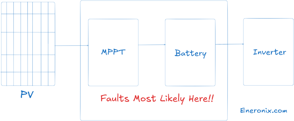
How the charging chain works and where it breaks
Energy moves through your system in one direction: panel, MPPT controller, battery. Each stage has conditions that must be met before the next stage begins. If any condition fails, the entire downstream chain stops.
Your MPPT controller is not a passive wire. It is an active regulator that continuously tracks the panel’s maximum power point and converts that into the correct charge voltage for your battery. It steps through three stages to do this: bulk (CV) (maximum current into a depleted battery), absorption (CC) (voltage held steady while current tapers off), and float (a maintenance trickle once the battery is full).
The controller will only begin charging if the panel input voltage exceeds the battery voltage by a minimum differential, typically 5V on a 12V system, scaling proportionally on 24V and 48V systems. Below that margin, the controller sits idle, even in full sun. A panel producing voltage is not the same as a system that is charging.
The battery side has its own gate: the BMS. On any lithium system, LiFePO4 or otherwise, the BMS monitors individual cell voltages and temperature. When any cell goes outside its safe operating window, the BMS opens the protection circuit and the battery disappears from the system entirely. No current in, no current out. The controller keeps running. Nothing charges. From the outside, a tripped BMS looks identical to a panel fault.
This chain is the mental model you need for every diagnostic: start at the controller, verify each link in sequence, and only arrive at the panel when everything else has been ruled out.
Fault 1: Controller configuration error (most common, most overlooked)
Image source: Reddit
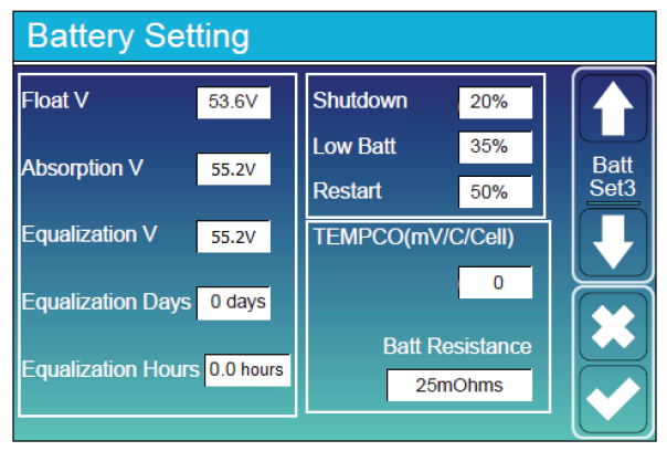
If your system was installed with the wrong battery type setting on the MPPT controller, it has never charged correctly and you may not have realised it.
A controller set to sealed lead-acid on a 48V LiFePO4 system will typically terminate absorption at around 56.4V and float at 54V. A LiFePO4 battery needs absorption at 58.4V and float around 53.6V. The result: the battery gets cut off at roughly 90 to 92% state of charge, every single cycle. Over time the battery appears to be weakening. The actual problem is that it was never fully charged from day one.
This is a five-minute check that costs nothing. Navigate to your controller’s battery settings. Confirm battery type, absorption voltage, and float voltage against the values in your battery manual. If your controller does not have a dedicated LiFePO4 profile, the voltages must be set manually. If it has no user-defined voltage option at all, it is not suitable for a lithium battery. See the MPPT charge controller selection guide before purchasing a replacement.
Do this check before anything else.
Fault 2: MPPT input voltage below the charging threshold
This is the most common cause of intermittent charging failures, particularly in the morning and on overcast days.
The controller will not start charging until panel voltage exceeds battery voltage by its required minimum differential. On a 48V system with a battery sitting at 50V, the controller needs to see at least 55V at its PV input terminals. If it is seeing 53V, it waits. Three things cause this, in order of how often they actually happen in the field:
Voltage drop across bad connectors.
A corroded or poorly crimped MC4 connector pair can have 50 to 100 milliohms of contact resistance. At 10A charging current, that is 0.5 to 1V dropped per connector pair. A DC run with three bad MC4 pairs can lose 1.5 to 3V before the power reaches the controller input. The panel terminals show a healthy Voc. The effective voltage under load, at the controller, is below threshold. This is the single most common wiring fault in field installations and the connector looks fine from the outside. A correctly crimped MC4 pair resists at least 50 to 80N of pull force. If your installer did not use a proper crimping tool, every connector in your system is a future fault.
Panel Voc too close to battery voltage.
On a 24V system running a single 24V nominal panel, the operating voltage margin is thin. Any loss, such as dust, partial cloud, or temperature-related Voc reduction on a hot afternoon, can push operating voltage below the controller’s minimum. This is a system sizing problem, not a fault you can fix with a multimeter. The MPPT sizing worked example covers the correct voltage margin calculation for common Nigerian system configurations.
Shading on a series string.
In a series-wired array, one shaded panel does not simply reduce output by its proportional share. It can collapse the entire string voltage, depending on irradiance level and bypass diode behaviour. A single panel at 30% output in a four-panel string can bring the whole string below MPPT threshold. How you wire your array directly affects how your system handles partial shading.
How to verify:
Measure Voc at the panel terminals with the PV input disconnected. Then reconnect and measure voltage at the MPPT PV input terminals under operating conditions. A gap greater than 2V in a well-wired system points to resistive losses in the wiring path. Trace your MC4 connectors. Look for discolouration, corrosion at the crimp point, or any connector that moves when you try to pull it apart.
Fault 3: BMS protection trip
A BMS trip is silent. The controller shows normal operation. The battery does not charge. There is no obvious fault indication anywhere.
BMS protection on a LiFePO4 battery is triggered by four conditions: over-voltage on charge (above 3.65V per cell, which is 58.4V on a 16-cell 48V bank), under-voltage on discharge (below 2.5 to 2.8V per cell, approximately 40 to 44.8V on a 48V bank), over-temperature (above 45 to 60 degrees Celsius depending on BMS grade), and cell imbalance severe enough that one weak cell hits its protection threshold before the pack reaches target voltage.
In Nigeria, the most common trigger is deep discharge from extended grid outages. A battery sitting at 20% state of charge or lower, or one that has been cut off by an inverter’s low battery protection, may have its BMS in protection mode when the sun comes up. The controller tries to charge. The BMS circuit is open. Nothing happens.
Some BMS units recover automatically after a rest period. Others require a manual reset via a dedicated button or a low-current wake-up charge through the correct charge port. Check your battery documentation for the exact procedure.
If your BMS is tripping repeatedly, the first thing to check is whether your controller’s absorption voltage exceeds the BMS over-voltage threshold. A controller set to 59V absorption on a battery with a 58.4V OVP will trip the BMS on every charge cycle without ever flagging a fault. This also accelerates cell degradation silently over time. For a detailed breakdown of how LiFePO4 battery protection systems behave under real operating conditions, including BMS reset behaviour, read the fundamentals guide.
Fault 4: MPPT controller thermal shutdown or overvoltage protection
Image source: Afore
Budget MPPT controllers and many mid-range units installed without proper ventilation enter thermal protection mode at internal temperatures of 65 to 75 degrees Celsius. In Lagos, Abuja, or Port Harcourt, ambient temperatures of 38 to 42 degrees Celsius are common. Add self-heating from conversion losses inside a sealed metal enclosure in direct sun, and the controller can hit thermal shutdown by early afternoon on a clear day.
It stops charging. It restarts when it cools. From the user’s perspective, the system charges in the morning, stops in the afternoon, and resumes toward evening. Many owners interpret this as the battery being full during the afternoon, or as the panels failing in direct sunlight. Neither is correct.
Check the controller’s surface temperature during peak hours. If you cannot hold your hand on it comfortably, it is running at or above its thermal limit. Controllers must be mounted in shaded, ventilated spaces, never in direct sun and never inside sealed enclosures without airflow.
Overvoltage shutdown is a separate fault. If your panel array’s open circuit voltage exceeds the controller’s maximum rated PV input voltage, the OVP activates and disables charging. This is common when panels are added to an existing system without recalculating combined string Voc. Note that Voc increases in cold weather. An array that operates within limits in July may trip OVP on cold harmattan mornings in December when panels are cool and Voc peaks. Verify total array Voc against your controller’s rated maximum before adding any panel to an existing string.
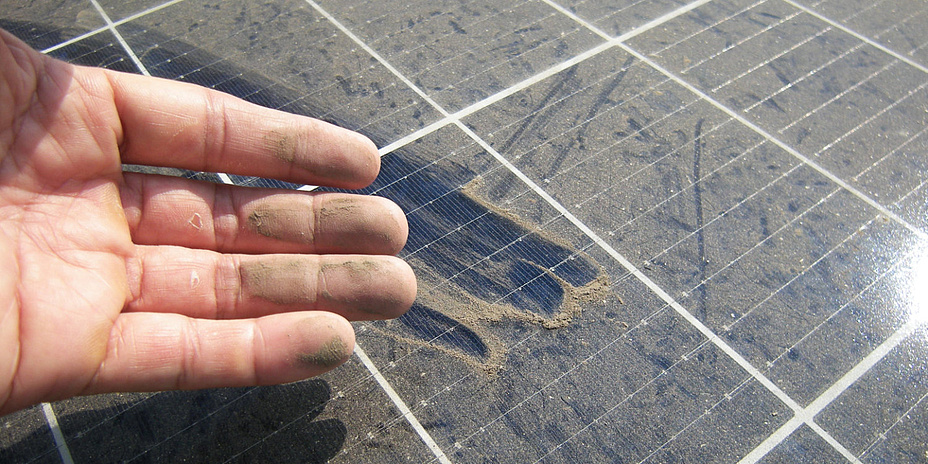
Fault 5: Dust, soiling, and irradiance reduction
image source: TU Graz
Harmattan dust accumulation on an unclean panel surface reduces output by 15 to 25% in heavy conditions. On a system with minimal voltage headroom, that reduction alone is enough to drop panel operating voltage below the MPPT charging threshold.
The diagnostic is immediate: wipe a small section of the panel clean with a damp cloth and observe whether output improves. If it does, the panels need a full clean.
The more important insight is this: if a 15 to 25% reduction from dust is enough to stop your system charging entirely, the system is undersized for the load and location. A correctly specified system has enough irradiance and voltage margin that incidental losses do not collapse operation. How actual panel output is derated in Nigerian field conditions is different from what the nameplate says. If your system is sensitive to dust or cloud cover, that gap is worth understanding before adding more panels.
This fault operates at the system level. Most system owners never identify it without being told to look for it.
Some inverter models cut off load at a battery voltage that is at or below what the MPPT controller needs to initiate a charge cycle. When the battery discharges to the inverter’s cutoff, say 44V on a 48V LiFePO4 system, the inverter disconnects the load. The battery rests at 43.5V. If the MPPT controller requires the battery to be above 44V before it can begin charging, the controller cannot start a charge cycle without a low-current wake-up from an external source, typically a generator-fed charger.
The system is stuck. The controller is healthy. The battery is healthy. The settings are simply not coordinated.
This is a commissioning error. Inverter low-voltage cutoff and MPPT minimum input differential must be set with awareness of each other. On a 48V LiFePO4 system, the inverter’s low battery cutoff should be set no lower than 46 to 47V to ensure the battery rests at a voltage the MPPT can recover from. If your system occasionally fails to resume solar charging after a deep discharge overnight, this is the first setting to investigate. The inverter battery percentage display guide covers related inverter voltage calibration issues that compound this problem.
Fault 7: Battery degradation and cell imbalance
Image Source: Fasmho Energy Systems
This is the least common cause of sudden charging failure, but it is the correct diagnosis when a battery that has been in service for two or more years starts showing the same symptom pattern as a BMS trip, without any clear external trigger.
A LiFePO4 cell that has drifted low in capacity will pull pack voltage down to BMS under-voltage protection prematurely on discharge. On charge, the same weak cell charges faster than the others and pushes its cell voltage to OVP threshold before the pack reaches target voltage. The BMS trips at what appears to be mid-charge. The controller stops. The battery never reaches full capacity.
The diagnostic observation: measure battery terminal voltage immediately after the controller stops charging. A healthy battery holds within 0.5 to 1V of absorption voltage during the float transition. A battery with significant cell imbalance will drop 3 to 5V within minutes of charge termination. The cells that absorbed charge quickly are already bleeding off energy. This voltage collapse is cell imbalance, not a normal float transition.
Passive balancing built into most BMS units cannot correct large capacity divergence. Active balancing hardware is required, and in some cases cell replacement is the only option. For a full breakdown of what causes LiFePO4 packs to fail over time and how to extend cycle life, including when active balancing is the right intervention, read the dedicated guide.
Diagnostic sequence: field checklist
Work through this in order. Do not skip ahead based on assumptions.
Read the controller display. Most MPPT controllers show active fault codes. An OV, OT, E01, or similar code tells you the fault category immediately. If there is a fault code active, diagnose that fault before touching anything else.
Check controller battery settings. Confirm battery type, absorption voltage, and float voltage match your battery’s specification sheet. Rules out the most common configuration error in five minutes.
Measure panel Voc. Disconnect the PV input from the controller. Measure open circuit voltage at the panel terminals. Compare to the panel datasheet Voc, derated for temperature. Voc drops approximately 0.3% per degree Celsius above 25 degrees. A 400W panel rated at 49.5V Voc at 25 degrees will produce roughly 46 to 47V Voc at 40 degrees ambient. Significantly lower than expected means shading, soiling, or panel damage.
Measure voltage at the MPPT PV input under load. Reconnect and let the system attempt to charge. Measure voltage at the controller’s PV input terminals. Compare to the Voc measured in Step 3. A gap greater than 2V indicates resistive losses in the wiring. Trace every MC4 connector and cable junction between the panels and the controller. For help sizing replacement DC cable correctly, use the cable and electrical calculator.
Check battery terminal voltage. Measure directly at the battery terminals. Zero volts or far below the nominal resting voltage means the BMS has opened the protection circuit. Follow your battery’s BMS reset procedure.
Check controller temperature. During peak afternoon hours, check whether the controller is too hot to hold your hand against. If it is, thermal shutdown is active or intermittent. Relocate to a ventilated, shaded location.
Check inverter cutoff settings. Confirm the inverter’s low battery cutoff voltage is set high enough that the battery can recover via solar charging without external assistance. On a 48V system, this means a cutoff no lower than 46 to 47V.
Only after all seven steps are clear without identifying a fault should you consider the panel itself as the source of the problem. Solar panels fail rarely and usually in ways that are physically obvious: delamination, cracked cells, or a failed bypass diode showing as a sharp output drop in one panel relative to adjacent panels under identical conditions.
Prevention: system design and maintenance decisions
Specify your MPPT controller for the array, not the battery alone. The controller’s maximum PV input voltage must be at least 10% above total array Voc under cold-weather conditions. If you are adding panels to an existing system, recalculate combined string Voc before making any connection. Overvoltage trips are silent and cumulative.
Require quality MC4 connectors and a pull-test at commissioning. A correctly crimped MC4 connector resists at least 50 to 80N of pull force. If your installer cannot demonstrate this or does not own a proper MC4 crimping tool, every connector in the system is a future fault. This is one of the most under-specified installation quality requirements in the market.
Never mount a controller inside a sealed enclosure without ventilation. A budget controller in an IP65 box in Nigerian ambient temperatures will throttle output on any clear afternoon. Thermal management is not optional.
Document system settings at commissioning. Write down your absorption voltage, float voltage, inverter low-voltage cutoff, and BMS protection thresholds. If system behaviour changes six months later, you need a baseline to compare against. Most owners do not have one.
Avoid chronic deep discharge cycles. A LiFePO4 battery regularly discharged below 20% state of charge has measurably shorter cycle life than one kept between 20 to 90%. The common off-grid mistakes that shorten system life covers this and related operational errors in detail.
The one thing to take away
Solar charging failures are almost always a system problem, not a panel problem. The panel is the most visible component and the easiest to blame. It is also the most reliable part in the system. When your battery is not charging, the fault is overwhelmingly likely to be in your controller settings, your wiring quality, your BMS state, or your system configuration. All of these are diagnosable with a multimeter and twenty minutes of methodical checking.
Read the controller display before you do anything else. In most cases, it already knows what is wrong.
FAQ
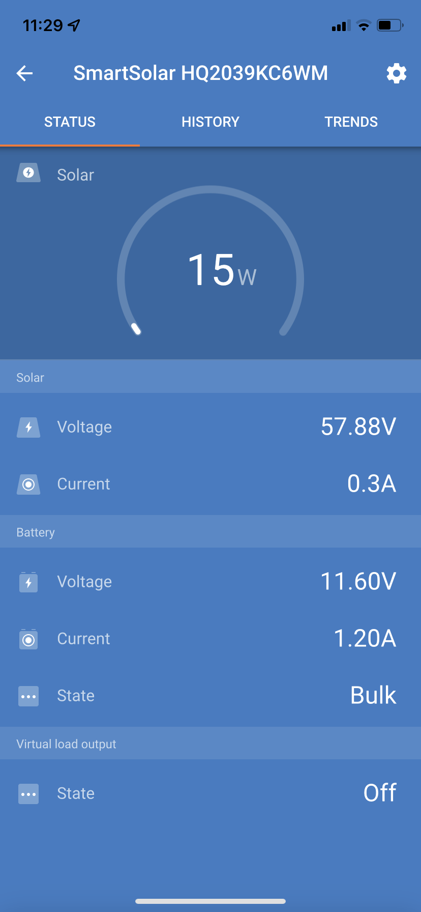
My controller shows it’s charging but the battery percentage is not going up. What’s happening?
Two likely causes. First, the controller may be in float mode, delivering only milliamps of maintenance current to an already-full battery. The display shows charging but meaningful current is not flowing. Check whether the charging current readout on the controller is above 0.5A. If it is in decimals, it is in float. Second, if the battery percentage display is on the inverter, inverter battery percentage readings are often miscalibrated and do not reflect actual state of charge accurately, especially on LiFePO4 banks. Measure battery terminal voltage directly and cross-reference against your battery’s voltage-to-SoC table.
The system charged fine for months. Now it barely charges. Nothing changed.
Something did change; you may just not have seen it. The most common causes of gradual charging degradation in a previously working system are MC4 connector corrosion accumulating over rainy seasons, controller performance degrading from repeated thermal stress, or early-stage cell imbalance in the battery worsening cycle by cycle. Run Step 4 of the diagnostic sequence: measure Voc at the panel and at the MPPT input and compare them. A growing voltage gap between those two measurements over time is the signature of connector resistance increasing.
Can I add more panels to fix a charging problem?
In most cases, no, and it can make things worse. Adding panels increases string Voc, which can push the array into the controller’s overvoltage protection range if the controller is already running near its maximum input voltage. It also does nothing to fix a configuration error, BMS trip, or wiring fault. Diagnose the root cause first. If after diagnosis the conclusion is genuine under-sizing, consult the MPPT sizing worked example before expanding the array.
My battery reads 0V at the terminals. Is it dead?
Not necessarily. Zero volts at the battery terminals on a lithium battery almost always means the BMS has opened the protection circuit due to over-discharge. The cells may be intact. Follow the BMS reset procedure in your battery documentation. Some units require a brief low-current charge through a dedicated recovery port; others reset automatically after a rest period. If the battery recovers and holds voltage after reset, the cells are viable and the root cause was deep discharge. Address the inverter cutoff settings to prevent recurrence. If the battery resets and immediately drops back to zero or near-zero under any load, cell damage has occurred.
How do I know if my MPPT controller is the problem or the panel is actually faulty?
Disconnect the panel from the controller and measure its open circuit voltage with a multimeter in direct sunlight. Compare this to the rated Voc on the panel datasheet, adjusted for temperature. If measured Voc is within 5 to 10% of the expected value, the panel is producing correctly. The fault is downstream, in the wiring, the controller, or the battery. Panel faults that cause complete charging failure are rare and almost always accompanied by visible physical damage: cracked glass, delamination, burn marks, or water ingress through a damaged junction box.
Is it normal for charging to stop in the afternoon even when the sun is strong?
No, it is not normal, but it is common. Mid-afternoon charging cutoff in strong sun is the symptom pattern of a controller entering thermal shutdown. It is also the pattern of a BMS tripping due to the battery reaching its over-voltage protection threshold on a hot day, since thermal derating reduces BMS tolerance in some units. Check the controller temperature and battery terminal voltage at the point charging stops. If the controller is hot and the battery is below absorption voltage, it is thermal shutdown. If the battery is at or above absorption voltage, it may be a BMS OVP trip caused by an absorption voltage setting that is too high for the battery’s rated thresholds.
My installer says the panel is faulty. Should I believe them?
Ask them to show you the evidence. A genuinely faulty panel will show a measured Voc significantly below its rated value under identical irradiance conditions compared to a working panel in the same string. If your installer is diagnosing a panel fault without measuring Voc and comparing it to the datasheet, the diagnosis is not based on evidence. Panel failures do occur, but they are far less common than configuration errors, wiring faults, and BMS trips. A good installer rules out the cheaper and more common faults first.
I am Engr. Ubokobong Ekpenyong, a solar specialist and lithium battery systems engineer with over five years of hands-on experience designing, assembling, and commissioning off-grid solar and energy storage systems. My work focuses on lithium battery pack architecture, BMS configuration, and system reliability in off-grid and high-demand environments.
Contains information related to marketing campaigns of the user. These are shared with Google AdWords / Google Ads when the Google Ads and Google Analytics accounts are linked together.
90 days
__utma
ID used to identify users and sessions
2 years after last activity
__utmt
Used to monitor number of Google Analytics server requests
10 minutes
__utmb
Used to distinguish new sessions and visits. This cookie is set when the GA.js javascript library is loaded and there is no existing __utmb cookie. The cookie is updated every time data is sent to the Google Analytics server.
30 minutes after last activity
__utmc
Used only with old Urchin versions of Google Analytics and not with GA.js. Was used to distinguish between new sessions and visits at the end of a session.
End of session (browser)
__utmz
Contains information about the traffic source or campaign that directed user to the website. The cookie is set when the GA.js javascript is loaded and updated when data is sent to the Google Anaytics server
6 months after last activity
__utmv
Contains custom information set by the web developer via the _setCustomVar method in Google Analytics. This cookie is updated every time new data is sent to the Google Analytics server.
2 years after last activity
__utmx
Used to determine whether a user is included in an A / B or Multivariate test.
18 months
_ga
ID used to identify users
2 years
_gali
Used by Google Analytics to determine which links on a page are being clicked
30 seconds
_ga_
ID used to identify users
2 years
_gid
ID used to identify users for 24 hours after last activity
24 hours
_gat
Used to monitor number of Google Analytics server requests when using Google Tag Manager
1 minute
You can find more information in our Cookie Policy and .


: Prices, Types & How to Choose")

")


")