Smart BMS vs Standard BMS: Is Bluetooth and App Control Worth It?
Smart BMS vs Standard BMS: learn the real difference between smart and standard BMS for LiFePO4 solar batteries. Discover how CAN bus and RS485 communication improve SOC accuracy, inverter coordination, battery lifespan, fault diagnosis, and overall system performance.
When someone asks whether a smart BMS is worth the extra cost, they are usually thinking about the Bluetooth app. The ability to open a phone and see battery data in real time seems convenient but optional, the kind of feature you buy if you have money to spare and like monitoring dashboards.
This framing misses the point entirely.
Bluetooth and the app are the visible surface of a smart BMS. What matters is what is underneath: a digital communication layer that connects the BMS to the inverter and fundamentally changes how the entire system operates. The app is useful for installers and engineers. The inverter communication is essential for system performance.
This article makes the case for smart BMS selection at the engineering level, not the marketing level. We cover what the communication layer actually does, why a standard BMS produces SOC errors of 15 to 25% in LiFePO4 systems, how that error compounds into measurable battery wear over years of cycling, and what the app data actually tells you when something goes wrong. We also cover the communication protocol landscape so you can match a smart BMS to your specific inverter without guessing.
This article builds on the BMS foundations established in What Is a BMS? 7 Essential BMS Functions and the protection framework covered in our BMS protection article. If you are new to the cluster, start there.
What Actually Separates a Standard BMS from a Smart BMS
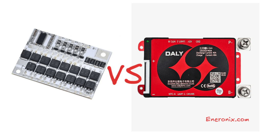
The distinction between standard and smart BMS is not primarily about build quality, cell count, or current rating. Two BMS units of identical current rating and identical cell count can be fundamentally different in their operational capability based on one thing: whether they have a digital communication interface.
A standard BMS is an island. It monitors the cells, protects the cells, and switches the MOSFETs. Everything it does is internal. It reports nothing to the outside world except the binary state of the pack circuit: connected or disconnected. The inverter, the MPPT controller, and any monitoring system are completely blind to what is happening inside the battery.
A smart BMS is a node in a network. It performs all the same protection functions internally, but it also transmits a continuous stream of real-time data to the inverter and to monitoring systems via a digital communication bus. It receives operating instructions in return. The inverter and the BMS operate as a coordinated system rather than as two independent devices that happen to be electrically connected.
This is the architectural difference. Everything else follows from it.
Smart BMS vs Standard BMS: Complete Feature Comparison
Feature
Standard BMS
Smart BMS
Cell voltage monitoring
Yes, per cell
Yes, per cell
Current monitoring
Yes
Yes
Temperature monitoring
Yes (basic, typically 1-2 sensors)
Yes (2-4 sensors, configurable)
Overvoltage / undervoltage protection
Yes
Yes
Overcurrent / short circuit protection
Yes
Yes
Passive cell balancing
Yes (usually)
Yes
Active cell balancing
Rarely
Yes (in active balancer variants)
CAN bus communication
No
Yes (on compatible units)
RS485 / Modbus communication
No
Yes (on compatible units)
CVL / CCL / DCL broadcasting
No
Yes
SOC estimation and reporting
Internal only, not broadcast
Calculated and broadcast to inverter
SOH tracking
No
Yes (on premium units)
Bluetooth app monitoring
No
Yes
Real-time cell voltage display
No (LED indicator only on some units)
Yes, per cell in real time via app
Fault history log
No
Yes, timestamped with cell data
Configurable protection thresholds
Fixed or limited
Fully configurable via app or PC software
Firmware update capability
No
Yes (OTA on some units)
Multi-pack parallel support
Limited / none
Yes (master-slave communication)
Remote monitoring integration
No
Yes (via RS485/CAN to cloud platforms)
Typical cost premium over standard
Baseline
+20 to 60% depending on features
KEY INSIGHT
The protection functions in rows 1 through 7 are present in both standard and smart BMS units. These functions work regardless of communication. What changes with a smart BMS is everything from row 8 onward: the ability to coordinate with the inverter in real time, report accurate SOC, log fault history, and allow configuration without hardware changes. For a solar system that operates autonomously every day for a decade, these are not optional extras. They are operational necessities.
Why Standard BMS Leaves Your Inverter Flying Blind
State of Charge estimation is where the performance gap between standard and smart BMS becomes most consequential, and it is most acute for LiFePO4 chemistry specifically.
How a Standard BMS Forces the Inverter to Guess
A standard BMS has no communication interface. The inverter cannot ask it what the battery’s SOC is. The only information the inverter has about the battery is the pack terminal voltage, which it reads through its own DC input measurement circuit.
For a lead-acid battery, voltage-based SOC estimation is reasonably reliable. Lead-acid voltage changes significantly and predictably with SOC across the full discharge range. A 48V lead-acid bank at 50.0V has a materially different SOC than one at 47.5V, and the inverter’s voltage-to-SOC lookup table maps these differences with reasonable accuracy.
For a LiFePO4 battery, this approach fails. The LiFePO4 discharge voltage curve is nearly flat from 90% down to 20% SOC, varying by only 50 to 100mV across that entire range. A 16S (48V nominal) LiFePO4 pack at 80% SOC and one at 40% SOC may both measure 52.0 to 52.8V at the pack terminals. The inverter cannot distinguish between them from voltage alone.
Inverter manufacturers know this problem and build chemistry-specific SOC tables into their firmware. But these tables are approximations calibrated to average cell behaviour. They are not calibrated to your specific cells, your specific aging state, your specific temperature, or the specific charge and discharge history of your pack. The error compounds over time as cells age and the gap between the firmware’s assumptions and reality grows wider.
Parameter
Standard BMS (No Communication)
Smart BMS (CAN / RS485 Communication)
Method used for SOC
Pack terminal voltage only
Coulomb counting + OCV calibration, broadcast via CAN/RS485
LiFePO4 flat curve problem
Severe. Voltage barely changes between 20% and 90% SOC. Inverter consistently misreads state.
Resolved. BMS coulomb counts charge flow precisely regardless of the flat voltage curve.
SOC error range (typical LiFePO4)
15-25% error common. Inverter may show 60% when pack is at 40%.
2-5% error. BMS-reported SOC is accurate throughout the cycle.
Effect on inverter generator trigger
Inverter switches to generator too early or too late due to incorrect SOC estimate.
Inverter triggers generator at the correct SOC. No wasted generator runtime or premature load shedding.
Effect on charge termination
Inverter may undercharge or overcharge relative to actual cell state.
Inverter uses BMS-reported CVL to terminate charging at the correct cell voltage, not a fixed pack voltage guess.
Effect on battery lifespan
Chronic over/under-utilisation accelerates aging. SOC floor violations common when inverter underestimates state.
Optimal utilisation. Correct SOC awareness prevents both chronically pushing cells to extremes and leaving significant capacity unused.
Fault detection capability
None. Inverter cannot distinguish between a pack at 30% SOC and a fault condition.
Full. BMS broadcasts fault codes and specific cell data. Inverter and monitoring system can respond to precise fault information.
This SOC mismatch between inverter display and actual battery state is one of the most commonly reported field problems in Nigerian solar installations. Our dedicated analysis: SOC drift: why your BMS and inverter disagree, documents the specific mechanisms and provides the diagnostic workflow to confirm whether SOC drift is occurring in a live system.
How SOC Error Translates Into Battery Wear
An inverter that consistently overestimates battery SOC allows the battery to be discharged deeper than intended. If the inverter thinks the battery is at 30% SOC when it is actually at 15%, it will not switch to generator backup until the battery is near empty. The cells are being routinely deep-discharged past the intended floor.
Conversely, an inverter that underestimates SOC switches to generator backup while 30 to 40% of battery capacity is still available. Generator runtime increases, solar self-consumption decreases, and the upper portion of the battery’s capacity is chronically underused.
Both errors are expensive. The first accelerates cell aging through chronic near-empty cycling. The second wastes generator fuel and solar generation. Neither error occurs with a smart BMS communicating accurate SOC directly to the inverter.
The financial cost of communication unreliability over a system’s lifetime is quantified in our article on the economics of battery communication reliability. The numbers make the case for smart BMS investment more clearly than any qualitative argument.
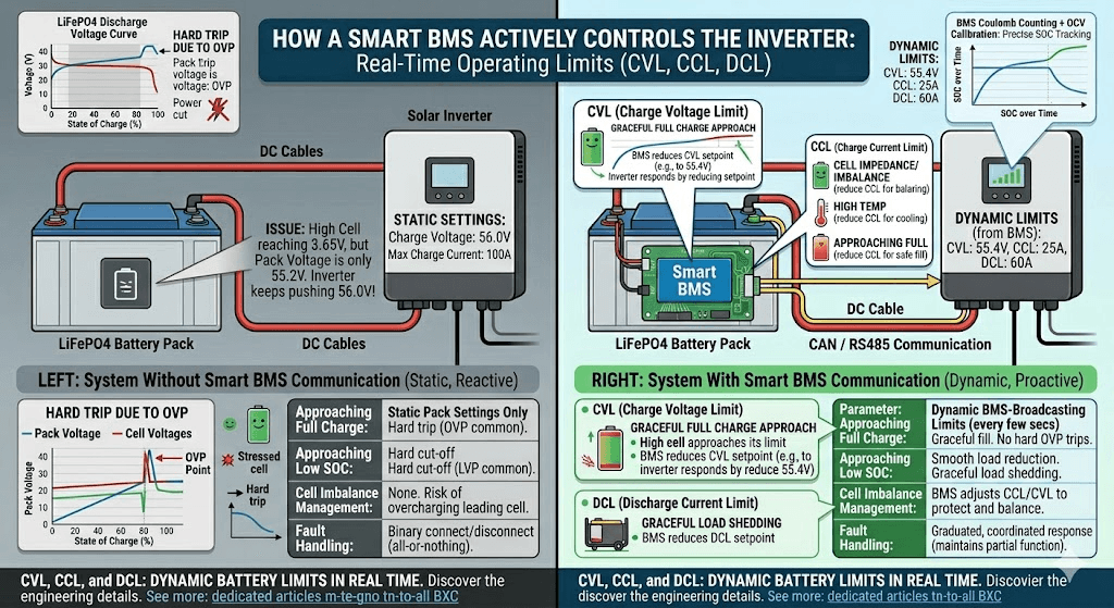
CVL, CCL, and DCL: How a Smart BMS Actively Controls the Inverter
Beyond SOC reporting, a smart BMS broadcasts three real-time operating limits to the inverter every few seconds. These are the Charge Voltage Limit (CVL), Charge Current Limit (CCL), and Discharge Current Limit (DCL). Together they allow the BMS to actively shape the inverter’s behaviour in real time, not just react to faults after the fact.
Charge Voltage Limit (CVL)
CVL is the maximum voltage the BMS is currently willing to accept from the charger. As the pack approaches full charge and individual cells approach their OVP threshold, the BMS reduces CVL progressively. The inverter responds by reducing its charge voltage setpoint.
This is critically important for LiFePO4 packs. In a 16S pack where cells are slightly imbalanced, the highest cell reaches its charge endpoint voltage before the pack as a whole reaches the configured charge voltage. Without CVL, the inverter continues pushing current until the pack terminal voltage reaches the inverter’s fixed setting, potentially overcharging the leading cell. With CVL, the BMS detects the leading cell approaching its limit and reduces CVL to slow the charge rate before the cell is stressed.
The result is a graceful approach to full charge rather than a hard trip. The battery fills more completely, cells are not stressed at the endpoint, and the BMS trips less frequently. Systems that experience frequent OVP trips during charging are almost always systems where CVL is not being communicated or not being respected by the inverter.
Charge Current Limit (CCL)
CCL is the maximum charge current the BMS will accept from the charger at any given moment. The BMS reduces CCL under several conditions:
As cells approach full charge (reducing current in the CV phase to prevent overvoltage at the cell level)
When cell or MOSFET temperatures exceed the soft-limit threshold (reducing current to reduce internal heating)
When a cell is significantly ahead of others in voltage (reducing current to allow balancing to catch up)
During recovery from a protection trip (gradual current ramp-up rather than immediate full-current reconnection)
An inverter receiving reduced CCL from the BMS scales back its charging current proportionally. This is a coordinated, graduated response to developing conditions, not a binary connect-disconnect. The system maintains partial functionality through edge conditions that would otherwise cause a hard trip and complete service interruption.
Discharge Current Limit (DCL)
DCL is the maximum discharge current the BMS will allow the inverter to draw. It is reduced under similar conditions to CCL: near the discharge floor, at elevated temperatures, and during recovery from protective events. When DCL reaches zero, the BMS is signalling the inverter to stop discharging entirely.
An inverter that respects DCL can reduce its output gradually as the battery approaches empty rather than experiencing a sudden hard disconnect. This is the difference between a graceful load shedding event and a hard power cut to all connected loads.
The full engineering detail of how CVL, CCL, and DCL interact with inverter firmware is covered in our dedicated article: CVL, CCL, and DCL: dynamic battery limits in real time. This is one of the most technically important articles in the Eneronix BMS cluster.
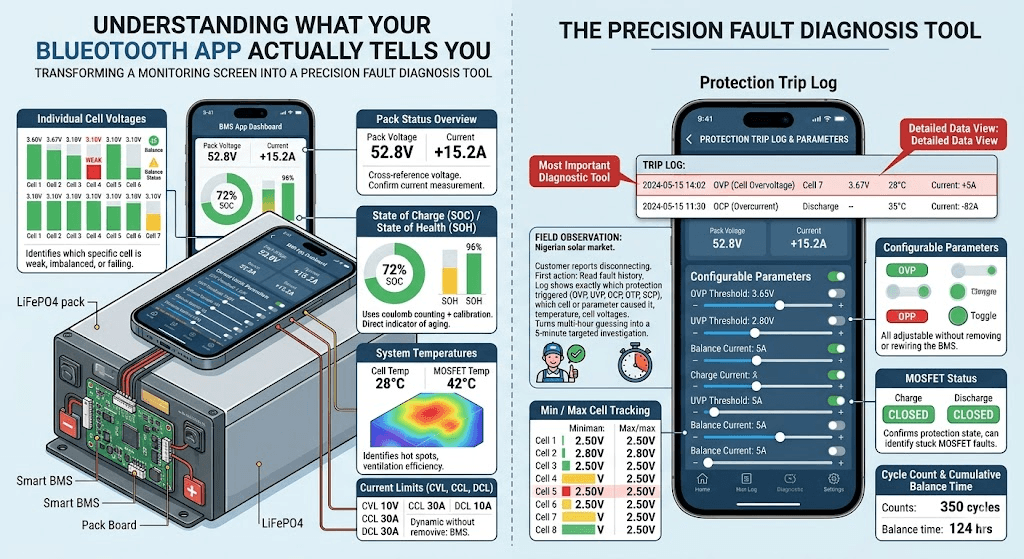
What the Bluetooth App Actually Tells You
The Bluetooth app on a smart BMS is not a cosmetic feature. It is the primary diagnostic interface for the battery pack. Understanding what data is available and what each item means transforms the app from a monitoring screen into a precision fault diagnosis tool.
Data Point
What It Tells You and Why It Matters
Individual cell voltages
Real-time voltage of every cell in the pack, typically updated every 100-500ms. Identifies which specific cell is weak, imbalanced, or failing.
Pack voltage
Total pack terminal voltage. Cross-reference against individual cell sum to detect wiring or measurement anomalies.
Charge / discharge current
Real-time current in amperes with direction indicator. Confirms the BMS is measuring current correctly and that load and charge sources are operating within spec.
State of Charge (SOC)
BMS-calculated SOC as a percentage. More accurate than inverter-reported SOC because it uses coulomb counting with periodic calibration.
State of Health (SOH)
On BMS units that track SOH: current capacity as a percentage of original rated capacity. Direct indicator of pack aging.
Temperature readings
Temperature at each thermistor location. Identifies hot spots, confirms whether enclosure ventilation is adequate, verifies thermistor placement and function.
Balance status
Which cells are currently being balanced, balance current magnitude (on active balancers), and cumulative balance time since last reset.
Protection trip log
Timestamped log of every protection event: OVP, UVP, OCP, OTP, SCP trips with cell data at the time of the event. The most important diagnostic tool for recurring fault investigation.
Cycle count
Total number of charge-discharge cycles completed. Useful for estimating remaining useful life.
Min / max cell tracking
Historical minimum and maximum voltage reached by each cell. Reveals which cells are routinely pushed to extremes even if no protection trip occurred.
MOSFET status
Whether charge and discharge MOSFETs are open or closed. Confirms protection state and can identify stuck MOSFET faults.
Configurable parameters
OVP, UVP, OCP, OTP thresholds, balance start threshold, balance current, communication protocol, SOC calibration. All adjustable without removing or rewiring the BMS.
FIELD OBSERVATION
In the Nigerian solar installation market, the single most valuable piece of data in the BMS app is the protection trip log. When a customer reports that their battery keeps disconnecting, the first action should be to open the BMS app and read the fault history. The log shows exactly which protection triggered (OVP, UVP, OCP, OTP, SCP), which cell or parameter caused it, and what temperature and cell voltages looked like at the time. This turns a multi-hour diagnostic guessing exercise into a 5-minute targeted investigation.
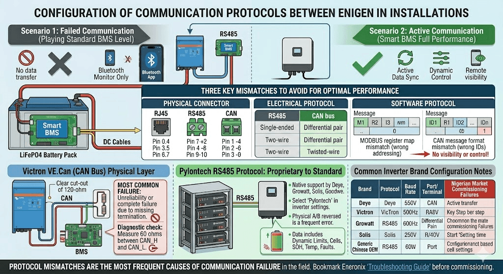
Matching Your Smart BMS to Your Inverter
A smart BMS that is not communicating with the inverter is performing at the level of a standard BMS. The Bluetooth app still works, but the inverter receives no data. This situation is more common than it should be in Nigerian installations, most often because the communication cable is not connected, or because the inverter is not configured to the correct battery protocol.
Getting the communication right requires matching three things: the physical connector, the electrical protocol layer, and the software protocol (the specific Modbus register map or CAN message format that the inverter expects).
Inverter / Battery Brand
Communication Protocol
Configuration Notes
Victron MultiPlus, Quattro, EasySolar
VE.Can (CAN bus at 500 kbps)
CAN bus via RJ45 connector. Must configure battery type as ‘Lithium’ and set the correct BMS protocol in VEConfigure or the Victron GX device.
Deye SUN-xK-SG series (hybrid)
RS485 Modbus with Deye/Solis protocol variant
RS485 via terminal block. Set battery type in inverter menu to match BMS brand (e.g., Daly, JK, or generic Lithium). Baud rate typically 9600.
Growatt SPF/SPH/MIN series
RS485 Modbus with Growatt protocol variant
RS485 via dedicated BMS communication port. Set battery type in Growatt parameter settings. Some Growatt models require specific Growatt-compatible BMS firmware.
Pylontech US2000/US3000 (built-in BMS)
RS485 with Pylontech protocol (also called PYLON protocol)
Pylontech batteries use their own proprietary RS485 protocol that many inverters support natively. Select ‘Pylontech’ or ‘PYLON’ in inverter battery settings.
Solis hybrid inverters
RS485 Modbus (Solis variant)
Similar to Deye. RS485 via terminal block. Set battery protocol to match BMS brand in Solis parameter configuration.
Goodwe hybrid inverters
CAN bus (GoodWe protocol)
CAN via RJ45. Select battery brand in GoodWe SEMS configuration or local display. GoodWe supports most major BMS brands natively.
Generic hybrid inverters (Chinese OEM)
RS485 Modbus (varies by brand)
Protocol varies widely. Confirm inverter’s supported BMS protocol list before specifying BMS. Mismatched protocols are one of the most common commissioning failures in the Nigerian market.
Protocol mismatches are one of the most frequent causes of BMS-to-inverter communication failure in the field. Our complete troubleshooting guide: BMS-to-inverter communication troubleshooting, covers every failure mode in the communication stack from physical wiring to protocol configuration. Bookmark it before commissioning any smart BMS installation.
CAN Bus Physical Layer: The Most Common Communication Failure
CAN bus is the preferred protocol for Victron systems and for most premium battery products. It is also the protocol most commonly installed incorrectly in the field.
CAN bus requires two 120-ohm termination resistors: one at each end of the CAN bus cable. In a system with only two devices (one BMS and one inverter), both the BMS and the inverter must have their termination resistors enabled. Many Victron devices have a DIP switch or jumper for CAN termination. Many BMS units have a termination jumper on the PCB. If either end is not terminated, CAN communication becomes unreliable at longer cable runs and completely fails in electrically noisy environments.
The specific physical layer requirements and the exact steps to diagnose and fix CAN termination problems are in our article: CAN bus physical layer: the 60-second fix for communication failures. This single article has resolved more field communication problems than any other resource in the Eneronix library.
The Pylontech RS485 Protocol: A Case Study in Proprietary Communication
Pylontech batteries use a proprietary RS485 protocol, widely referred to as the Pylontech or PYLON protocol. It has been adopted by so many inverter manufacturers that it has become a de facto standard for residential battery communication. Most hybrid inverter brands including Deye, Growatt, Solis, Goodwe, and Victron (via adapter) natively support the Pylontech protocol.
The Pylontech protocol transmits pack voltage, current, SOC, SOH, cell voltage range (highest and lowest cell), temperature range, fault status, and the three dynamic limits (CVL, CCL, DCL). It is a well-documented protocol that provides all the data an inverter needs to operate optimally with a Pylontech battery.
The key configuration step: the inverter must be set to ‘Pylontech’ or ‘PYLON’ in its battery communication settings, and the physical RS485 cable must connect the Pylontech battery’s RS485 port to the inverter’s BMS communication port. The RS485 A and B terminals must be correctly identified and not reversed.
What Happens When Communication Fails: The Silent Performance Degradation
A solar system where BMS communication has been lost does not usually fail immediately or dramatically. It continues to operate. Loads are powered. Charging happens. To a casual observer, the system appears functional.
What is actually happening is a systematic degradation of system performance that compounds over time:
The inverter reverts to voltage-based SOC estimation. For LiFePO4, the errors begin immediately. SOC display diverges from actual battery state.
The inverter stops respecting CVL, CCL, and DCL. It charges to its fixed voltage setpoint regardless of individual cell state. Cells that were being managed gracefully through the CV phase are now pushed to the OVP threshold, triggering hard trips that would not have occurred with active CVL reduction.
Generator runtime increases as the inverter incorrectly estimates the battery as empty earlier than it actually is, or fails to recognise when the battery is actually at risk of deep discharge.
Fault diagnosis becomes impossible. Without the BMS fault log communicating to the monitoring system, recurring protection trips go unrecorded and unnoticed until pack capacity has degraded to a point where the customer notices reduced runtime.
Balancing effectiveness reduces. Some smart BMS units use SOC information from the inverter to improve balancing algorithm decisions. Without the communication loop, balancing reverts to voltage-only triggering, which is less effective for LiFePO4.
Smart BMS Selection Guide: Which Specification for Which System
The following table provides a decision framework based on installation type and requirements. Use it as a specification tool when designing or specifying a new system.
Installation Scenario
BMS Specification
Engineering Rationale
Small DIY pack (under 100Ah), test bench or backup use, no inverter communication required
Standard BMS acceptable
Protection-only BMS sufficient. No inverter to communicate with and low cycling frequency means monitoring is not critical.
100-200Ah LiFePO4 pack, daily solar cycling, Deye/Growatt/Solis hybrid inverter
Smart BMS with RS485 required
Inverter needs BMS communication for accurate SOC. Without it the inverter operates blind on voltage estimates that are unreliable for LiFePO4.
200Ah+ LiFePO4 pack, daily deep cycling, off-grid or hybrid system
Smart BMS with active balancing + RS485 or CAN required
At this capacity and cycling frequency, both communication and active balancing are non-negotiable. JK BMS active balancer series is the practical choice for this specification in Nigeria.
Victron-based system (MultiPlus, Quattro, EasySolar)
Smart BMS with CAN bus (VE.Can compatible) required
Victron’s full integration capability requires CAN bus communication. RS485 BMS units work electrically but cannot take full advantage of Victron’s BMS integration features.
Commercial / industrial installation (10kWh+)
Smart BMS with CAN + SOH tracking + remote monitoring
At commercial scale, SOH tracking and remote monitoring via RS485/CAN to a cloud platform become operational requirements. Pylontech, BYD, and similar commercial units include this as standard.
The BMS decision is already made. Ensure the inverter is configured to communicate correctly with the specific battery brand’s protocol.
Any installation where post-commission fault diagnosis will be needed
Smart BMS always
The fault history log alone justifies the smart BMS cost premium in any professional installation. Diagnosing recurring BMS trips without per-cell timestamped data is guesswork.
For commissioning verification of the BMS-to-inverter communication link after installation, use the 10-stage checklist in our hybrid solar system commissioning checklist. Stage 5 of that checklist covers BMS communication verification specifically.
What to Look for When Evaluating Smart BMS Hardware
Not all devices marketed as smart BMS units deliver equivalent capability. The following parameters separate genuinely capable smart BMS hardware from units that use the smart label primarily as a marketing term.
Communication Interface Completeness
The BMS should support the specific protocol required by the inverter it will be connected to. CAN bus and RS485 are different physical and software layers. A BMS that supports RS485 Modbus but not CAN bus cannot communicate with a Victron MultiPlus without an external protocol converter. Verify the specific protocol variant supported, not just the physical interface type.
CVL, CCL, DCL Broadcasting
Confirm the BMS actively broadcasts all three dynamic limits, not just SOC and voltage. Some entry-level smart BMS units send read-only monitoring data (voltage, current, SOC) but do not implement the dynamic limit broadcasting that allows the inverter to adapt its behaviour. This is the difference between a BMS that provides data and one that actively participates in system control.
Fault History Log Depth
The fault log should store at least 20 to 50 timestamped events with full cell data at each event. Some budget smart BMS units store only the most recent fault or provide no timestamp, making it impossible to establish whether faults are occurring at predictable times (e.g., always during peak charging at midday, suggesting thermal root cause) or randomly.
Configuration Granularity
Every protection threshold should be individually configurable. A smart BMS that allows only preset chemistry profiles rather than individual threshold setting cannot be optimised for specific cell characteristics or adjusted as cells age.
Balancing Type and Configurability
For daily-cycling solar storage, the smart BMS should have active balancing with a configurable start threshold and configurable balancing current. A smart BMS with only passive balancing is incomplete for this application, regardless of how capable its communication interface is.
Temperature Sensor Count and Placement Flexibility
A minimum of two thermistors: one on the cell stack and one on the MOSFET board. Three or four thermistors provide better thermal mapping of large packs. Thermistor wire length matters for placement flexibility in large enclosures.
What Most Installers Get Wrong About Smart BMS Deployment
MISTAKE 1
Connecting the power cables but not the communication cable. This is the single most common smart BMS deployment error in Nigerian solar installations. The system powers up, appears to work, and the installer considers the job complete. The BMS is communicating nothing to the inverter. All the value of the smart BMS is sitting unused. Always verify communication establishment before signing off an installation.
MISTAKE 2
Connecting the communication cable but not configuring the inverter battery protocol setting. The cable is physically connected but the inverter is set to ‘Lead-Acid’ or ‘Generic Lithium’ or is looking for Pylontech when a JK BMS is installed. The inverter sees the cable but cannot parse the data. The fix is a single menu change in the inverter settings, but it requires knowing what protocol the BMS is transmitting and selecting the matching setting.
MISTAKE 3
Buying a smart BMS for the Bluetooth app without checking inverter protocol compatibility. The app works fine. The inverter communication does not. Specifying a BMS by Bluetooth app quality rather than by inverter protocol compatibility is backwards. Confirm protocol match first, app quality second.
MISTAKE 4
Not reading the BMS app after a protection trip. The fault log contains the complete diagnostic picture. Installers who reset BMS trips without reading the log are discarding the information they need to prevent the next trip. Make it standard practice to open the app and screenshot the fault log before every reset.
For the complete diagnostic workflow when the inverter shows incorrect battery percentage despite a smart BMS being installed, our article on inverter battery percentage wrong covers every root cause and the exact resolution steps for each.
Standard or Smart?
For any solar storage system operating with a hybrid or off-grid inverter in daily cycling service, the smart BMS is not the premium option. It is the minimum viable specification.
The standard BMS is appropriate only where all three of the following conditions apply simultaneously: the pack is small (under 100Ah), cycling frequency is low (weekly or less), and there is no inverter communication requirement (standalone or generator-only charging). Outside these conditions, the standard BMS is an undersized specification.
The cost differential between a standard and smart BMS for a 48V 16S pack is typically 15 to 40 USD. Against the 5 to 10 year lifecycle of a solar battery installation worth 800 to 3,000 USD in battery cost alone, this differential is not a meaningful financial consideration. The operational benefits of accurate SOC reporting, dynamic limit coordination, fault history logging, and remote configuration access return their cost within the first months of operation.
The question of whether Bluetooth and app control is worth it has a simple answer: the Bluetooth and app are worth something. The inverter communication layer is worth a great deal. The combination of both, in a single unit, at a small price premium over a protection-only BMS, is a straightforward engineering and financial decision.
To understand how to monitor the full solar system including BMS data through a cloud platform after installing a smart BMS, our guide on how to monitor a hybrid solar system remotely covers Victron VRM, Growatt ShineServer, and Deye SolarmanPro integration in detail.
Frequently Asked Questions
What is the difference between a smart BMS and a standard BMS?
A standard BMS performs protection functions only: overvoltage, undervoltage, overcurrent, short circuit, and temperature protection. It does this internally and communicates nothing to the inverter or monitoring system beyond an on/off switch behavior. A smart BMS does all of this plus communicates real-time cell data to the inverter via CAN bus or RS485, broadcasts dynamic operating limits (CVL, CCL, DCL), provides Bluetooth app access for monitoring and configuration, stores a timestamped fault history log, and allows all protection thresholds to be configured without hardware changes.
Is a smart BMS worth the extra cost?
For any solar storage system cycling daily with a hybrid or off-grid inverter, yes. The inverter relies on BMS-reported SOC to make correct charge and discharge decisions. Without BMS communication, the inverter uses pack terminal voltage to estimate SOC, which is unreliable for LiFePO4. The resulting SOC errors lead to inefficient battery utilisation, premature load shedding, and accelerated cell aging from operating outside the intended SOC window. The cost difference between a standard and smart BMS is typically 15 to 40 USD. The value of correct SOC reporting over 5 years of daily cycling is many times that amount.
What does Bluetooth app control actually do on a smart BMS?
The Bluetooth app provides real-time access to individual cell voltages, pack voltage, charge and discharge current, State of Charge, temperatures at each thermistor, balance activity status, MOSFET open/closed status, protection trip history with timestamps and cell data at the time of each event, cycle count, and all configurable parameters including OVP, UVP, OCP, OTP thresholds and balance settings. It turns a sealed battery box into a transparent, fully inspectable system without requiring any physical intervention.
Do I need a smart BMS if I have a Pylontech battery?
Pylontech batteries (US2000C, US3000C, and similar) have an integrated smart BMS built into the unit. They communicate via RS485 using the Pylontech protocol. You do not need an external smart BMS. What you do need is to configure your inverter correctly to recognise the Pylontech protocol, connect the RS485 communication cable (not just the power cables), and verify in the inverter interface that it is receiving BMS data. Many Nigerian installations use Pylontech batteries but leave the RS485 communication cable disconnected, losing all the benefits of the integrated smart BMS.
What is CVL, CCL, and DCL in a smart BMS?
CVL is the Charge Voltage Limit: the maximum voltage the BMS is currently willing to accept from the charger. As cells approach full, the BMS reduces CVL to signal the inverter to taper off charging. CCL is the Charge Current Limit: the maximum current the BMS will accept from the charger. Reduced when cells are near full, when temperatures are high, or when a fault condition is developing.
DCL is the Discharge Current Limit: the maximum current the BMS will allow the inverter to draw. Reduced when cells are near empty or when temperatures are elevated. Together, CVL, CCL, and DCL allow the inverter to adapt its behavior continuously to the actual condition of the battery rather than operating from fixed parameters set at installation.
Can a smart BMS work without being connected to the inverter?
Yes. A smart BMS performs all its protection functions independently of the inverter communication. If the communication cable is disconnected, the BMS still protects the cells via its MOSFET switching. What is lost is the ability to broadcast CVL, CCL, and DCL to the inverter, meaning the inverter operates on its own fixed voltage parameters rather than real-time BMS data. The Bluetooth monitoring also continues to work independently of inverter communication.
What communication protocol does a JK BMS use?
The JK BMS (Jikong) supports RS485 with a Modbus-based protocol and also has a UART interface for Bluetooth communication. The RS485 output is compatible with most Chinese hybrid inverter brands including Deye, Growatt, and Solis. Some JK BMS variants also support CAN bus. The specific protocol variant must be matched to the inverter’s expected battery communication format in both the BMS and inverter configuration.
How do I know if my BMS is communicating correctly with my inverter?
The definitive check is in the inverter’s battery status display. If the inverter shows the battery SOC as a percentage (not a voltage), is displaying a battery current reading that matches the BMS app reading, and is showing battery temperature, then communication is established and working. If the inverter shows only voltage or shows dashes in the SOC field, communication is either not connected, not configured, or has a protocol mismatch.
What is the best smart BMS for a 48V LiFePO4 solar system in Nigeria?
For a DIY 48V (16S) LiFePO4 pack in the 100 to 300Ah range, the JK BMS active balancer series (specifically the B2A8S20P or B2A24S20P depending on cell count) is the most widely deployed and field-proven choice in the Nigerian market. It combines active balancing up to 2A, full RS485 communication compatible with Deye, Growatt, and Solis inverters, Bluetooth app monitoring, configurable protection thresholds, a timestamped fault log, and a current rating of up to 200A continuous at a price point that represents good value for its feature set. For Victron-based systems, a CAN-compatible BMS or a Pylontech battery with native Victron integration is the better choice.
What happens if you use a standard BMS with a hybrid inverter?
The inverter powers the load and charges the battery correctly at the electrical level. However, the inverter cannot receive real-time SOC, CCL, CVL, or DCL data from the battery. It defaults to using pack terminal voltage for SOC estimation, which for LiFePO4 introduces errors of 15 to 25%. The inverter may switch to generator or grid backup earlier than necessary, may not terminate charging at the correct point, and cannot respond to developing fault conditions with proportional current reduction before a hard BMS trip becomes necessary. Over years of daily cycling, these deficiencies compound into measurable capacity loss and reduced battery lifespan.
I am Engr. Ubokobong Ekpenyong, a solar specialist and lithium battery systems engineer with over five years of hands-on experience designing, assembling, and commissioning off-grid solar and energy storage systems. My work focuses on lithium battery pack architecture, BMS configuration, and system reliability in off-grid and high-demand environments.
Contains information related to marketing campaigns of the user. These are shared with Google AdWords / Google Ads when the Google Ads and Google Analytics accounts are linked together.
90 days
__utma
ID used to identify users and sessions
2 years after last activity
__utmt
Used to monitor number of Google Analytics server requests
10 minutes
__utmb
Used to distinguish new sessions and visits. This cookie is set when the GA.js javascript library is loaded and there is no existing __utmb cookie. The cookie is updated every time data is sent to the Google Analytics server.
30 minutes after last activity
__utmc
Used only with old Urchin versions of Google Analytics and not with GA.js. Was used to distinguish between new sessions and visits at the end of a session.
End of session (browser)
__utmz
Contains information about the traffic source or campaign that directed user to the website. The cookie is set when the GA.js javascript is loaded and updated when data is sent to the Google Anaytics server
6 months after last activity
__utmv
Contains custom information set by the web developer via the _setCustomVar method in Google Analytics. This cookie is updated every time new data is sent to the Google Analytics server.
2 years after last activity
__utmx
Used to determine whether a user is included in an A / B or Multivariate test.
18 months
_ga
ID used to identify users
2 years
_gali
Used by Google Analytics to determine which links on a page are being clicked
30 seconds
_ga_
ID used to identify users
2 years
_gid
ID used to identify users for 24 hours after last activity
24 hours
_gat
Used to monitor number of Google Analytics server requests when using Google Tag Manager
1 minute
You can find more information in our Cookie Policy and .