Hybrid Solar System Wiring Guide: DC Side, Battery, AC Output and Protection Explained
Hybrid solar system wiring explained: DC array, battery cables, AC output, protection devices, earthing, and the wiring mistakes that cause inverter failure in Nigeria.
Most hybrid solar system fires in Nigeria are not caused by defective components.
They are caused by undersized battery cables. Missing fuses. Unearthed array frames. Inverter output wired onto the same busbar as the NEPA supply. Wiring errors that take two minutes to make and years to trace back after the damage is done.
This guide explains hybrid solar system wiring in detail, including DC array connections, battery cable sizing, AC distribution, and protection design for Nigerian installations. It covers every wiring segment, every protection device, every failure mode, and the exact sequence to follow at installation.
Who this guide is for:
Solar installers preparing for a hybrid system installation. System engineers verifying a completed design. Advanced system owners who want to understand what is inside the plant room before handing over N3 million to N12 million.
When NOT to DIY:
The battery DC segment of a hybrid system carries currents between 70A and 230A at 48V. A short circuit in this segment without a correctly rated fuse in the right position releases enough energy to weld terminals, ignite cable insulation, and start a fire in under two seconds. Battery DC wiring should not be attempted without proper crimping tools, calibrated torque specifications, and experience with high-current DC systems.
Hybrid Solar System Wiring (Quick Answer)
Hybrid solar system wiring refers to the electrical connections between all components of a hybrid solar system: the solar array, the hybrid inverter, the battery bank, the grid connection, and the load distribution board. It covers three distinct wiring segments operating at three different voltage levels, each with its own cable specification, protection requirements, and failure modes.
The three wiring segments:
Segment
Voltage
Primary Risk
DC array (panels to inverter MPPT input)
100V to 500V DC
Arc faults, insulation failure
Battery DC (battery to inverter DC bus)
48V DC (high current)
Fire from short circuit
AC output (inverter to distribution board)
230V AC
Shock, back-feed electrocution
Energy flow in plain language:
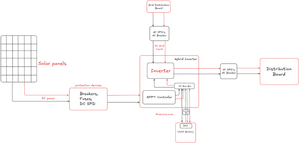
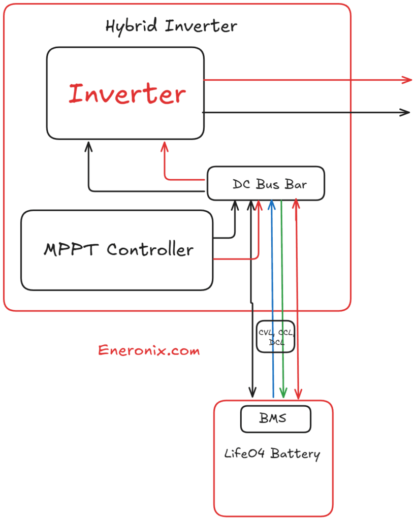
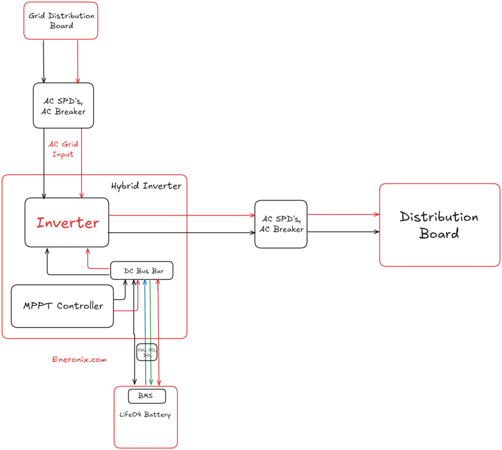
Solar panels generate DC electricity. That DC flows through the array isolator into the inverter’s built-in MPPT charge controller. The MPPT charges the battery bank and simultaneously powers loads. The battery communicates its state to the inverter every second via a BMS communication cable. The inverter converts DC to 230V AC and delivers it to a dedicated solar distribution board. Your loads connect to that board. The grid connects to a separate AC input port on the inverter with its own isolation.
That is the complete energy path. Every wire in the system belongs to one of those three segments.
Hybrid Solar System Wiring Diagram Explained (Step by Step for Nigeria)
A wiring diagram shows where every conductor starts and ends and what protection device sits between the two points. This walkthrough describes the complete hybrid system wiring path in the sequence power actually flows.
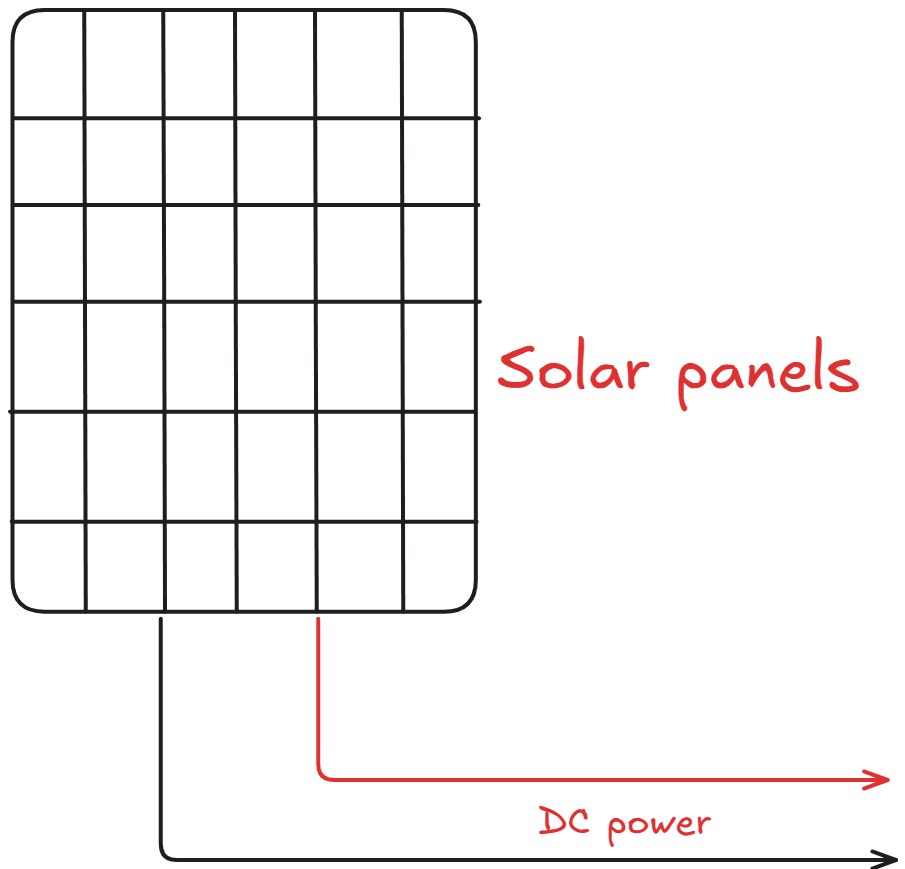
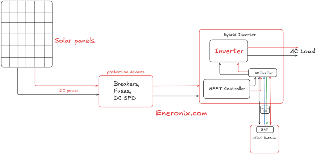
Step 1: Solar panels generate DC power.
Each panel produces DC electricity at its maximum power point voltage. Panels are connected in series to form strings. A string of four 500Wp panels produces approximately 150V to 200V DC at operating conditions. The string positive and negative conductors run in 4mm2 solar PV cable from the roof to the plant room.
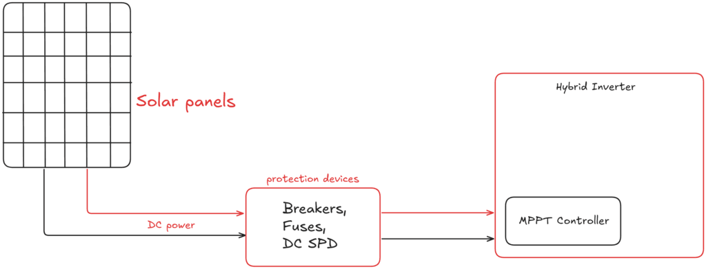
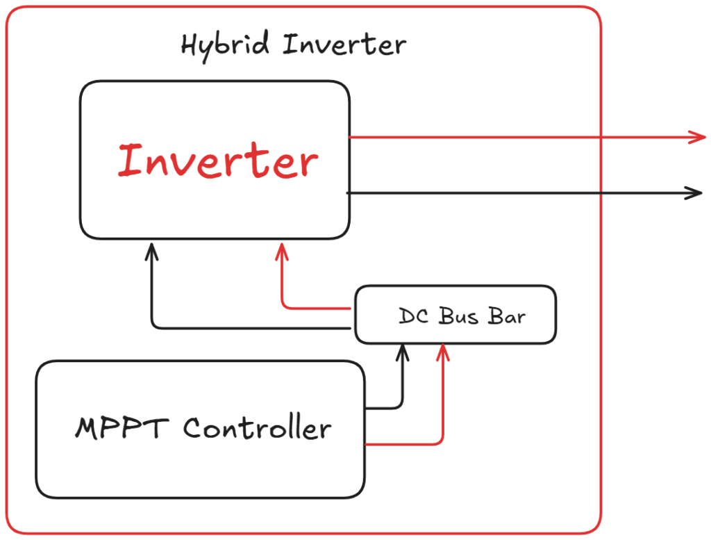
Step 2: DC flows through protection to the inverter MPPT input.
Before the string reaches the inverter, it passes through a DC array isolator (allows safe disconnection for maintenance) and a DC surge protection device (SPD) rated for the string voltage. If multiple strings are combined, each string has its own fuse in a combiner box before the combined output reaches the inverter.
Step 3: The MPPT charges the battery and powers loads simultaneously.
The MPPT stage extracts maximum available power from the PV array and feeds the DC bus. A higher-level control system uses BMS signals (CVL, CCL, DCL) to regulate battery charging and discharging, while the inverter simultaneously converts DC bus power to AC for loads. If necessary, the controller limits PV power by adjusting the MPPT operating point.
Step 4: The battery communicates its state to the inverter via BMS.
A communication cable (CAN bus or RS485) runs from the battery’s BMS port to the inverter’s communication port. This cable is not a power cable. It carries digital signals telling the inverter the exact cell voltages, temperatures, SOC, and current limits at every moment. Without this cable, the inverter manages the battery blind.
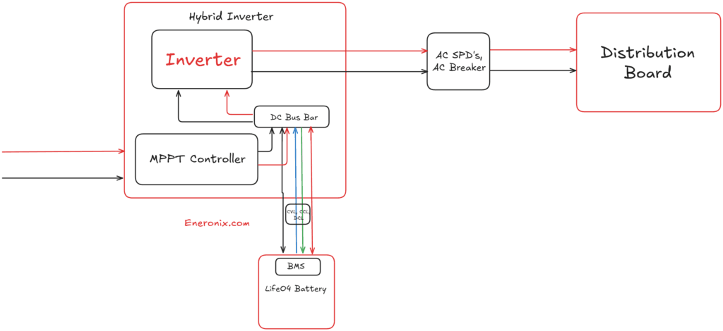
Step 5: The inverter converts DC to 230V AC for loads.
The inverter’s bidirectional AC-DC stage converts the DC bus voltage to a 230V 50Hz AC waveform. During island mode (NEPA absent), the inverter generates this waveform independently. During grid-connected mode, it synchronises to the grid waveform.
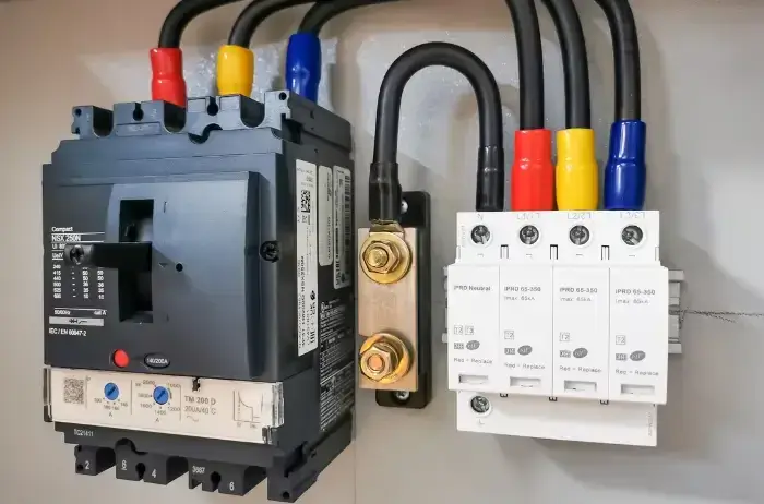
Step 6: AC flows through protection to the solar distribution board.
The inverter AC output connects via a main RCBO to a dedicated solar DB. From the solar DB, individual RCBOs protect each output circuit (lighting circuit, power circuit, refrigeration circuit). Loads connect to these circuits.
Step 7: The grid connects to the inverter AC input with its own isolation.
The NEPA supply enters through the property’s existing meter and main isolator. A separate grid input cable runs from the NEPA distribution board to the inverter’s AC input port with its own MCB. An AC SPD on this input protects the inverter from voltage transients coming in from the NEPA line.
Where each protection device sits:
DC SPD: between array isolator and inverter MPPT input
ANL fuse: within 300mm of battery positive terminal
Battery isolator: between battery positive terminal and ANL fuse
Main RCBO: at inverter AC output
Individual RCBOs: at solar DB for each circuit
AC SPD: at grid input to inverter
Grid input MCB: at NEPA DB before cable run to inverter
DC Array Wiring (Panels to Inverter MPPT Input)
Solar PV Cable Specification
The cables running from your solar panels to the inverter are not standard electrical cables. They are a specific product category with requirements that standard cables cannot meet.
Solar PV cable must be:
Rated 1,000V DC minimum: Standard electrical cables are rated for AC voltages. DC fault voltages are higher than AC equivalents at the same nominal rating. A 1,000V DC-rated cable has a different insulation specification from a 1,000V AC-rated cable.
Double insulated: Two independent layers of insulation provide redundancy. If the outer sheath is damaged, the inner insulation maintains isolation. In a DC circuit, a single insulation failure between two conductors creates a short circuit that does not self-extinguish at zero crossing the way an AC fault does.
UV-resistant outer sheath: Standard NYM or flex cable sheaths degrade and crack within 2 to 3 years of direct sunlight exposure in Nigerian conditions. Cracked sheathing on a rooftop string cable is a slow-burning ignition risk.
Temperature-rated to 90°C to 120°C: Panel surfaces and roof substrate in Nigerian dry season reach 70°C or above. Standard cable rated to 70°C is operating at its thermal limit before any load current is added.
Using standard domestic flex or NYM cable for string runs is one of the most common fire risks in Nigerian solar installations. The insulation fails silently over two to three years. By the time the arc fault is detectable, the cable sheath is already charred.
MC4 Connectors
All panel-to-panel and panel-to-cable connections use MC4 connectors. A genuine MC4 connector is IP67-rated, UV-resistant, rated for 1,000V DC, and designed to mate with the specific contact geometry of the male-female pair.
The Nigerian solar market has a documented problem with counterfeit MC4 connectors. These look identical to genuine MC4 connectors on the outside. Inside, the contact material is lower-grade, the locking mechanism is weaker, and the UV resistance of the housing is inferior. Within two to three years, the contacts oxidise, connection resistance increases, and the connector heats under load. A hot MC4 connector in a string carrying 13A is a localised arc fault waiting to happen.
Verify MC4 brand before purchase. Genuine Staubli MC4 connectors are the industry standard. Approved equivalents include Amphenol, Renhe, and specific OEM brands supplied by Tier 1 panel manufacturers. Reject any connector that does not carry a visible brand mark and 1,000V DC rating print on the housing.
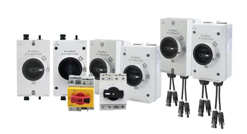
DC Array Isolator
A DC array isolator is a manual disconnect switch installed between the solar string output and the inverter MPPT input. It allows the string to be de-energised before any work on the wiring between the panels and the inverter.
Solar panels cannot be switched off. As long as sunlight hits the cells, the string is generating voltage. The only way to make the wiring safe for maintenance is to open the isolator. Without one, every maintenance intervention on the DC array wiring is a live-working event.
The isolator must be rated for the maximum string voltage (Voc at minimum temperature) and the string short-circuit current (Isc). For a four-panel string with Voc of 203V at 15°C and Isc of 13.5A, the isolator must be rated for at least 250V DC and 15A DC. Note: AC-rated isolators cannot be used on DC circuits. DC arcs do not self-extinguish at zero crossing. A DC-rated isolator has a wider contact gap designed to interrupt DC arc current.
For a complete guide to series vs parallel string configuration and its effect on array voltage and current, read our article on series vs parallel solar panels.
DC SPD at MPPT Input
image source: letopv
The DC surge protection device (SPD) at the inverter MPPT input is the most frequently omitted protection device in Nigerian hybrid system installations. It is also the one whose absence has the most expensive consequences.
In Nigerian harmattan season, electrostatic discharge events generate voltage transients on exposed conductors. A rooftop solar array is a long conductor spanning 10 to 30 metres of roof area. A transient event above the inverter’s MPPT maximum input voltage destroys the MPPT stage permanently. The inverter body continues to function as an inverter-charger but solar input is dead. MPPT replacement on a hybrid inverter typically costs 40 to 60% of the inverter’s original price.
The DC SPD must be:
Voltage-rated above the maximum string Voc (Voc at minimum temperature x 1.2 minimum)
Current-rated for the available short-circuit current at the installation point
Connected with the earth lead as short as possible and absolutely no longer than 0.5 metres to the earthing busbar
Installed at the inverter DC input, not at the array (surges must be diverted before they reach the inverter)
Battery DC Wiring (Battery to Inverter) + Cable Size Guide
This is the segment responsible for the most dangerous failures in Nigerian hybrid installations. The battery-to-inverter cables carry the highest current in the entire system. At 48V, a 5kVA inverter draws up to 111A from the battery during peak discharge. A 10kVA inverter draws up to 230A. These are not household electrical currents. They are welding-grade currents.
Battery Cable Size for Inverter
Battery DC cables must be:
Flexible single-core welding cable or dedicated battery cable: Rigid cable is not appropriate for battery connections because vibration and thermal expansion cycles will crack the insulation at termination points over time. Flexible cable with fine-strand conductors handles thermal cycling without fatigue.
Tinned copper conductors: Tinning prevents oxidation at termination points. In Lagos and Port Harcourt where humidity is consistently above 70%, bare copper terminals develop a resistance layer of copper oxide within 2 to 3 years. That layer creates resistive heating at the joint. On a cable carrying 111A, a 0.01-ohm joint resistance dissipates 123W of heat at that point. Tinned terminals maintain low-resistance contact throughout the system’s life.
Correctly rated insulation: 60V DC minimum rating. Temperature rating to 90°C.
Battery Cable Sizing Quick-Reference Table
System
Inverter Size
Max Battery Current
Up to 2m Run
Up to 5m Run
3kVA 48V
3,000W
70A
25mm2
35mm2
5kVA 48V
5,000W
115A
35mm2
50mm2
8kVA 48V
8,000W
185A
50mm2
70mm2
10kVA 48V
10,000W
230A
70mm2
95mm2
Keep the battery-to-inverter run under 2 metres wherever the plant room layout allows. Every extra metre of cable is a voltage drop (see our article on voltage drop in solar systems) and a resistive heat source under load.
An ANL fuse (or Class T fuse) must be installed on the positive battery cable within 300mm of the battery positive terminal.
The 300mm rule is not arbitrary. Its purpose is to minimise the length of unfused cable between the battery terminal and the fuse. The section of positive cable between the battery terminal and the fuse is not protected by the fuse. If a short circuit or insulation failure occurs in that section, the battery can deliver its full short-circuit current into the fault indefinitely.
A fully charged 48V 200Ah LiFePO4 battery can deliver 2,000A to 4,000A of short-circuit current for the milliseconds before the BMS disconnects. In 300mm of 35mm2 cable, that current produces enough heat to ignite the cable insulation immediately.
Some Nigerian installers run the positive cable 1 to 2 metres from the battery before installing the fuse at the inverter input terminals. Every centimetre of unfused positive cable between the battery and the fuse is a potential ignition source.
ANL Fuse Sizing
The ANL fuse rating must be:
Above the maximum continuous discharge current of the system (to avoid nuisance blowing under surge loads)
Below the cable’s continuous current rating (so the fuse clears before the cable is damaged)
For a 5kVA 48V system with maximum continuous discharge of 115A on 35mm2 cable rated for 140A continuous:
ANL fuse rating = 1.5 to 1.8 x maximum continuous current = 173A to 207A. Select 200A ANL.
The fuse clears a dead short (4,000A) in microseconds. It does not blow during a 115A normal discharge or a 230A surge event. It blows if the cable is shorted.
BMS Communication Cable
The BMS communication cable runs from the battery’s BMS port to the inverter’s CAN or RS485 communication port. This cable carries digital signals, not power.
Use only the manufacturer-supplied communication cable or an exact specification equivalent. CAN bus cables have specific impedance, capacitance, and termination requirements. RS485 cables have specific characteristic impedance requirements. Substituting arbitrary two-core or telephone cable introduces impedance mismatch that causes communication errors, BMS signal dropouts, and ultimately blind battery management.
Keep the communication cable away from DC power cables wherever possible. Running a signal cable alongside a 111A DC cable introduces electromagnetic interference that can corrupt the BMS signal. Separate power and signal cables by at least 100mm or route them in separate conduits.
Use twin-earth cable in conduit for the inverter-to-DB run. Do not use single-core conductors in open trunking for this segment. The inverter AC output is a live source whether NEPA is present or not. If the conduit is damaged and the cable is exposed, the 230V AC output of the inverter in island mode is a direct electrocution hazard.
For the full AC wiring methodology including cable sizing under load and conduit selection, read our AC wiring guide.
The Dedicated DB Rule
The inverter AC output must connect to a dedicated solar distribution board. Not the same board as the NEPA supply. Not the same board as the generator output.
Here is why this rule is non-negotiable.
When the inverter is in island mode, it is generating 230V AC on its output terminals. If that output is bussed onto the same distribution board as the NEPA supply, the NEPA conductors leaving the DB are now energised by the inverter. A NEPA lineman working on the feeder cable to your property believes that cable is dead because NEPA has failed and the street is dark. Your inverter has energised that cable through your meter, through your main isolator, through your DB, and out onto the network.
This is the mechanism behind electrician electrocution events related to solar systems. It is not theoretical. It is documented. And it is prevented by one design rule: the inverter output goes to its own DB, and that DB has no physical connection to the NEPA supply busbar.
The correct arrangement for a Nigerian home with NEPA, generator, and hybrid inverter:
NEPA supply: its own DB with its own circuits
Generator output: its own transfer switch and connection point
Inverter output: its own solar DB with its own circuits for essential loads
Critical loads wired to solar DB permanently
Non-essential loads wired to NEPA DB
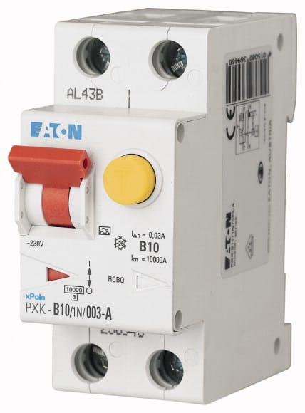
Individual RCBOs Per Circuit
Every output circuit from the solar DB must have its own RCBO. Not a shared MCB for multiple circuits.
An RCBO combines overcurrent protection (the MCB function) and earth fault protection (the RCD function) in a single device. It trips on two conditions: the circuit current exceeds the rated value, or current is leaking to earth through a fault.
Size each RCBO based on the circuit’s cable cross-section and maximum load:
Lighting circuit (1.5mm2 cable, maximum 800W load): 6A RCBO
Power socket circuit (2.5mm2 cable, maximum 3,000W load): 16A RCBO
Individual RCBOs mean a fault on one circuit trips only that circuit. The rest of the system keeps running. The kitchen fridge stays on when the bedroom wiring develops a fault. That resilience is the entire reason for individual protection.
Protection Coordination
Protection coordination means every protection device is sized so that a fault causes the nearest upstream device to operate, not a device several levels up in the hierarchy.
If a bedroom circuit develops a short circuit and the main RCBO at the inverter output trips instead of the bedroom RCBO, the entire solar DB loses power. All protected loads go dark. The fault cleared correctly in terms of safety, but it cleared at the wrong level. Correct coordination means the bedroom RCBO trips. The solar DB stays live. Everything else continues.
Most Nigerian hybrid system installations have no proper earthing. They rely on the NEPA supply earth, which is frequently absent from Nigerian residential connections, corroded at the meter point, or shared between multiple buildings on a single deteriorated electrode.
This matters because a hybrid inverter in island mode is the voltage reference for the home. The system neutral floats relative to true earth unless the inverter is independently earthed. A floating neutral in a hybrid system causes dangerous touch voltages on exposed metal parts, nuisance RCBO tripping when the system switches to island mode, and incorrect operation of earth fault protection.
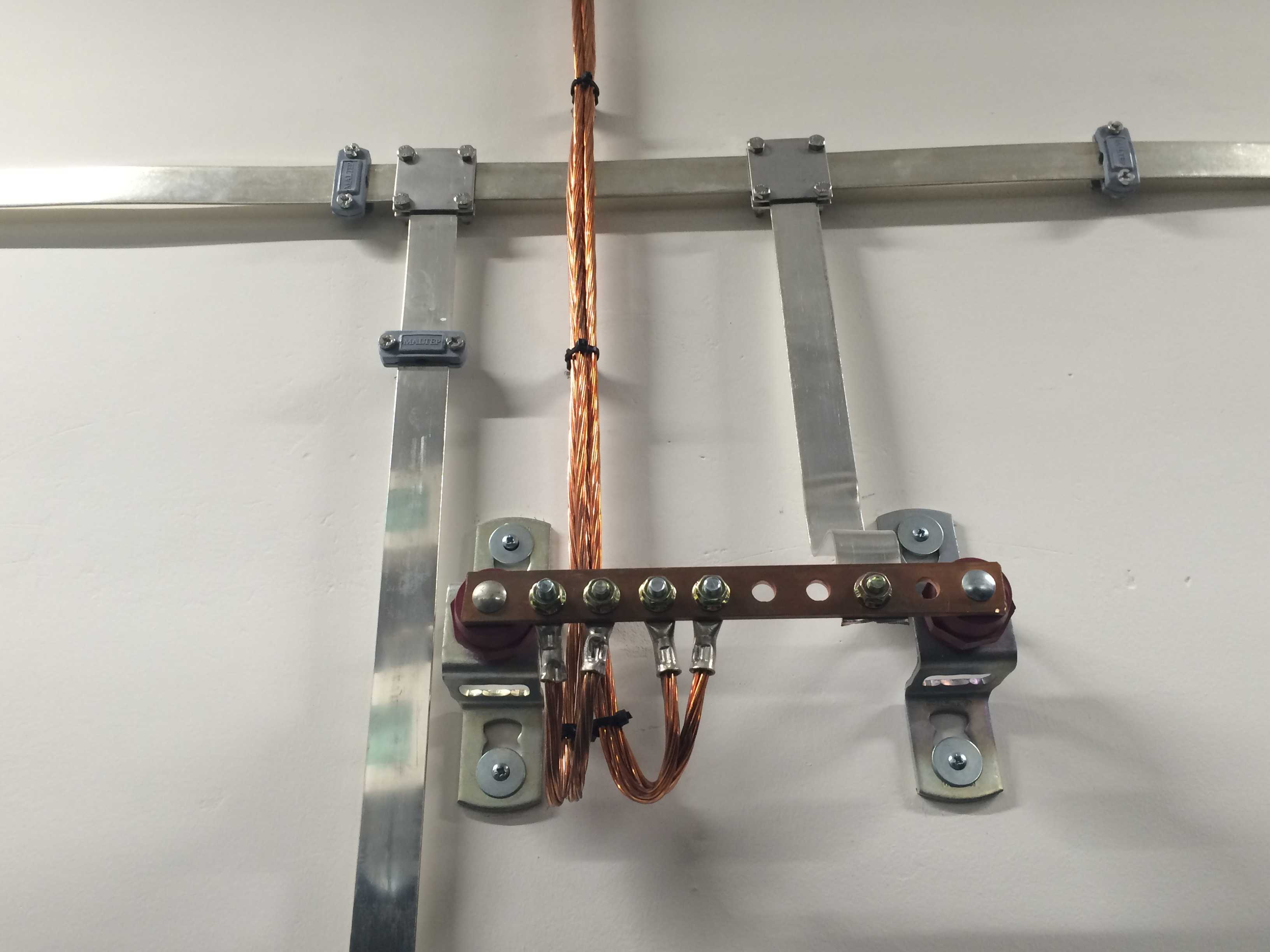
The Three Earthing Connections Required
1. Inverter chassis earth terminal: Every hybrid inverter has a PE (protective earth) terminal on the chassis. This must connect via a green-yellow earth conductor (minimum 6mm2 for a 5kVA system) directly to the earthing electrode. Do not rely on the NEPA supply earth for this connection. In island mode, the NEPA supply is disconnected. If the inverter earth depends on the NEPA supply path, the earth is lost at the exact moment island mode is active.
2. Solar array frame bonding: All solar panel frames and aluminium mounting rails must be bonded together with a continuous earth conductor and connected to the same earthing electrode as the inverter. An unearthed solar array frame accumulates voltage from capacitive coupling between the high-voltage DC string and the frame. In harmattan, an unearthed array frame can develop 50V to 150V touch potential. A maintenance person touching the frame and a grounded surface simultaneously receives that voltage across their body.
3. Battery enclosure bonding: The battery enclosure or rack must also be bonded to the same earthing electrode. Any fault between a battery cell and the enclosure in an unearthed battery rack results in the entire enclosure floating at battery potential.
Earthing Electrode in Nigerian Conditions
A copper-clad steel ground rod of minimum 1.2 metres driven vertically to below the permanent moisture level of the soil is the standard earthing electrode for Nigerian residential installations.
In Lagos and Port Harcourt, the water table is close to the surface. A 1.2-metre rod reliably reaches permanently moist soil in most locations. Earth resistance below 10 ohms is achievable with a single rod.
In Abuja and Kano, laterite and sandy soil conditions have higher resistivity. A single 1.2-metre rod may give earth resistance above 10 ohms. Options: drive a longer rod (2.4 metres), use multiple rods in a ring configuration, or use an enhanced earthing compound around the rod to reduce contact resistance.
Verify earth resistance after installation using a clamp-type earth resistance meter. A continuity tester tells you only that the conductor is unbroken. It does not tell you whether the electrode has low enough impedance to clear a fault. Test the earth resistance. Record the value. If above 10 ohms, improve the electrode before energising the system.
Why Hybrid Solar Wiring Fails in Nigeria (Real Causes)
Harmattan Arc Fault Risk
During harmattan, low humidity and high electrostatic activity combine with the long exposed conductors of a rooftop solar array to create arc fault conditions. Degraded MC4 connectors, cracked PV cable insulation, or loose string terminations develop micro-arcs under these conditions. A DC arc at 200V in a string circuit does not self-extinguish. It burns until the cable insulation ignites or a fuse clears it.
Prevention: rated solar PV cable from the first installation, genuine MC4 connectors, DC SPD at the MPPT input, annual inspection of all string connections for corrosion and degradation.
Generator Back-Feed
When a generator and a hybrid inverter are both wired to outputs on the same distribution board without proper isolation, their AC outputs can back-feed into each other. The hybrid inverter in island mode is generating a stable 230V 50Hz waveform. The generator is generating its own 230V waveform at a slightly different frequency and phase. When these two waveforms back-feed into each other, the phase difference creates a circulating current between the two devices. This current can exceed the fault tolerance of either device and destroys the output stage of the inverter.
This failure mode is responsible for a significant number of unexplained hybrid inverter failures in Nigeria. The owner says the inverter just stopped working. The supplier tests it and finds a burned output stage. The cause is never identified because nobody asked whether a generator was also connected to the same DB.
Prevention: dedicated DBs for each supply source, manual or automatic transfer switching between them, never closing generator and inverter output on the same busbar simultaneously.
Rodent Damage in Plant Rooms
Nigerian plant rooms frequentlyshare space with roof voids and wall cavities that provide rodent access. Rodents chew cable insulation. They do not discriminate between standard cable and battery DC cable. A 35mm2 battery positive cable chewed through in the middle of the night creates a dead short at 48V with no current limit except the ANL fuse. If the fuse clears in time, the short is disconnected. If not, a fire starts.
Prevention: run all DC cables in metal conduit or armoured cable from the battery terminals to the inverter. Plastic conduit does not protect against sustained rodent activity. Metal conduit is the correct answer. It is also the correct answer for the solar string cables in the plant room section before they enter the inverter.
Oxidised Connections in Coastal Humidity
Lagos and Port Harcourt have year-round relative humidity above 70%. Bare copper terminals and bus connections in plant rooms without climate control develop an oxide layer within 18 to 24 months. That oxide layer is resistive. On a 111A DC cable, a single oxidised terminal joint dissipating even 0.005 ohms generates 62W of heat at that point. Over time this thermal cycling degrades the insulation, loosens the crimp, and creates a high-resistance joint that eventually arcs.
Prevention: tinned copper cable and terminals throughout the battery DC segment. Anti-oxidant jointing compound on all DC terminal connections in coastal installations. Annual inspection and torque verification on all DC terminals.
Correct Wiring Sequence at Installation
Most wiring errors and arc flash incidents happen when connections are made in the wrong order. Following the correct sequence means the system is never partially live during connection work.
The 10-step sequence:
Mount inverter, battery rack, DB, and all protection device enclosures with all circuit breakers, isolators, and fuses in the OPEN or REMOVED position.
Wire the AC output: run cable from inverter AC output to solar DB. Install main RCBO at inverter output and individual RCBOs in DB. Verify all RCBOs are open. Do not energise.
Wire the grid input: run cable from NEPA DB to inverter AC input with grid MCB open at both ends. Install AC SPD at inverter grid input. Verify grid MCB is open.
Wire the battery DC cables: connect negative cable first, then positive cable. Insert ANL fuse holder but leave ANL fuse out. Leave battery DC isolator open.
Wire the BMS communication cable: connect battery BMS port to inverter communication port.
Wire the solar array DC cables from inverter MPPT input to plant room entry point. Leave array isolator open. Do not connect to roof string cables yet.
Pre-energisation verification: Using a multimeter, verify polarity on battery positive and negative at inverter terminals. Verify no short circuit between battery positive and negative at inverter input (should read battery open-circuit voltage, not zero). Verify BMS communication cable connections are correct and secure.
Close battery DC isolator, insert ANL fuse. Verify battery voltage appears on inverter display. Verify BMS communication is active (cell voltages visible on inverter battery information screen).
Connect array DC cables to roof string cables at plant room entry. Close array isolator. Verify MPPT input voltage appears on inverter display. Verify it matches the calculated string Voc for current irradiance conditions.
Power on inverter. Verify AC output voltage (should read 230V AC). Close main RCBO. Close individual RCBOs progressively while monitoring inverter load display. Connect loads circuit by circuit.
Final Wiring Safety Checklist
Before energising any hybrid solar system installation, verify all twelve points:
All DC array cable is rated solar PV cable, double-insulated, UV-resistant, 1,000V DC minimum
All MC4 connectors are genuine rated products with visible brand marking
DC array isolator is DC-rated (not AC-rated switch used on DC circuit)
DC SPD is installed at inverter MPPT input with earth lead under 0.5 metres
Battery DC cables are correctly sized for system current (see table in Section 4)
ANL fuse is installed within 300mm of battery positive terminal
ANL fuse is rated correctly (1.5 to 1.8x maximum continuous discharge current)
BMS communication cable is manufacturer-specified cable, not arbitrary wire
Inverter AC output connects to a dedicated solar DB, not bussed with NEPA supply
Every output circuit has its own individually rated RCBO
Inverter chassis earth terminal is connected to independent earthing electrode
Solar array frames are bonded together and connected to the same earthing electrode
The five most common wiring mistakes and their consequences:
Mistake
Consequence
ANL fuse installed more than 300mm from battery terminal
Unfused cable section causes fire on battery short circuit
Standard domestic cable used for solar string runs
Insulation degrades in 2 to 3 years, arc fault and fire
Inverter output bussed onto NEPA DB
Back-feed onto NEPA network, electrocution of linesmen
No earthing electrode, relying on NEPA earth
Floating neutral in island mode, dangerous touch voltages
Generator and inverter both active on same DB
Phase conflict destroys inverter AC output stage
Frequently Asked Questions
What cable size do I need for a 5kVA hybrid inverter in Nigeria?
For the battery-to-inverter DC cable on a 5kVA 48V system: 35mm2 flexible tinned copper for runs up to 2 metres, 50mm2 for runs up to 5 metres. For the inverter AC output to distribution board: 6mm2 twin-earth cable. Never use cables smaller than these for a 5kVA system. The battery DC cable carries up to 115A continuously. Undersized cable at this current level overheats, degrades insulation, and creates a fire risk.
Where should the ANL fuse be installed in a hybrid solar system?
On the positive battery cable, within 300mm of the battery positive terminal. Not at the inverter input. Not at the midpoint of the cable run. Within 300mm of the battery terminal. The section of positive cable between the battery and the fuse is unfused and vulnerable to short circuit. Keeping that section to 300mm or less minimises the exposed length.
Can I connect the inverter output to the same DB as my NEPA supply?
No. The inverter output must connect to a dedicated solar DB that has no physical connection to the NEPA supply busbar. When the inverter is in island mode, its AC output energises all conductors connected to the solar DB. If those conductors share a busbar with the NEPA supply cables, the NEPA network conductors leaving your property are energised by the inverter. NEPA linesmen working on what they believe is a dead network can be electrocuted. Use a separate DB for all inverter output circuits.
What type of cable should I use for solar panel string wiring in Nigeria?
Rated solar PV cable: double-insulated, UV-resistant outer sheath, 1,000V DC minimum rating, temperature-rated to 90°C minimum. Standard NYM or domestic flex cable is not acceptable for solar string runs. In Nigerian sunlight, standard cable sheaths degrade and crack within 2 to 3 years, creating arc fault and fire risk. Use 4mm2 solar PV cable for string runs up to 20 metres, 6mm2 for longer runs.
Do I need earthing for a hybrid solar system in Nigeria?
Yes. Proper earthing is mandatory, not optional. A hybrid inverter in island mode generates its own AC waveform independently of the NEPA supply. Without an independent earthing electrode connected to the inverter chassis, the system neutral floats relative to true earth in island mode. This creates dangerous touch voltages on exposed metal parts and causes nuisance tripping of earth fault protection. Install a copper-clad ground rod of minimum 1.2 metres to below the permanent moisture level and verify earth resistance is below 10 ohms.
What is the correct RCBO size for inverter output circuits?
Size each RCBO based on the cable cross-section and load of the specific circuit it protects, not the inverter output capacity. Lighting circuit on 1.5mm2 cable: 6A RCBO. Power socket circuit on 2.5mm2 cable: 16A RCBO. Dedicated refrigeration circuit on 2.5mm2 cable: 16A RCBO. Dedicated pump circuit on 4mm2 cable: 20A RCBO. Never use a single RCBO for multiple output circuits from the solar DB.
How do I prevent generator back-feed in a hybrid solar system?
Use separate distribution boards for generator output and inverter output. Never close both sources onto the same busbar simultaneously. Use a manual or automatic transfer switch that physically disconnects one source before the other is connected. If both sources must share a DB, install an interlock mechanism that makes it mechanically impossible to close both supply MCBs simultaneously. The generator and inverter generate AC at different frequencies and phases. Connecting both simultaneously creates a circulating current that destroys the output stage of the inverter.
Conclusion
If a hybrid solar system fails, the cause is almost always in the wiring, not the inverter, not the battery.
A correctly specified hybrid solar system has three wiring segments, each with its own cable type, cable size, and protection requirements. The DC array segment uses rated solar PV cable, genuine MC4 connectors, a DC-rated isolator, and a DC SPD at the MPPT input. The battery DC segment uses flexible tinned copper cable sized for the system current, an ANL fuse within 300mm of the battery positive terminal, and a manufacturer-specified BMS communication cable. The AC output segment uses correctly sized twin-earth cable running to a dedicated solar DB with individual RCBOs on every output circuit.
The single most important action in this entire guide: install the ANL fuse within 300mm of the battery positive terminal. Everything else can be improved over time. An incorrectly located ANL fuse on a system that develops a battery short circuit cannot be corrected after the event.
I am Engr. Ubokobong Ekpenyong, a solar specialist and lithium battery systems engineer with over five years of hands-on experience designing, assembling, and commissioning off-grid solar and energy storage systems. My work focuses on lithium battery pack architecture, BMS configuration, and system reliability in off-grid and high-demand environments.
Contains information related to marketing campaigns of the user. These are shared with Google AdWords / Google Ads when the Google Ads and Google Analytics accounts are linked together.
90 days
__utma
ID used to identify users and sessions
2 years after last activity
__utmt
Used to monitor number of Google Analytics server requests
10 minutes
__utmb
Used to distinguish new sessions and visits. This cookie is set when the GA.js javascript library is loaded and there is no existing __utmb cookie. The cookie is updated every time data is sent to the Google Analytics server.
30 minutes after last activity
__utmc
Used only with old Urchin versions of Google Analytics and not with GA.js. Was used to distinguish between new sessions and visits at the end of a session.
End of session (browser)
__utmz
Contains information about the traffic source or campaign that directed user to the website. The cookie is set when the GA.js javascript is loaded and updated when data is sent to the Google Anaytics server
6 months after last activity
__utmv
Contains custom information set by the web developer via the _setCustomVar method in Google Analytics. This cookie is updated every time new data is sent to the Google Analytics server.
2 years after last activity
__utmx
Used to determine whether a user is included in an A / B or Multivariate test.
18 months
_ga
ID used to identify users
2 years
_gali
Used by Google Analytics to determine which links on a page are being clicked
30 seconds
_ga_
ID used to identify users
2 years
_gid
ID used to identify users for 24 hours after last activity
24 hours
_gat
Used to monitor number of Google Analytics server requests when using Google Tag Manager
1 minute
You can find more information in our Cookie Policy and .


")
")


")

