VFD for Solar Pumps: What It Does, Why It Matters, and How to Select the Right One in Nigeria
Learn how a VFD for solar pumps works, why it is essential for AC borehole pumps, how to size and configure it correctly, and the key settings for reliable solar pumping in Nigeria.
A Variable Frequency Drive, or VFD, is the component that makes a standard AC pump work directly from solar panels. Without it, a regular AC submersible or surface pump cannot run on solar power at all.
Yet most Nigerian buyers focus entirely on the pump and the panels and treat the VFD as an afterthought. This leads to mismatched components, failed pump starts, overheated motors, and systems that work well on sunny mornings but fail every cloudy day.
This guide explains exactly what a VFD does inside a solar pump system, why it is not the same as a regular inverter, which parameters matter for Nigerian conditions, and how to select and set one correctly.
A Variable Frequency Drive is an electronic controller that converts DC power from a solar array into variable-frequency AC power to drive an AC induction motor.
The word “variable frequency” is the key. Standard Nigerian grid power is 230V AC at 50 Hz. A standard AC motor is designed to run at this fixed frequency. The speed of an AC induction motor is directly determined by the frequency of the power supply: higher frequency means higher speed, lower frequency means lower speed.
A VFD exploits this relationship. By varying the output frequency from near zero to 50 Hz (or higher), it controls the motor speed from a near stop to full speed. This is what allows a solar-powered pump to run at partial speed on cloudy mornings when the solar array is producing less power, rather than failing to start entirely.
Without a VFD, an AC pump connected to a solar array would either start at full speed (requiring peak array output) or not start at all. With a VFD, the pump starts slowly at low irradiance and ramps up as solar output increases through the day.
The Internal Process: What Happens Inside a VFD
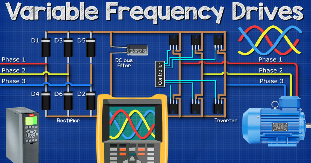
Most people think a VFD simply converts DC to AC. The actual process has four stages:
Rectification: if the input is AC (from a grid or generator), it is first converted to DC. For solar-direct VFDs, this stage is bypassed since the panel input is already DC.
DC bus capacitors: the DC power is smoothed and stored momentarily on large capacitors. This is the intermediate DC bus. It provides a stable DC voltage for the next stage.
Inversion: the inverter stage uses high-speed transistors (IGBTs) to switch the DC bus voltage on and off at precise timing intervals, creating a synthetic AC output whose frequency and voltage are both variable.
Motor output: the variable-frequency, variable-voltage AC output drives the motor. The VFD controls both voltage and frequency simultaneously to maintain the correct V/Hz ratio, which keeps the motor’s magnetic flux constant and prevents it from overheating at low speeds.
The same IGBT switching technology used in VFDs is the core of off-grid inverters. For context on how inverter selection works, see: How to Select an Off-Grid Inverter. A VFD is a specialised inverter optimised for motor loads rather than household loads.
Why a Standard Inverter Cannot Replace a VFD for Pump Applications
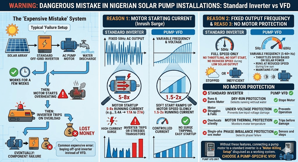
This is one of the most common and expensive mistakes in Nigerian solar pump installations. A buyer purchases a standard off-grid inverter, connects it to the solar array, and then connects the AC pump to the inverter output. The pump runs. For a few weeks, everything appears to work.
Then the motor starts overheating. Then the inverter trips on overload. Eventually one or both components fail.
Here is why this happens:
Reason 1: Motor Starting Current
An AC induction motor draws 5 to 8 times its rated running current for the first half-second to two seconds of startup. This is called the Locked Rotor Current (LRC) or inrush current. A 1 HP (750W) pump motor drawing 3.4A running current will draw 17 to 27A at startup.
A standard off-grid inverter cannot handle this surge without either tripping on overcurrent protection or suffering stress on its output transistors. A pump VFD handles this by ramping the motor speed up slowly, which limits inrush current to 1.5 to 2 times running current instead of 5 to 8 times.
Reason 2: Fixed Output Frequency
A standard off-grid inverter outputs a fixed 50 Hz AC waveform. This is correct for appliances. For a pump motor, a fixed 50 Hz output means the motor must either run at full rated speed or not run at all. There is no throttling, no soft start, and no ability to run at reduced speed when solar output is low.
A VFD outputs variable frequency from 5 Hz to 60 Hz or higher. At 5 Hz, the motor turns slowly. At 50 Hz, it runs at rated speed. At 60 Hz, it runs slightly above rated speed if needed to compensate for low irradiance conditions.
Reason 3: No Motor Protection
Standard off-grid inverters have protection designed for household loads: overcurrent, short circuit, and overvoltage. They do not have the motor-specific protections that keep pump motors alive:
Dry-run protection: detects when the pump is running without water and stops the motor
Under-voltage protection: prevents motor from running at dangerously low input voltage during low sun
Motor thermal protection: monitors motor temperature modelling and trips before winding damage occurs
Phase imbalance protection: for three-phase motors, detects if one phase fails
Overspeed protection: prevents motor from running above safe RPM
Without these protections, connecting a pump motor to a standard inverter is a motor-killing setup dressed up as a working system.
A standard off-grid inverter is designed for resistive and electronic loads: lights, TVs, fans, and refrigerators. A pump motor is a reactive inductive load with high inrush current, back-EMF, and thermal management requirements that standard inverters cannot handle correctly.
Solar VFD vs Standard VFD: What Is Different?
Standard VFDs are designed for grid-powered industrial applications. They expect a stable AC input voltage and frequency. A solar array produces variable DC voltage that changes every time a cloud passes.
A solar VFD is engineered specifically for this variable DC input. The key differences are:
Feature
Standard Industrial VFD
Solar Pump VFD
Input type
AC mains (stable 380V or 230V)
DC from solar array (variable, typically 100V to 900V depending on model)
MPPT tracking
None. Not needed for stable grid input.
Built-in MPPT. Continuously tracks maximum power point as irradiance changes.
Low-input handling
Faults and shuts down on low input voltage.
Continues running at reduced speed as solar input decreases.
Dry-run protection
Not standard. Requires external relay.
Built-in. Detects loss of pump load current and stops motor.
Starting behaviour
Requires adequate input power for full start.
Waits for sufficient panel output before attempting start. Retries automatically.
Pump curve control
Not applicable.
Some models allow programming of pump curve limits.
Price (1HP equivalent)
N25,000 to N60,000 for generic units
N45,000 to N150,000 for solar-specific units
Best use
Grid or generator-powered pumps
Solar-direct pump systems without batteries
Some installers use a standard industrial VFD with a battery inverter feeding its AC input. This works but adds cost and complexity. It is a reasonable approach for systems that already have a battery bank. For solar-direct pumping without batteries, a dedicated solar VFD is the correct component.
MPPT Inside a Solar VFD: How It Works
Maximum Power Point Tracking, or MPPT, is the algorithm that extracts the most power from a solar array at any given irradiance level.
A solar panel’s power output is not linear. At any irradiance level, there is one specific voltage at which the panel produces maximum power. This is the Maximum Power Point (MPP). If the load pulls the panel voltage below or above this point, power output drops.
The MPPT algorithm in a solar VFD continuously adjusts the input impedance (effectively the voltage it presents to the array) to keep the panel operating at its MPP. As clouds pass, irradiance drops, and the MPP shifts to a lower voltage. The MPPT algorithm tracks this shift within milliseconds and adjusts accordingly.
A solar VFD with MPPT will extract 15 to 25 per cent more energy from the same solar array compared to a non-MPPT system. On a cloudy harmattan morning in northern Nigeria, this difference determines whether the pump starts at all.
The same MPPT principle governs battery charge controllers for off-grid systems. For a detailed explanation, see: MPPT Charge Controller Selection Guide. The tracking algorithm is identical; only the load type differs.
Key VFD Parameters for Solar Pump Systems in Nigeria
A VFD has dozens of programmable parameters. For solar pump applications in Nigeria, these are the ones that determine whether your system works reliably or fails within months.
Parameter 1: Minimum Start Voltage (or Minimum DC Input Voltage)
This sets the DC input voltage threshold below which the VFD will not attempt to start the motor. Setting it too low causes the VFD to attempt starts on insufficient power, stalling the motor and drawing excessive current. Setting it too high wastes morning pumping time.
Correct setting: approximately 70 to 75 per cent of the array’s open-circuit voltage (Voc). For a 48V nominal array with Voc of 60V, set minimum start voltage at 42 to 45V.
Parameter 2: Acceleration Time (Ramp-Up Time)
This controls how quickly the VFD ramps the motor from zero to full speed. Too fast an acceleration causes high inrush current that may trip the VFD or stress the motor. Too slow wastes pumping time.
Correct setting for solar pump applications: 5 to 15 seconds acceleration time. This is longer than industrial settings (typically 2 to 5 seconds) because the solar array needs time to supply the increasing current as motor speed builds.
Motor Size
Recommended Acceleration Time
Notes
0.37 to 0.75 kW (0.5 to 1 HP)
5 to 8 seconds
Smaller motors need less ramp time
0.75 to 1.5 kW (1 to 2 HP)
8 to 12 seconds
Standard for most residential boreholes
1.5 to 3.0 kW (2 to 4 HP)
10 to 15 seconds
Larger current draw needs more ramp time
Above 3.0 kW (above 4 HP)
12 to 20 seconds
Commercial farm pumps. Verify with motor spec.
Parameter 3: Deceleration Time (Ramp-Down Time)
This controls how quickly the motor stops when power is removed. For submersible pumps in boreholes, fast deceleration creates water hammer: a pressure shock wave in the pipe that can damage fittings and the pump.
Correct setting: 10 to 30 seconds deceleration time for submersible pumps. Surface pumps with short pipe runs can use 5 to 10 seconds.
Parameter 4: Minimum Output Frequency
This sets the lowest frequency the VFD will output. Running a pump motor at very low frequency (below 15 to 20 Hz) reduces cooling water flow past the motor to a level that cannot remove heat effectively, even though the motor is still drawing current. This causes motor overheating at low speed.
Correct setting: minimum output frequency of 20 to 25 Hz for most submersible pump motors. Check the motor manufacturer’s datasheet for their minimum recommended frequency.
Parameter 5: Maximum Output Frequency
Most pump motors are rated for 50 Hz operation. Running above 50 Hz increases motor speed beyond rated RPM, which increases flow and head but also increases mechanical stress on bearings and impellers.
In solar applications, some installers set maximum frequency to 55 or 60 Hz to compensate for low-irradiance morning periods. This is acceptable for short periods but should not be the default operating point. Sustained operation above 10 per cent over rated frequency reduces motor lifespan.
Correct setting: 50 Hz for standard operation. Maximum 55 Hz as a harmattan compensation limit for short morning periods only.
Parameter 6: Dry-Run Protection Threshold
The VFD monitors motor current. When the pump runs dry (no water), the motor has no hydraulic load. Current drops below the normal running value. The VFD detects this current drop and stops the motor.
The dry-run threshold is set as a percentage of rated motor current. If the motor running current drops below this threshold for a set time period (typically 5 to 30 seconds), the VFD trips and waits a set time before retrying.
Correct setting: 40 to 60 per cent of rated motor current as the dry-run threshold. Retry delay: 10 to 30 minutes. This prevents the motor from continuously retrying when the borehole water table is low.
Dry-run protection is the single most important VFD parameter for Nigerian borehole installations. Water table drops are common in dry season. A VFD without correctly set dry-run protection will burn out a motor in minutes when the borehole runs low.
Parameter 7: V/Hz Ratio (Voltage to Frequency Ratio)
The V/Hz ratio must be maintained constant as frequency varies to keep motor magnetic flux at the correct level. Most solar VFDs set this automatically based on your motor’s rated voltage and frequency input during setup. Do not change the default V/Hz curve unless you have engineering training in motor control.
Incorrect V/Hz settings cause motor overheating at low speeds or insufficient torque at full speed. The default linear V/Hz curve is correct for standard AC induction pump motors.
How to Size a VFD for Your Solar Pump
VFD sizing follows three rules. All three must be satisfied simultaneously.
Rule 1: Match or Exceed Motor Rated Power
The VFD output power rating must be equal to or greater than the motor’s rated power. Never undersize a VFD below the motor rating.
VFD Output Rating (kW) must be greater than or equal to Motor Rated Power (kW)
Rule 2: Match or Exceed Motor Rated Current
Power ratings can be misleading due to power factor differences. Always verify that the VFD’s rated output current exceeds the motor’s full-load current (FLC) from the motor nameplate.
VFD Rated Output Current (A) must be greater than or equal to Motor Full-Load Current (A)
Rule 3: DC Input Voltage Range Must Match Solar Array
The VFD’s DC input voltage range must be compatible with your solar array’s operating voltage. The array’s Maximum Power Point voltage (Vmpp) at your highest expected temperature must fall within the VFD’s MPPT range.
In Nigerian conditions, panel temperature can reach 60 to 70 degrees Celsius on hot afternoons. At elevated temperature, panel voltage drops. The VFD must be able to track MPPT at this lower voltage.
System Voltage
Typical Solar Array Vmpp Range
Compatible VFD Input Range
12V nominal
14V to 18V
10V to 25V (small DC pump controllers)
24V nominal
28V to 36V
22V to 45V
48V nominal
52V to 72V
45V to 90V
96V to 120V
100V to 150V
90V to 200V
200V to 400V
200V to 450V
150V to 500V (most mid-range solar VFDs)
High voltage (400V to 800V)
400V to 850V
350V to 900V (large commercial VFDs)
VFD Sizing Table for Common Nigerian Pump Applications
Pump HP
Motor kW
Motor FLC (approx)
Min VFD Rating
DC Input Voltage (typical)
0.5 HP
0.37 kW
2.0A at 230V
0.37 kW / 2.5A minimum
48V to 200V depending on model
0.75 HP
0.55 kW
2.8A at 230V
0.55 kW / 3.5A minimum
72V to 300V
1 HP
0.75 kW
3.4A at 230V
0.75 kW / 4.5A minimum
100V to 400V
1.5 HP
1.1 kW
5.0A at 230V
1.1 kW / 6.0A minimum
150V to 500V
2 HP
1.5 kW
6.8A at 230V
1.5 kW / 8.0A minimum
200V to 600V
3 HP
2.2 kW
10.0A at 230V
2.2 kW / 12.0A minimum
200V to 700V
5 HP
3.7 kW
16.5A at 230V
3.7 kW / 20.0A minimum
300V to 800V
Always select the next standard VFD size above your calculated minimum. VFDs run cooler and last longer when operating below their rated capacity. A 1.1 kW VFD running a 0.75 kW motor will outlast a 0.75 kW VFD on the same motor in the hot Nigerian climate.
VFD Installation Best Practices for Nigerian Conditions
Nigeria’s climate creates specific challenges for VFD installation that are not covered in most generic installation guides.
Temperature and Ventilation
VFDs generate heat during operation. The internal IGBT transistors must stay below their rated junction temperature or they fail prematurely. In Nigeria’s ambient temperatures of 30 to 45 degrees Celsius, plus additional heat from direct sunlight on enclosures, this is a real challenge.
Always mount the VFD in a shaded, ventilated enclosure. Direct sunlight on a metal VFD enclosure can raise internal temperature by 20 to 30 degrees above ambient.
Maintain the minimum clearance distances above and below the VFD specified in the manual. Most VFDs need 100 to 150 mm clear space above and below for cooling airflow.
In very hot locations (temperatures above 40 degrees C regularly), derate the VFD: select a unit one size larger than the motor requires to compensate for thermal derating.
Never install a VFD inside a sealed metal box without ventilation in Nigerian conditions. Internal temperature will exceed 70 degrees C within an hour of operation and destroy the unit.
Dust and Harmattan Protection
Harmattan dust is fine, abrasive, and electrically conductive when combined with humidity. Dust accumulation on VFD circuit boards causes insulation breakdown and short circuits.
Use IP54 or higher rated VFD enclosures during harmattan season. IP54 provides dust protection sufficient for harmattan conditions.
If using a standard IP20 VFD in an enclosure, fit a filtered fan to provide positive pressure inside the enclosure, keeping dust out.
Clean VFD cooling fins and internal boards with compressed air every three to six months.
Cable Routing and EMI
VFDs generate high-frequency electrical noise (EMI) due to their high-speed IGBT switching. This noise can interfere with sensors, float switches, and control signals if cables are routed incorrectly.
Route motor cables (from VFD output to motor) separately from signal cables (float switch wires, sensor wires, control panel wires). Minimum 300 mm separation.
Use shielded cable for the VFD-to-motor connection if cable run exceeds 10 metres.
Connect the VFD earth terminal to a proper earth stake. An unearthed VFD is an electrocution hazard and will also produce more EMI interference.
For the correct cable sizing methodology for VFD output cables to the pump motor, apply the principles in: DC Cable Sizing for Off-Grid Solar Systems. Voltage drop limits and copper cross-section selection follow the same framework.
Surge and Lightning Protection
Nigeria has one of the highest lightning densities in the world, particularly in the Middle Belt and South-West during rainy season. A direct or nearby lightning strike creates a voltage spike that will destroy an unprotected VFD instantly.
Install a DC surge protection device (SPD) on the solar array input to the VFD. This is mandatory for any outdoor installation in Nigeria.
Install a surge arrester on the AC output side between the VFD and the motor terminals.
Earth all metal enclosures to a dedicated earth stake, not shared with building earth.
The cost of a quality DC SPD is N5,000 to N20,000. The cost of replacing a VFD after a lightning strike is N45,000 to N150,000 or more. This is not optional protection.
VFD Brands Available in Nigeria and Their Suitability for Pump Applications
Paired specifically with Lorentz PS2 pump range. Limited to Lorentz pumps.
Grundfos CU200/CU300
Denmark
Excellent. Purpose-built for Grundfos SQFlex.
Paired with SQFlex DC pump range. Not compatible with other brands.
ABB ACS series
Finland
Good with modification. Standard VFD, not solar-specific.
Requires DC input module modification for solar-direct use. Excellent quality.
Schneider Altivar ATV series
France
Good with DC input module.
Popular for commercial farm installations in Nigeria. Good dealer support in Lagos.
Solarmax / Reillo solar VFD
China/Europe
Good. Solar-specific input.
Mid-range option. Widely imported into Nigeria. Check for genuine units.
SAJ solar pump controller
China
Good for residential scale.
Popular in Nigeria for 0.5 to 3 HP range. Reasonable quality for the price.
Veikong / Gozuk solar VFD
China
Adequate for budget installations.
Lower price point. Less robust in high-heat Nigerian conditions. Buy one size up.
Generic unbranded VFDs
China
Not recommended.
No reliable warranty, no parameter documentation, high failure rate in Nigerian climate.
For residential boreholes of 0.5 to 2 HP, the SAJ and similar Chinese solar VFDs represent acceptable value when purchased from reputable suppliers. For commercial farm pumps above 2 HP or for installations where system downtime is costly, specify Schneider, ABB, or a purpose-built solar pump controller from Grundfos or Lorentz.
Three-Phase vs Single-Phase VFD for Nigerian Pump Applications
Most residential submersible pumps in Nigeria run on single-phase 230V AC motors. Most commercial farm pumps above 3 HP use three-phase 380V or 415V AC motors.
Factor
Single-Phase Motor + VFD
Three-Phase Motor + VFD
Motor availability in Nigeria
Excellent. Widely available from 0.5 to 3 HP.
Good above 3 HP. Limited below 3 HP locally.
VFD availability in Nigeria
Good. Many single-phase output VFDs available.
Good for industrial sizes. Fewer solar-specific options.
Efficiency
Slightly lower than three-phase at equivalent power.
Higher efficiency at equivalent power. Better for large farm pumps.
Starting torque
Adequate for most submersible applications.
Higher starting torque. Better for high-head applications.
Recommended application
Residential boreholes, small farm pumps up to 2 HP.
Commercial farms, boreholes above 2 to 3 HP.
VFD price premium for three-phase
Baseline
15 to 30% higher than single-phase equivalent.
For any pump above 3 HP (2.2 kW), specify a three-phase motor and three-phase VFD. The efficiency gain and motor longevity improvement justify the slight price premium over the system’s lifespan.
Common VFD Faults and What They Mean in Solar Pump Systems
Fault Code / Symptom
Most Likely Cause in Solar System
Corrective Action
OC (Overcurrent) on startup
Acceleration time too short. Array undersized for motor.
Increase acceleration time to 10 to 15 seconds. Check array output vs motor requirement.
UV (Undervoltage) fault
Solar input voltage below minimum. Cloudy morning.
Normal if occasional. If persistent, check array wiring connections and panel output.
OT (Overtemperature)
VFD enclosure too hot. Insufficient ventilation.
Improve ventilation. Add shade to enclosure. Consider larger VFD with lower thermal loading.
Dry-run trip (no fault code, motor stops)
Borehole water level dropped below pump. VFD dry-run protection activated.
Wait for retry interval. Check borehole water level. Increase pump setting depth if persistent.
Swap any two of the three motor cable connections at VFD output. Test again.
VFD starts but motor hums and does not turn
Minimum frequency too low. Motor cannot develop enough torque at startup frequency.
Increase minimum frequency to 25 Hz. Increase acceleration time. Check motor bearings.
Erratic pump speed throughout day
MPPT not tracking correctly. Possible panel shading.
Check for partial shading on array. Verify MPPT voltage range matches array Vmpp.
GF (Ground Fault) alarm
Motor winding insulation failure. Water ingress into motor terminal box.
Test motor insulation resistance (megger test). If below 1 MOhm, motor needs rewinding or replacement.
For the commissioning checklist to run before putting any solar pump system into operation, see: Off-Grid Solar System Commissioning and Troubleshooting Guide. The pre-commissioning insulation test and wiring verification steps apply directly to VFD-driven pump systems.
Complete VFD Setup Procedure for a Solar Submersible Pump in Nigeria
Follow these steps in order when commissioning a new VFD-driven solar pump system.
Verify motor nameplate data: rated voltage, rated current, rated power, rated frequency, and rated speed (RPM).
Enter motor data into VFD parameters: rated voltage, rated current, rated power, rated frequency. The VFD uses these to calculate internal motor model.
Set DC input voltage range: confirm the VFD MPPT range covers your array’s expected Vmpp from morning to midday.
Set acceleration time: 8 to 12 seconds for most residential pump motors.
Set deceleration time: 15 to 20 seconds for submersible pumps to prevent water hammer.
Set minimum output frequency: 20 to 25 Hz. Do not allow operation below this.
Set maximum output frequency: 50 Hz for standard operation. Maximum 55 Hz if harmattan compensation is needed.
Set dry-run protection threshold: 40 to 60 per cent of rated motor current.
Set dry-run retry delay: 15 to 30 minutes.
Set minimum start voltage: 70 to 75 per cent of array open-circuit voltage.
Connect float switch input to VFD control terminal (if float switch is being used for tank full stop).
Verify motor rotation direction before lowering pump into borehole. Run motor for 5 seconds at surface and check rotation matches pump impeller direction arrow.
Lower pump to correct depth. Connect drop cable to VFD output terminals. Verify cable connections are tight.
Start system in morning with partial sun to verify soft start behaviour. Motor should ramp up slowly without overcurrent trip.
Monitor and record running current at full sun. Compare to motor rated current. Running current should be 85 to 100 per cent of rated current at full pump load.
Summary
A VFD is not optional equipment in a solar AC pump system. It is the component that makes the system work reliably, protects the motor, and maximises the pumping output from your solar array through every season.
Selecting the correct VFD requires matching three parameters: output power, output current, and DC input voltage range. Setting the VFD correctly requires configuring seven key parameters: start voltage, acceleration time, deceleration time, minimum frequency, maximum frequency, dry-run threshold, and retry delay.
Nigerian conditions demand additional attention to thermal management, dust protection, lightning protection, and EMI cable routing. A VFD correctly selected, installed, and configured for Nigerian conditions will protect a pump motor for 10 to 15 years. A VFD that is wrongly sized, poorly installed, or left at factory defaults will shorten a motor’s life to months.
Q1: Can I use a regular inverter instead of a VFD for my solar borehole pump?
No. A regular off-grid inverter outputs fixed 50 Hz AC power. It has no soft-start capability, no motor protection features, and no ability to throttle motor speed when solar output is low. Connecting an AC pump motor to a standard inverter without a VFD will result in high inrush current on every start, no dry-run protection, and motor overheating during partial sun conditions. The motor will fail prematurely.
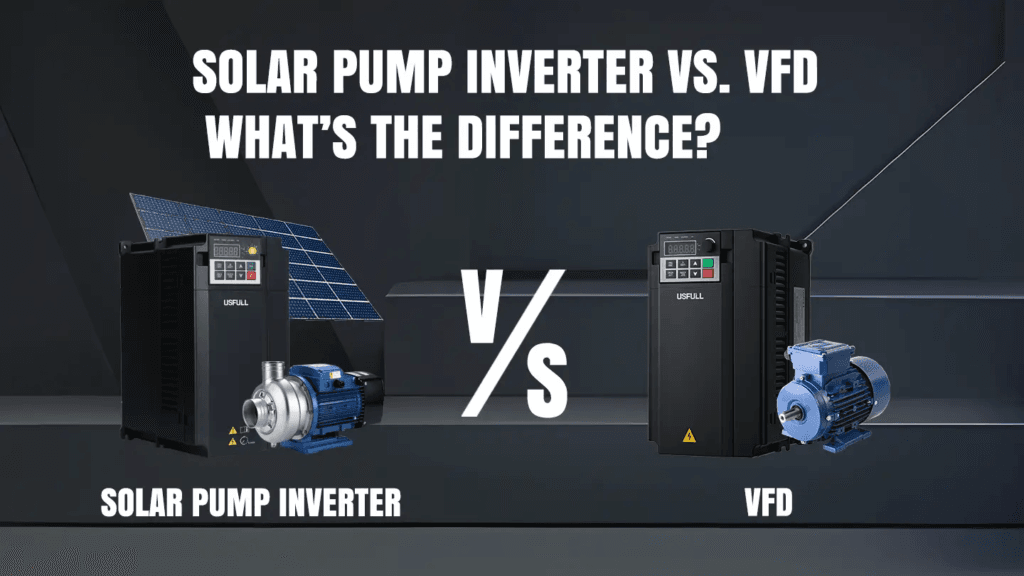
Q2: What is the difference between a solar pump controller and a VFD?
A solar pump controller is designed specifically for brushless DC pump motors. It tracks MPPT from the solar array and controls motor speed via DC signals. A VFD is designed for standard AC induction motors. It converts DC solar power into variable-frequency AC to control motor speed. Both serve the same purpose of matching motor speed to available solar power, but they are not interchangeable. A DC pump controller cannot drive an AC motor, and a VFD cannot directly drive a DC brushless motor.
Q3: My VFD trips on overcurrent every morning when the sun comes out. What is wrong?
This almost always means the acceleration time is set too short for your solar array size. When the sun rises and the array starts producing power, the VFD attempts to start the motor too quickly. The inrush current exceeds the VFD’s overcurrent threshold. Increase the acceleration time parameter from its current setting to 10 to 15 seconds and retest. If the fault persists, verify that your solar array is producing the minimum voltage and power required for the VFD to start the motor.
Q4: How do I know if my VFD dry-run protection is working correctly?
The most reliable test is to briefly close the pump’s discharge valve while the system is running. Restricting flow causes pump current to drop, simulating a dry-run condition. The VFD should trip within 5 to 30 seconds and display a dry-run or underload fault. If the VFD does not trip, the dry-run threshold is set too low or the feature is disabled. Check and correct the under-current threshold parameter before putting the system into service.
Q5: How far can the motor cable run from the VFD to the submersible pump?
The practical limit for the drop cable from VFD to submersible motor depends on cable cross-section and borehole depth. Keep voltage drop below 3 per cent of motor rated voltage. For a 230V motor, maximum acceptable voltage drop is 6.9V. Use the cable cross-section sizing table earlier in this series to select the correct cable for your depth. For most Nigerian residential boreholes of 50 to 100 metres depth, a 6 to 10 mm2 copper cable is appropriate.
Q6: My pump motor runs in the wrong direction. How do I fix this on a VFD?
Swap any two of the three motor output cables at the VFD output terminals (U, V, W). Reversing any two of the three phases reverses the rotation direction. Always check rotation direction at the surface before lowering the pump into the borehole. A pump running backwards in a borehole produces almost no water flow and can loosen the pump from its pipe connection over time.
Q7: Does a VFD work with a generator as backup power for the solar pump?
Most solar VFDs with DC input cannot accept AC generator power directly. If you need generator backup, the options are: use a separate AC-input VFD or direct-on-line starter for generator-driven operation (switching between the two manually), or install a solar-plus-battery system where the battery inverter provides stable AC to the pump regardless of power source. The simplest practical approach for most Nigerian farms is a separate generator starter for emergency use and the solar VFD for normal daily operation.
I am Engr. Ubokobong Ekpenyong, a solar specialist and lithium battery systems engineer with over five years of hands-on experience designing, assembling, and commissioning off-grid solar and energy storage systems. My work focuses on lithium battery pack architecture, BMS configuration, and system reliability in off-grid and high-demand environments.
Contains information related to marketing campaigns of the user. These are shared with Google AdWords / Google Ads when the Google Ads and Google Analytics accounts are linked together.
90 days
__utma
ID used to identify users and sessions
2 years after last activity
__utmt
Used to monitor number of Google Analytics server requests
10 minutes
__utmb
Used to distinguish new sessions and visits. This cookie is set when the GA.js javascript library is loaded and there is no existing __utmb cookie. The cookie is updated every time data is sent to the Google Analytics server.
30 minutes after last activity
__utmc
Used only with old Urchin versions of Google Analytics and not with GA.js. Was used to distinguish between new sessions and visits at the end of a session.
End of session (browser)
__utmz
Contains information about the traffic source or campaign that directed user to the website. The cookie is set when the GA.js javascript is loaded and updated when data is sent to the Google Anaytics server
6 months after last activity
__utmv
Contains custom information set by the web developer via the _setCustomVar method in Google Analytics. This cookie is updated every time new data is sent to the Google Analytics server.
2 years after last activity
__utmx
Used to determine whether a user is included in an A / B or Multivariate test.
18 months
_ga
ID used to identify users
2 years
_gali
Used by Google Analytics to determine which links on a page are being clicked
30 seconds
_ga_
ID used to identify users
2 years
_gid
ID used to identify users for 24 hours after last activity
24 hours
_gat
Used to monitor number of Google Analytics server requests when using Google Tag Manager
1 minute
You can find more information in our Cookie Policy and .


")


")
")


: Prices, Types & How to Choose")