UART vs CAN vs RS485: How Lithium Batteries Communicate With Inverters
Learn how lithium batteries communicate with inverters using CAN bus, RS485, and UART, including wiring, protocols, troubleshooting, and BMS data flow.
Most solar installers understand the power side of a battery installation: positive and negative cables, fuse ratings, busbar sizing, cable cross-sections. What they often do not understand nearly as well is the communication side: the data cables that run alongside the power cables and carry the information that determines how intelligently the system actually operates.
When a BMS communicates with an inverter, it is not just sending a heartbeat signal to say the battery is connected. It is transmitting a continuous stream of real-time data: individual cell voltages, pack SOC, charge and discharge current, temperatures, fault status, and dynamic operating limits. The inverter uses this data to make every charging and discharging decision in the system.
Getting this communication layer right is not optional. Get it wrong and the inverter operates on guesswork. Get it right and the inverter and battery function as a genuinely intelligent system that protects itself, optimises performance, and reports problems before they become failures.
This article covers the three communication interfaces found in lithium battery systems: UART, CAN bus, and RS485. We go through the electrical characteristics of each, the protocol layer that runs on top of each physical interface, what data is transmitted, how to wire each correctly, how to configure the inverter and BMS to match, and how to diagnose the most common communication failures in the field.
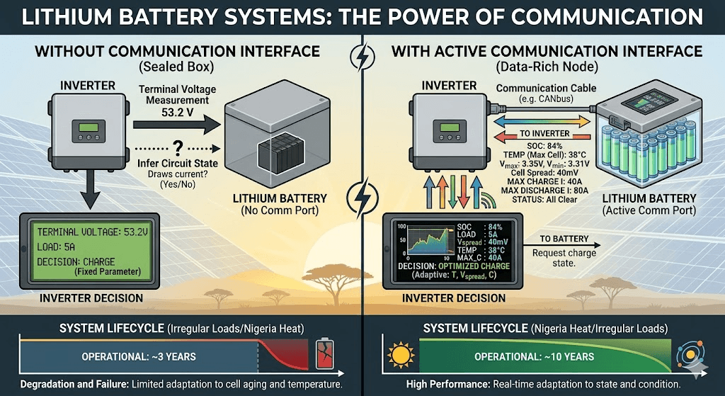
A lithium battery without a communication interface is a sealed box. The inverter knows two things about it: the terminal voltage (which it measures directly) and whether the circuit is open or closed (which it infers from whether it can draw current). That is the sum total of information available to the inverter for every operational decision it makes.
A lithium battery with an active communication interface is a data-rich node. The inverter knows the SOC to within a few percent, the temperature of the cells and MOSFETs, the voltage of every individual cell or at minimum the spread between highest and lowest, the current flowing in and out, the maximum charge and discharge current the BMS is currently willing to accept, the maximum charge voltage the BMS is currently requesting, and the status of every protection function. This is a fundamentally different quality of information, and it produces fundamentally different system behaviour.
The communication interface is what makes the difference between a solar system that operates from fixed parameters set at installation and one that adapts in real time to actual battery state. In daily cycling applications in Nigeria where ambient temperatures vary, cells age at different rates, and loads are irregular, this adaptive capability is what separates a system that performs well for a decade from one that degrades and fails inside three years.
Three serial communication interfaces appear in lithium battery systems. Each operates at a different layer of the system and serves a different function.
UART: The Internal Interface
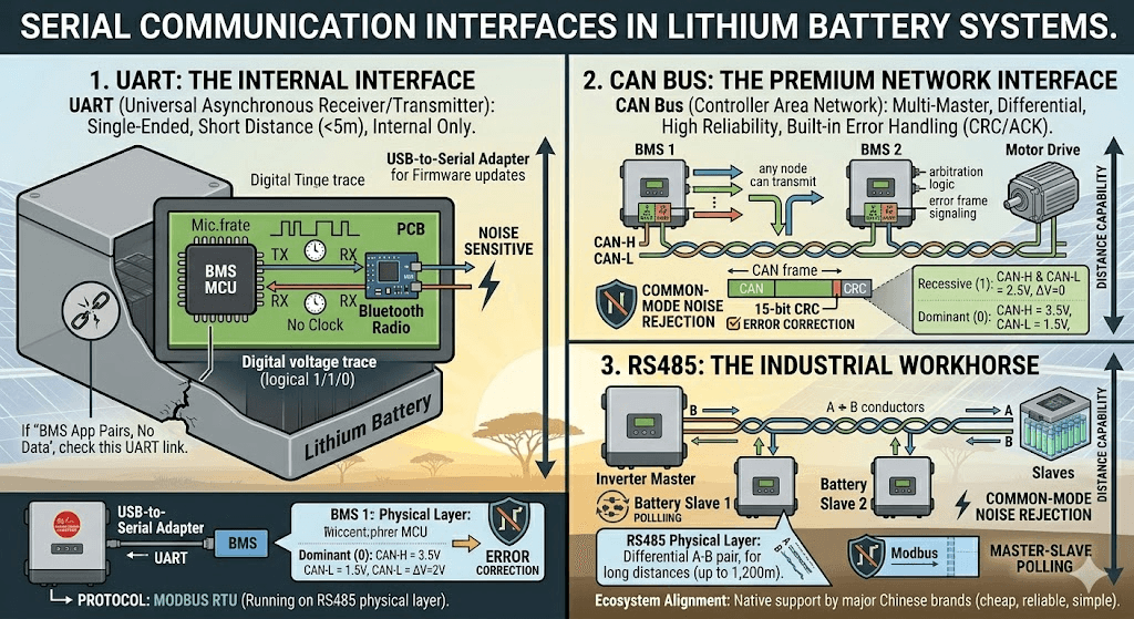
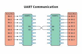
Universal Asynchronous Receiver/Transmitter is the simplest of the three. UART communicates by transmitting one bit at a time on a single wire (TX, transmit) and receiving on another (RX, receive). There is no clock wire; both ends must agree on the baud rate in advance and each end independently times the bits using that agreed rate.
UART uses single-ended voltage logic: a logical 1 is represented by one voltage level (typically 3.3V or 5V) and a logical 0 by another (0V). This single-ended approach means UART has no inherent noise immunity. Any electrical noise that changes the voltage on the TX or RX wire is indistinguishable from a legitimate signal. This limits UART to very short cable distances, typically under 5 metres, in electrically quiet environments.
In lithium battery systems, UART is an internal interface. It connects the BMS microcontroller to the Bluetooth radio module on the PCB, and it connects the BMS to a local USB-to-serial adapter for firmware updates or PC configuration. UART is not used for BMS-to-inverter communication. It does not leave the battery enclosure in normal operation.
Understanding UART matters for one specific field scenario: when the BMS Bluetooth app pairs successfully but shows no data. This symptom usually means the Bluetooth radio module is powered and communicating over the air, but the UART connection between the BMS microcontroller and the Bluetooth module is broken. In thermally stressed BMS units, solder joints on the UART interface can crack from repeated thermal cycling, breaking the data path while leaving the Bluetooth radio itself functional.
CAN Bus: The Premium Network Interface
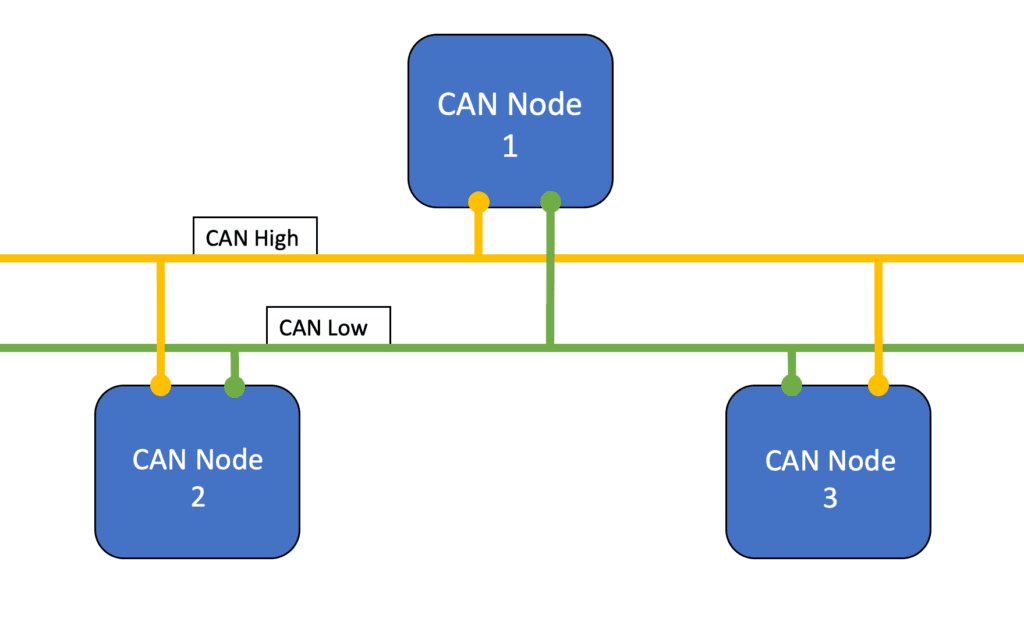
Controller Area Network was developed by Bosch in the mid-1980s for automotive applications. It is a multi-master differential serial bus: multiple devices can be connected to the same two-wire cable, any device can transmit when the bus is idle, and hardware arbitration resolves simultaneous transmission attempts without packet loss.
CAN bus uses a differential physical layer (ISO 11898). Data is transmitted as the voltage difference between two conductors, CAN-H (high) and CAN-L (low). In the recessive state (logical 1), both lines float to approximately 2.5V and their difference is zero. In the dominant state (logical 0), CAN-H rises to approximately 3.5V and CAN-L falls to approximately 1.5V, creating a 2V differential signal.
The differential nature of CAN bus is its primary advantage over UART. Any electromagnetic noise that couples onto the cable affects both CAN-H and CAN-L equally. The receiver looks only at the difference between the two conductors, so common-mode noise is rejected. This makes CAN bus robust in electrically noisy environments where power converters, motor drives, and switching power supplies generate significant electromagnetic interference.
CAN bus also has hardware-level error detection built into every frame: a 15-bit CRC, bit stuffing rules, an acknowledgement mechanism, and error frame signalling. If any node detects a transmission error, it signals an error frame, the transmitting node increments its error counter, and retransmits. If a node accumulates too many errors (indicating a persistent physical layer problem), it enters a bus-off state and stops transmitting. This self-diagnostic capability is entirely absent in RS485 Modbus.
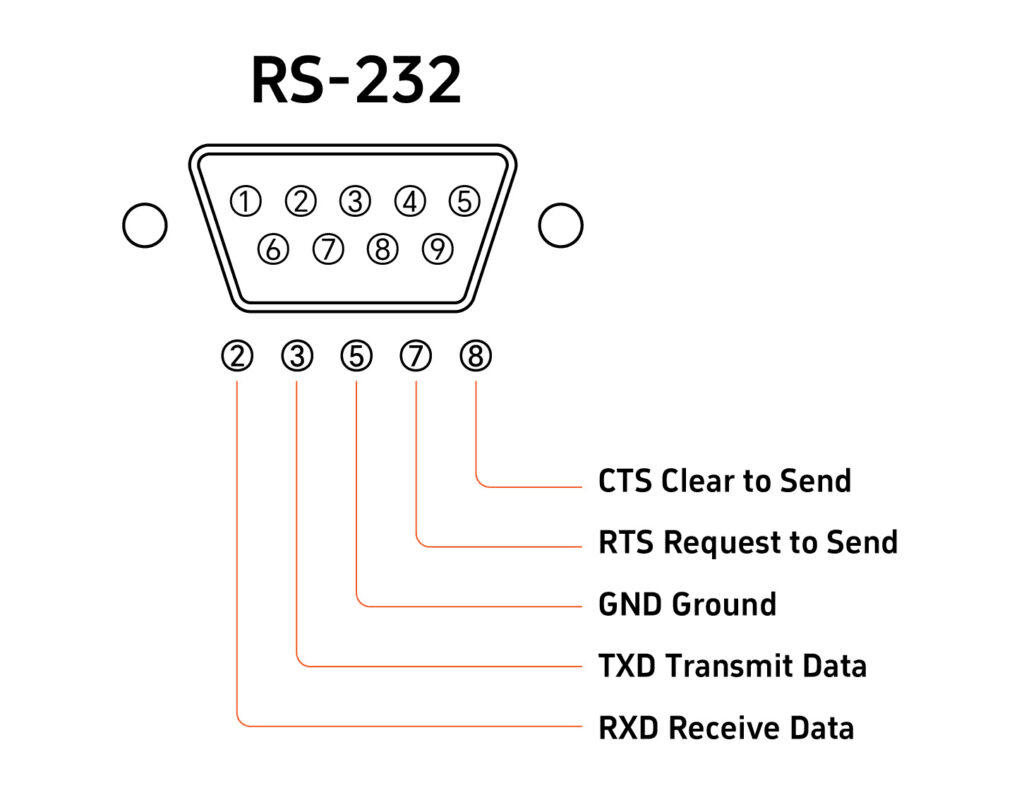
RS485:
RS485 (formally EIA-485) is a differential serial physical layer standard. Like CAN bus, it uses a differential pair (A and B conductors) and rejects common-mode noise. Unlike CAN bus, it does not define a protocol: RS485 specifies only the electrical characteristics of the physical layer. The protocol that runs on top of RS485 in battery systems is almost always Modbus RTU.
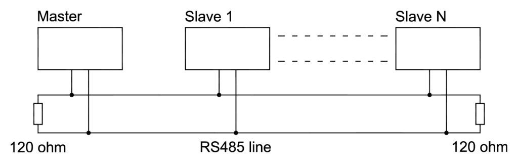
RS485 operates as a master-slave system. One device (the inverter) is the master and initiates all communication. The other devices (batteries, BMS units) are slaves that respond only when addressed. This is a simpler architecture than CAN’s multi-master bus but it means the slaves never volunteer data. The inverter must poll each slave periodically to collect updated readings.
RS485 supports cable runs up to 1,200 metres at 100 kbps, which is far longer than CAN bus at high data rates and far longer than any solar installation requires. At the 9,600 bps typical of battery communication, the distance capability is even greater. This makes RS485 reliable even in spread-out commercial installations where the inverter and battery bank are in different rooms.
The dominant reason RS485 Modbus is more common than CAN bus in the Nigerian solar market is ecosystem alignment. The major Chinese hybrid inverter brands (Deye, Growatt, Solis) and most Chinese BMS brands (JK BMS, Daly, Seplos) support RS485 Modbus natively. The BMS connects to the inverter via a two-wire RS485 cable and a terminal block, and the inverter polls it continuously. It works reliably, it is cheap to implement, and the wiring is simple.
Protocol Comparison: Complete Technical Reference
Parameter
UART
CAN Bus
RS485
Protocol type
Single-ended serial (point-to-point)
Differential serial bus (multi-node)
Differential serial (point-to-point or multi-drop)
Physical standard
TTL voltage levels (3.3V or 5V logic)
ISO 11898 (CAN-H, CAN-L differential pair)
EIA-485 (A and B differential pair)
Typical voltage swing
0V to 3.3V or 0V to 5V
Differential: +/-2V (CAN-H minus CAN-L)
Differential: +/-1.5V minimum (A minus B)
Max cable distance
1-5 metres (noise-sensitive)
40 metres at 1 Mbps; 500 metres at 125 kbps
1,200 metres at 100 kbps
Noise immunity
Poor (single-ended, no differential)
Excellent (differential + error detection)
Very good (differential pair)
Max devices on one bus
2 (point-to-point only)
Up to 110 nodes (with proper termination)
Up to 32 nodes (standard), 256 with repeaters
Bus topology
Point-to-point only
Multi-master bus; any node can transmit
Single-master / multi-slave (Modbus RTU typical)
Data rate (typical)
9,600 to 115,200 bps
125 kbps to 1 Mbps in solar BMS applications
9,600 to 115,200 bps (solar BMS typical)
Error detection
None built in (relies on application layer)
Built-in CRC, bit stuffing, ACK, error frames
Relies on Modbus CRC-16 at application layer
Message priority
None
Hardware arbitration; priority by message ID
None; master polls slaves sequentially
Protocol over physical layer
Raw bytes; no standardised framing
CAN frames with 11 or 29-bit identifiers
Modbus RTU frames (address, function, data, CRC)
Battery-side termination
N/A
120 ohm resistor required at each bus end
Not typically required for short runs under 15m
Typical BMS application
Bluetooth module interface; firmware updates; local config
Victron VE.Can; BYD; Pylontech CAN variant; premium battery systems
Deye; Growatt; Solis; Pylontech RS485; JK BMS; Daly BMS; most Chinese inverter ecosystem
Connector type (solar)
No standard (varies by BMS brand)
RJ45 (VE.Can standard); custom on some brands
Terminal block (A, B, GND) or RJ45 on some brands
WHICH TO USE
For Victron systems: CAN bus (VE.Can) via RJ45. For Deye, Growatt, Solis, and most Chinese hybrid inverters: RS485 Modbus via terminal block. For Pylontech batteries: RS485 using the Pylontech proprietary protocol. UART is never used for inverter communication. This is the 80% rule that covers the vast majority of Nigerian solar installations.
CAN Bus in Depth: Frame Structure, Arbitration, and Battery Data
The CAN Frame Structure
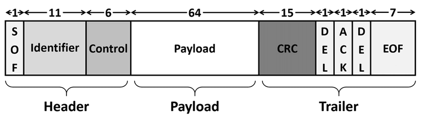
Every message on a CAN bus is transmitted as a structured frame. Understanding the frame structure explains why CAN bus can carry complex battery data reliably over a noisy electrical environment.
Frame Field
Size
Function in Battery Communication
Start of Frame (SOF)
1 bit
Single dominant bit that marks the beginning of the frame. Synchronises all nodes on the bus.
Arbitration Field
11 or 29 bits
Message identifier. Also serves as priority: lower numerical ID wins bus arbitration. In battery systems, critical messages like fault status carry lower IDs (higher priority) than routine data.
Control Field
6 bits
Data length code specifying how many bytes follow in the data field (0 to 8 bytes).
Data Field
0 to 8 bytes
The actual payload. In battery communication, this contains pack voltage, cell voltages, current, SOC, temperature, status flags, CVL, CCL, DCL, and fault codes across multiple message IDs.
CRC Field
15 bits + delimiter
Cyclic Redundancy Check calculated over the entire frame. Every receiver independently calculates the CRC and compares it to the transmitted value. Any mismatch triggers an error frame.
ACK Field
2 bits
Any node that successfully receives the frame pulls the ACK bit dominant. The transmitter monitors this: if no ACK is received, the message is retransmitted. This built-in acknowledgement is absent in RS485 Modbus.
End of Frame (EOF)
7 bits
Marks frame completion. All nodes return to idle state and bus is available for the next transmission.
Message Priority and Battery System Design
CAN bus arbitration works by comparing the message identifiers of simultaneously transmitting nodes bit by bit. A dominant bit (0) overwrites a recessive bit (1) on the bus. The node with the lower numerical identifier wins arbitration and continues transmitting; other nodes back off and retry after the winning message completes.
In a battery system, this priority mechanism is used to ensure that critical messages are never delayed by routine data. A fault status message from the BMS can be assigned a lower identifier (higher priority) than cell voltage updates. During a fault condition, the fault message always gets through first regardless of what other data is being transmitted.
In practice, most solar storage CAN bus implementations run well below the bus capacity and message priority rarely becomes a limiting factor. But the design principle matters when multiple high-data-rate devices share a CAN bus: in a Victron system with a GX device, multiple MPPT charge controllers, a BMS, and a VE.Bus inverter all on the same VE.Can bus, the arbitration mechanism prevents any single device from monopolising the bus.
CAN Bus Physical Layer Requirements
The CAN bus physical layer has three requirements that are non-negotiable for reliable operation:
Differential pair wiring: CAN-H and CAN-L must be a twisted pair. Twisting ensures that any electromagnetic interference couples onto both conductors equally, preserving the differential signal. Untwisted CAN cables work over short distances in quiet environments but fail in electrically noisy installations.
120-ohm termination at both ends: The cable is a transmission line. Without termination resistors at each physical end, signal reflections return along the cable and corrupt data frames. One 120-ohm resistor at each end absorbs the signal energy. The diagnostic check: with both devices powered off, measure resistance between CAN-H and CAN-L. A correctly double-terminated bus reads approximately 60 ohms (two 120-ohm resistors in parallel). A single-terminated bus reads 120 ohms. An unterminated bus reads open circuit.
Single-point shield grounding: If shielded CAN cable is used, connect the shield to ground at one point only. Grounding at both ends creates a ground loop that can actually introduce noise rather than removing it.
The most common CAN bus physical layer failure mode in the field and the exact steps to diagnose and resolve it are covered in detail in our article: CAN bus physical layer: the 60-second fix for communication failures. If you are commissioning a Victron system with a CAN-connected BMS, read this before starting.
RS485 and Modbus RTU in Depth: How the Battery Protocol Stack Works
The RS485 Physical Layer
RS485 uses a differential pair with A and B conductors. The receiver detects the polarity of the voltage difference: when A is more positive than B by at least 200mV, the state is a logical 1 (mark). When B is more positive than A by at least 200mV, the state is a logical 0 (space). The differential nature rejects common-mode noise with a typical common-mode rejection range of +12V to -7V, adequate for most electrical environments.
Unlike CAN bus, RS485 does not have hardware arbitration. Only one device should transmit at any time. The Modbus master (inverter) manages this by transmitting a request and waiting for the addressed slave to respond before sending the next request. If two slaves transmit simultaneously, their signals collide and both responses are corrupted.
RS485 receivers have a defined input impedance of 12k ohms minimum (one unit load). A standard RS485 bus supports up to 32 unit loads without a repeater. Most BMS units present one unit load per device. This limits the standard configuration to 32 batteries on one RS485 bus, which is far more than any typical installation requires.
Modbus RTU: The Protocol Layer
Modbus RTU is a simple master-slave protocol that uses RS485 as its physical layer. The master sends a request frame; the addressed slave sends a response frame. There is no continuous broadcast; the master must poll each slave to retrieve updated data.
Frame Field
Size
Function in Battery Communication
Device Address
1 byte
Identifies which slave device the master is addressing. In a battery system, the BMS has an address (typically 0x01 or as configured). The inverter (master) sends requests to this address.
Function Code
1 byte
Specifies the operation: 0x03 (Read Holding Registers), 0x04 (Read Input Registers), 0x06 (Write Single Register), 0x10 (Write Multiple Registers). BMS communication primarily uses read functions.
Data
Variable
Register address and quantity for read requests. Register address, count, and values for write requests. The register map (which register holds which data) is defined by the BMS manufacturer and must match the inverter’s expectation.
CRC
2 bytes
CRC-16 calculated over the entire frame. The receiver independently calculates and compares. If the CRC does not match, the slave does not respond and the master must retry. No built-in ACK like CAN; error detection only.
The Register Map: Where BMS Data Lives
The Modbus register map is the address book of the BMS. Every data point (SOC, voltage, current, temperature, fault status, CVL, CCL, DCL) lives at a specific register address. The inverter reads data by sending a read request specifying the starting register address and the number of registers to read.
Different BMS manufacturers define different register maps. JK BMS, Daly, Seplos, and Pylontech all use different register addresses for the same data. The inverter must know which register holds which data for the specific BMS it is talking to. Inverter manufacturers address this by embedding pre-configured register maps for known BMS brands in their firmware, selectable via the battery brand menu.
This is why battery brand selection in the inverter settings is not just a labelling exercise. It determines which register map the inverter uses to interpret the RS485 data it receives. Selecting the wrong battery brand means the inverter reads the wrong registers, receives nonsensical data, and either shows wildly incorrect values or reports a communication fault.
Register map conflicts also arise from BMS firmware updates. When a BMS manufacturer releases a new firmware version that changes register addresses (for example, to add new data fields), inverters that were working correctly with the old firmware may stop communicating correctly after the BMS firmware update. This is a known interoperability issue in the RS485 Modbus ecosystem and is one of the reasons why standardisation efforts like the Pylontech protocol exist.
Baud Rate and Configuration
Both the BMS and the inverter must operate at the same baud rate. The standard for solar battery communication over RS485 is 9,600 bps in the majority of implementations. Some BMS units support 19,200 or 115,200 bps. A baud rate mismatch produces garbled data that appears as a communication fault.
Baud rate is configured in the inverter battery communication settings and sometimes in the BMS app. When in doubt, start at 9,600 bps, which is the industry default for this application.
What Data the BMS Transmits:
Regardless of whether the physical layer is CAN bus or RS485, the data transmitted by a smart BMS covers the same set of parameters. The following table details every standard data type, its availability across protocols, and how the inverter uses it.
Data Type
Protocol Availability
How the Inverter Uses It
Pack voltage
Yes (both)
Total terminal voltage of the battery pack. Used by inverter as a cross-reference against its own measurement.
Pack current
Yes (both)
Charge or discharge current. Positive for charge, negative for discharge (or reversed depending on convention; must match inverter expectation).
State of Charge (SOC)
Yes (both)
BMS-calculated SOC as a percentage. The most important data point for inverter decision-making.
State of Health (SOH)
Yes (CAN primarily)
Capacity degradation percentage. Not all RS485 Modbus implementations include SOH; depends on BMS firmware and inverter support.
Cell voltage (individual)
CAN: yes via multiple messages; RS485: some implementations
Individual cell voltages. CAN bus typically transmits all cell voltages across multiple message IDs. Some RS485 Modbus register maps include cell voltages; others transmit only min/max.
Min / max cell voltage
Yes (both)
Highest and lowest cell voltage in the pack. Allows the inverter to detect cell imbalance without full per-cell data.
Temperature
Yes (both)
Cell and MOSFET temperatures. Multiple values depending on thermistor count. Min and max temperatures always transmitted.
Charge Voltage Limit (CVL)
Yes (both)
Maximum voltage the BMS will accept from the charger. Inverter adjusts charge voltage setpoint to stay below CVL.
Charge Current Limit (CCL)
Yes (both)
Maximum charge current the BMS will accept. Inverter scales back charge current to CCL when reduced.
Discharge Current Limit (DCL)
Yes (both)
Maximum discharge current the BMS permits. Inverter limits output to DCL.
Fault / alarm status
Yes (both)
Bit-field or enumerated fault flags: OVP active, UVP active, OTP active, OCP active, SCP active, balance active, communication fault, etc. Inverter uses fault flags to trigger alarms and system responses.
Cycle count
CAN: yes; RS485: varies
Total charge-discharge cycles completed. Not universally transmitted; depends on BMS and inverter support.
The inverter’s use of CVL, CCL, and DCL from this data set is the most operationally significant communication function. Our article on CVL, CCL, and DCL in real time explains in detail how the inverter adapts its behaviour in response to each of these broadcasted limits.
How to Connect Each Interface Correctly
Physical wiring errors are the most common source of communication failure at commissioning. The following table provides the specific requirements and critical field notes for each interface type.
Interface
Wiring Requirements
Critical Field Notes
CAN bus (VE.Can / RJ45)
Use a shielded twisted pair cable (Cat5e or dedicated CAN cable). Connect CAN-H to CAN-H and CAN-L to CAN-L. Do not cross the conductors. Connect shield to ground at one end only to avoid ground loops. Enable 120-ohm termination at both ends of the bus: typically a DIP switch or jumper on the BMS and on the Victron GX device or inverter.
CAN-H and CAN-L reversed is the most common wiring error. Results in no communication but does not damage hardware. Verify with a multimeter: with bus idle, CAN-H should be approximately 2.5V, CAN-L approximately 2.5V. Under traffic, CAN-H rises to ~3.5V and CAN-L drops to ~1.5V on dominant bits.
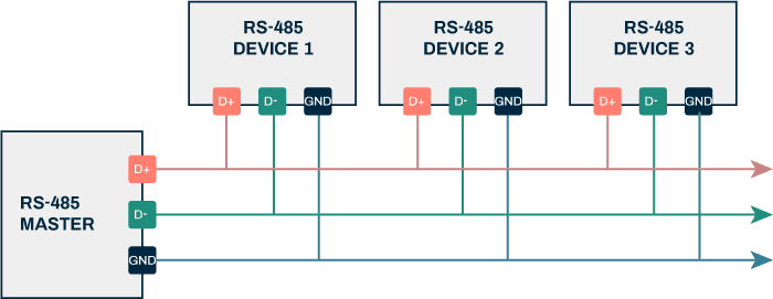
RS485 (terminal block)
Connect A to A and B to B between BMS and inverter. Include a GND connection between the two devices to establish a common reference potential. Use twisted pair wire (standard Cat5e pair is adequate for runs under 50 metres). For runs over 50 metres, use dedicated RS485 cable with 120-ohm characteristic impedance.
A and B reversed produces no communication but does not damage hardware. A missing GND connection causes intermittent communication failure, especially when one device is powered and the other is not, or when they are on different electrical circuits. This is the most frequently overlooked wiring requirement.
RS485 multi-drop (parallel batteries)
Connect all battery RS485 ports in a daisy-chain topology (not star). Each battery has a unique Modbus address configured in its BMS settings. The inverter queries each address in sequence. Maximum 32 devices without a repeater.
Star topology wiring of RS485 creates impedance mismatches and reflections that cause communication errors, especially at higher baud rates. Always daisy-chain. Terminate only at the two physical ends of the chain, not at intermediate nodes.
UART (BMS to Bluetooth module)
Internal to the BMS PCB in most smart BMS units. No field wiring required. The UART connection between the BMS MCU and the Bluetooth module is made on the PCB during manufacture.
UART is not used for inverter communication. It is the internal interface between the BMS microcontroller and the Bluetooth radio. If the BMS app shows no data despite Bluetooth pairing, the UART connection between BMS MCU and BT module may have failed (solder joint cracking in thermally stressed environments).
WIRING PRIORITY
For every BMS installation, the communication cable is as important as the power cable. Budget the same attention and care to routing, terminating, and securing the communication cable as you give to the power conductors. A communication cable that is coiled, pinched in a cabinet door, or routed directly alongside a high-current DC cable is a source of intermittent failures that can take days to diagnose.
Inverter and Battery Compatibility: Protocol Reference for Installations
The following table covers the specific inverter and battery brands most commonly deployed in Nigerian solar installations. Use it as a commissioning reference to confirm the correct protocol, connector, and configuration for each combination.
Inverter / Battery
Protocol
Connector
Configuration Notes
Victron MultiPlus / Quattro / EasySolar
VE.Can (CAN bus, 500 kbps)
RJ45 (VE.Can port)
Select battery brand in VEConfigure or Victron GX device. Enable CAN termination on Victron GX. BMS must transmit on 500 kbps CAN at VE.Can message format.
Deye SUN-xK-SG series
RS485 Modbus (Deye/Solis variant)
Terminal block (BMS port)
Set battery type in Deye inverter system settings menu. Baud rate 9600. Match protocol variant to BMS brand selected. JK BMS and Daly have specific Deye-compatible firmware variants.
Growatt SPF / SPH / MIN series
RS485 Modbus (Growatt variant)
RJ45 or terminal block depending on model
Set battery type in Growatt parameter settings (parameter 036 or equivalent). Baud rate 9600. Some Growatt models require Growatt-certified BMS firmware; standard JK firmware may not work on all Growatt models.
Solis hybrid inverters
RS485 Modbus (Solis variant)
Terminal block
Very similar to Deye configuration. Select battery brand in Solis advanced settings. Confirm register map compatibility between BMS firmware version and Solis inverter firmware version.
Goodwe hybrid inverters
CAN bus (Goodwe protocol)
RJ45
Select battery brand in Goodwe SEMS portal or local display. Goodwe natively supports most major brands. CAN termination must be enabled on both Goodwe inverter and BMS.
Pylontech US2000C / US3000C
RS485 (Pylontech proprietary protocol)
RJ45 (RS485 port on battery)
Pylontech communicates using the PYLON protocol over RS485. Select Pylontech or PYLON in inverter battery settings. The Pylontech master battery (the one connected to the inverter) aggregates data from all parallel slave batteries and presents a single communication interface.
Generic Chinese hybrid inverters (various)
RS485 Modbus (variant unknown)
Terminal block typically
Protocol variant must be identified from the inverter manual. Many Chinese OEM inverters share the same Deye or Growatt communication specification under different brand names. When in doubt, try Deye protocol first.
For the complete step-by-step configuration guide for each inverter brand, see our article: inverter-battery communication protocols in modern solar systems. It covers Victron, Deye, Growatt, Solis, and Goodwe configuration in detail with specific menu paths and parameter values.
Temperature Effects on Communication Reliability in Nigerian Conditions
Communication reliability in solar storage systems is not purely a function of wiring and configuration. Temperature plays a significant role, particularly in Nigerian field conditions where battery enclosure temperatures routinely reach 40 to 55 degC.
RS485 and Temperature
RS485 transceivers are rated for operation over a defined temperature range, typically -40 to +85 degC for industrial-grade parts and 0 to +70 degC for commercial-grade parts. Most BMS units use commercial-grade RS485 transceivers. At 55 degC enclosure temperature, these devices are operating near their rated maximum, which increases signal propagation delay and can push receiver thresholds toward their limits.
More practically, the solder joints and connector terminations on the RS485 interface degrade over time in thermally cycled environments. Thermal expansion and contraction of the PCB and connector materials create mechanical stress on solder joints that eventually manifests as intermittent connection issues. This is a leading cause of intermittent RS485 communication faults in second and third year installations in hot climates.
CAN Bus and Temperature
CAN bus transceivers are generally more robust than RS485 transceivers for high-temperature operation, partly due to the automotive heritage of the standard which demands reliability under harsh thermal conditions. However, the termination resistors are the temperature-sensitive component in CAN bus physical layers. Standard 120-ohm carbon film resistors have temperature coefficients of typically 200 to 300 ppm/degC. Over a 30 degC temperature rise, the resistance changes by less than 1%, which is negligible for CAN bus termination. This is not a practical concern in solar installations.
What This Means for Nigerian Installations
The practical implication is that any communication issue appearing 12 to 24 months after installation in a high-temperature Nigerian installation is more likely to be thermal degradation of connectors and solder joints than a configuration error. The diagnostic approach differs:
For new installations: start with configuration (protocol settings, register map, baud rate, termination).
For established installations with recently developing intermittent faults: inspect the physical connections at the BMS terminal block and at the inverter communication port. Clean, re-terminate, and re-solder where necessary.
Communication Troubleshooting: The Complete Field Diagnostic Guide
The following table covers the most common communication failure scenarios encountered in Nigerian solar installations, with specific diagnostic steps and resolution guidance for each.
Symptom
Most Likely Root Cause
Diagnostic and Resolution Steps
Inverter shows no BMS data (dashes in SOC field)
Communication not established
1. Verify cable is physically connected at both ends. 2. Verify inverter battery protocol setting matches BMS protocol. 3. Verify baud rate matches (RS485). 4. Check A/B polarity (RS485) or CAN-H/CAN-L polarity (CAN). 5. Verify CAN termination enabled at both ends (CAN only).
Intermittent communication loss (data drops out randomly)
Ground reference missing (RS485); CAN termination missing or wrong; cable too long; electrical noise
1. Add GND wire between BMS and inverter (RS485). 2. Verify 120-ohm termination at both cable ends (CAN). 3. Check cable length against protocol limit. 4. Route communication cable away from power cables to reduce EMI coupling.
Communication works but SOC reading is wrong
Protocol mismatch (inverter receiving data but misinterpreting it); BMS SOC not calibrated; wrong battery brand selected in inverter
1. Confirm inverter battery brand setting matches the exact BMS model, not just the chemistry. 2. Recalibrate BMS SOC: charge to full (OVP trip then hold for 30 min), then reset SOC to 100% in BMS app. 3. Verify BMS and inverter are using the same current direction convention.
CAN bus works initially then stops after minutes
CAN bus error state (bus-off condition); electrical noise causing excessive error frames
1. Check for electrical noise sources near the CAN cable (inverter switching noise, motor drives). 2. Verify both termination resistors are present and at 120 ohms (measure between CAN-H and CAN-L with both devices powered off: should read approximately 60 ohms for correctly double-terminated bus). 3. Check for ground loops in the shielded cable.
RS485 works with one battery but fails when second battery is added in parallel
Incorrect multi-drop wiring (star instead of daisy-chain); duplicate Modbus addresses; missing or wrong termination
1. Rewire RS485 in daisy-chain topology. 2. Assign unique Modbus addresses to each battery BMS (typically configured in BMS app). 3. Move termination resistor to the physical ends of the chain only.
Inverter shows correct SOC but does not reduce charge current near full
Inverter not configured to use dynamic limits (CVL/CCL/DCL); inverter firmware does not support dynamic limits for the selected battery protocol
1. Verify inverter firmware version supports dynamic limits for the selected battery protocol. 2. Check inverter documentation for whether CCL is honoured for the selected battery brand. Some inverters only use SOC and ignore dynamic current limits even when communication is established. In this case, configure inverter charge parameters conservatively at installation.
What Most Installers Get Wrong About Battery Communication
MISTAKE 1
Selecting the wrong battery brand in the inverter settings. This is the single most common communication configuration error. The physical cable is correct, the baud rate is correct, the A/B polarity is correct, but the inverter is reading the wrong register map because it is configured for Pylontech when a JK BMS is installed, or vice versa. Always confirm the exact BMS model against the inverter’s supported battery brand list.
MISTAKE 2
Missing the GND connection in RS485 wiring. Many installation guides show only the A and B connections. The GND wire between BMS and inverter establishes a common voltage reference for the differential signal. Without it, the common-mode voltage can drift outside the RS485 receiver’s specified range, causing intermittent communication loss that appears random but is actually triggered by specific operating conditions (e.g., when one device switches on or off and creates a voltage transient).
MISTAKE 3
Not enabling CAN termination on the Victron GX device or inverter. The Victron GX device has a software-configurable CAN termination that is disabled by default. In a two-device CAN bus (BMS and GX), both ends must be terminated. A BMS with a physical termination jumper and a GX device with software termination disabled results in a single-terminated bus that may work at short cable lengths but fails intermittently at longer runs or in noisy environments.
MISTAKE 4
Connecting RS485 in a star topology for multi-battery parallel systems. When two or more batteries are connected in parallel, each battery’s RS485 port must be daisy-chained (battery 1 to battery 2 to battery 3) not star-wired from a central point. Star wiring creates impedance discontinuities on the RS485 bus that cause signal reflections and data corruption. The fix is to rewire in a daisy-chain and terminate only at the two physical ends.
Frequently Asked Questions
What is the difference between UART, CAN bus, and RS485?
UART is a simple point-to-point serial interface using single-ended voltage logic. It connects two devices over short distances, typically under 5 metres, and has no built-in error detection or multi-device capability. It is used internally in BMS units to communicate between the BMS microcontroller and the Bluetooth module. CAN bus is a differential multi-node serial bus originally developed for automotive applications. It handles multiple devices on a single cable, has hardware-level error detection and message priority arbitration, and is highly noise-immune. RS485 is a differential serial physical layer used with Modbus RTU framing. It supports multiple devices in a daisy-chain, handles cable runs up to 1,200 metres, and is the dominant communication interface for battery-to-inverter connections in Chinese-ecosystem solar systems.
Which protocol does my BMS use to talk to my inverter?
Most BMS units in the Nigerian solar market communicate with inverters via RS485 Modbus. This includes JK BMS, Daly BMS, Seplos, and most units designed for compatibility with Deye, Growatt, and Solis inverters. Victron-based systems use CAN bus (VE.Can at 500 kbps) via RJ45 connector. Pylontech batteries use a proprietary RS485 protocol (PYLON protocol). Check your BMS specification sheet and your inverter manual to confirm the specific protocol and connector type required.
Why does CAN bus need termination resistors?
CAN bus is a differential transmission line. At high data rates, signal reflections from the unterminated ends of the cable cause voltage disturbances that corrupt data frames. The 120-ohm termination resistors at each end of the bus absorb the transmitted signal energy rather than reflecting it, preventing these disturbances. Without correct termination, CAN bus may work at short cable lengths but fails at longer runs or higher baud rates. The correct check: measure resistance between CAN-H and CAN-L with both devices powered off. A correctly double-terminated bus reads approximately 60 ohms.
What does RS485 A and B mean?
RS485 A and B are the two conductors of the differential pair. The practical rule: connect A to A and B to B between BMS and inverter as labelled. If communication does not work, swap A and B and retry. Polarity reversal does not damage hardware but prevents communication. Always include a GND connection between the two devices.
What is the Modbus register map and why does it matter?
The Modbus register map defines which data is stored at which register address in the BMS. The inverter must use the same register map when reading data from the BMS. If the inverter expects SOC at a register address where the BMS stores temperature, it reads wrong data or zero. This register map mismatch is a leading cause of communication failure when a BMS firmware update changes register addresses or when a BMS is connected to an inverter expecting a different manufacturer’s register layout.
Can I use RS485 and CAN bus at the same time on the same BMS?
Some BMS units, including certain JK BMS variants, have both RS485 and CAN bus interfaces simultaneously. This allows the BMS to communicate with an RS485 Modbus inverter while also being monitored via CAN bus by a separate data logger. The two interfaces operate independently. However, only one should serve as the primary inverter communication link. Using both simultaneously for inverter communication with different inverters creates conflicting CVL, CCL, and DCL commands.
How far can I run the RS485 cable between my BMS and inverter?
RS485 supports cable runs up to 1,200 metres at 100 kbps. At the 9,600 bps typical of solar BMS communication, the distance capability is even greater. In practice, runs over 100 metres require shielded twisted pair cable, correct grounding, and routing away from power cables. For standard solar installations where the battery and inverter are in the same room, any RS485-capable twisted pair is adequate.
What is VE.Can and how is it different from standard CAN bus?
VE.Can is Victron’s implementation of CAN bus for energy system communication. It operates at 500 kbps on a standard CAN physical layer with RJ45 connectors and uses a specific message set derived from the CANopen standard. A CAN bus device using a different message set will be visible on the physical layer but will not be understood by Victron equipment. For a BMS to work on VE.Can, it must transmit messages in the VE.Can format at 500 kbps.
Why does my inverter show communication fault even though the cable is connected?
A physical cable connection alone does not establish communication. The inverter must also be configured with the correct battery protocol setting, the correct baud rate for RS485, and correct bus termination for CAN. The most common causes are: wrong battery brand selected in inverter settings, A and B wires reversed on RS485, CAN termination not enabled at both ends, BMS address mismatch in multi-drop RS485, or BMS firmware incompatible with the inverter’s expected register map.
Does using a Bluetooth BMS app interfere with RS485 inverter communication?
No. The Bluetooth interface on a smart BMS uses UART internally to communicate with the Bluetooth radio module. This is entirely separate from the RS485 or CAN bus interface. Both can operate simultaneously without interfering with each other. Reading data from the Bluetooth app does not affect what is transmitted on the RS485 or CAN bus.
External References
CAN in Automation (CiA) — ISO 11898 CAN bus physical layer specification and VE.Can application layer documentation
Victron Energy — VE.Can protocol documentation and compatible device list
Modbus Organization — Modbus RTU specification: frame structure, function codes, and register addressing
Texas Instruments — SN65HVD series RS485 transceiver application notes: electrical characteristics and bus configuration
I am Engr. Ubokobong Ekpenyong, a solar specialist and lithium battery systems engineer with over five years of hands-on experience designing, assembling, and commissioning off-grid solar and energy storage systems. My work focuses on lithium battery pack architecture, BMS configuration, and system reliability in off-grid and high-demand environments.
Contains information related to marketing campaigns of the user. These are shared with Google AdWords / Google Ads when the Google Ads and Google Analytics accounts are linked together.
90 days
__utma
ID used to identify users and sessions
2 years after last activity
__utmt
Used to monitor number of Google Analytics server requests
10 minutes
__utmb
Used to distinguish new sessions and visits. This cookie is set when the GA.js javascript library is loaded and there is no existing __utmb cookie. The cookie is updated every time data is sent to the Google Analytics server.
30 minutes after last activity
__utmc
Used only with old Urchin versions of Google Analytics and not with GA.js. Was used to distinguish between new sessions and visits at the end of a session.
End of session (browser)
__utmz
Contains information about the traffic source or campaign that directed user to the website. The cookie is set when the GA.js javascript is loaded and updated when data is sent to the Google Anaytics server
6 months after last activity
__utmv
Contains custom information set by the web developer via the _setCustomVar method in Google Analytics. This cookie is updated every time new data is sent to the Google Analytics server.
2 years after last activity
__utmx
Used to determine whether a user is included in an A / B or Multivariate test.
18 months
_ga
ID used to identify users
2 years
_gali
Used by Google Analytics to determine which links on a page are being clicked
30 seconds
_ga_
ID used to identify users
2 years
_gid
ID used to identify users for 24 hours after last activity
24 hours
_gat
Used to monitor number of Google Analytics server requests when using Google Tag Manager
1 minute
You can find more information in our Cookie Policy and .