How to Wire Pylontech Batteries in Parallel: Master, Slave, DIP Switches, and Communication
Learn how to wire Pylontech batteries in parallel the right way. Master DC, communication, and inverter setup to avoid BMS faults and performance issues.
Most guides on connecting Pylontech batteries in parallel treat it as a simple cable job. It is not. The Pylontech parallel architecture has three distinct layers: the power layer (DC cables), the communication layer (RJ45 link chain between modules), and the inverter interface layer (CAN or RS485 from master to inverter). Getting any one of these wrong produces a bank that appears to work but is either degrading your batteries silently, running without BMS protection, or generating intermittent alarms that nobody can diagnose.
This guide covers all three layers in full technical detail. It includes the exact DIP switch function for each position on the US2000C and US3000C, how the master battery is identified and why it matters, the correct communication cable chain topology, why busbar wiring outperforms the factory daisy chain for four or more modules, the SOC matching requirement before connecting modules, and the commissioning sequence that prevents the over-current protection event that traps most first-time installers.
Quick Answer:
Identify your master battery by locating the module whose Link Port 0 is left empty. Connect all modules in a daisy chain using RJ45 link cables from Port 1 of each module to Port 0 of the next. Connect only the master battery’s CAN or RS485 port to the inverter. Match all modules to within 2% SOC before connecting. Follow the pre-charge startup sequence. For four or more modules, use a busbar instead of daisy-chained power cables.
The Three-Layer Architecture of a Pylontech Parallel Bank
Before touching any cables, understand what you are building.
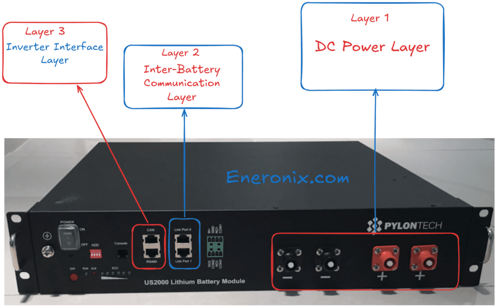
Layer 1: DC Power Layer.
This is the set of positive and negative cables that connect all battery modules into a single electrical parallel bank. All modules in parallel share the same terminal voltage. Current flows in and out of the bank through this layer.
Layer 2: Inter-Battery Communication Layer.
This is the RJ45 daisy chain that connects the BMS of each module to adjacent modules. Through this chain, every slave module reports its cell voltages, temperatures, current, and state of charge to the master module. The master aggregates this data and makes system-level decisions. Without this layer, each module operates in isolation and the bank cannot function as a coordinated unit.
Layer 3: Inverter Interface Layer.
This is the single CAN bus or RS485 cable from the master battery to the inverter. Through this cable, the master battery sends the CVL (charge voltage limit), CCL (charge current limit), and DCL (discharge current limit) for the entire bank in real time. The inverter responds to these signals by adjusting its charge and discharge behaviour accordingly.
All three layers must be correct. A bank with correct power wiring but broken inter-battery communication runs without BMS coordination across modules. A bank with correct power wiring and correct inter-battery communication but no inverter interface runs without dynamic limit management. Each failure mode is dangerous in a different way.
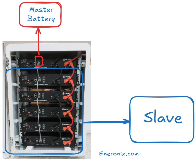
The master battery in a Pylontech parallel bank is not configured by a switch. It is identified by its physical position in the communication chain.
The master battery is the module whose Link Port 0 is left completely empty.
No cable connects to Link Port 0 of the master battery. Every other module (slave modules) has a cable entering its Link Port 0 from the previous module in the chain.
This is an important point that many installers get wrong: you do not assign master status to a battery by setting a DIP switch or pressing a button. The BMS of the module with an empty Link Port 0 automatically assumes the master role and begins broadcasting to the inverter. If you accidentally connect a cable to the Link Port 0 of what you intend to be the master, that module will detect an upstream connection and assume it is a slave, causing the entire bank’s inverter communication to fail.
For a single module (no parallel):
The single module’s Link Port 0 is empty. It is automatically the master.
For two modules:
Module A has its Link Port 0 empty (master). A cable runs from Module A’s Link Port 1 to Module B’s Link Port 0. Module B’s Link Port 1 is empty (last in chain).
For four modules:
Module A (master, Port 0 empty). Cable from A’s Port 1 to B’s Port 0. Cable from B’s Port 1 to C’s Port 0. Cable from C’s Port 1 to D’s Port 0. D’s Port 1 is empty (last in chain).
The chain extends in one direction only. There is no return cable from the last module back to the master. This is a linear daisy chain, not a ring topology.
The newest or highest-capacity module should always be the master.
The Pylontech US3000C manual states explicitly: “For same type of module, always use the latest production unit as master.” The master battery’s BMS governs the CVL, CCL, and DCL signals sent to the inverter. A newer module with updated firmware and fresh cells provides more accurate and more conservative limit management for the entire bank.
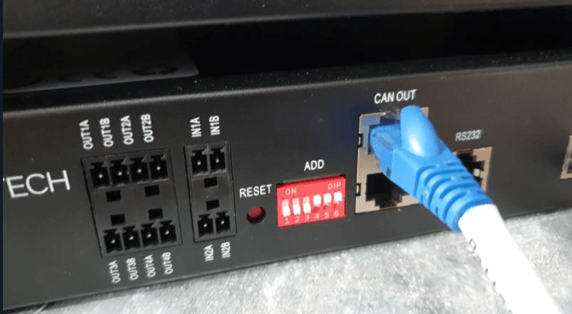
DIP Switch Functions: Full Technical Reference
The ADD switch block on the Pylontech US2000C and US3000C contains four individual DIP switches. Most installers touch only DIP1 and leave the rest at factory defaults, which is correct for most single-group configurations. But understanding all four prevents configuration errors on more complex systems.
Important physical note: The DIP switch block on US2000C and US3000C is physically mounted in reverse orientation relative to the labelling. This is explicitly acknowledged in the Pylontech US3000C manual: “Based on design of BMS, the dip switch is deployed physically reversely.” This means when the switch is physically in the DOWN position, the value is 0 (OFF). When physically UP, the value is 1 (ON). Read the switch state against the actual position, not against conventional on/off labelling.
DIP1: RS485 Baud Rate
DIP1 Position
RS485 Baud Rate
When to Use
0 (DOWN / factory default)
115,200 bps
Standard: most inverters including Growatt, Deye, Solis, Sofar
1 (UP)
9,600 bps
Only when inverter RS485 port explicitly requires 9,600 bps
The factory default is 0 (115,200 bps). Do not change DIP1 unless your specific inverter documentation specifies 9,600 bps on the RS485 port. Changing DIP1 requires a battery restart to take effect.
DIP2: CAN Termination Resistance
DIP2 Position
CAN Bus Termination
When to Use
0 (DOWN / factory default)
120 ohm termination resistor connected on BMS side
Single group mode: keep at 0
1 (UP)
120 ohm termination resistor disconnected
Multi-group mode with LV-Hub only
In single-group installations (up to 16 modules connected directly to the inverter), DIP2 must remain at 0 (factory default, termination active). The CAN bus requires a 120 ohm termination resistor at each end of the bus. In a single-group setup, the Pylontech battery acts as one end of the CAN bus and provides this termination internally. Removing it (DIP2 = 1) causes CAN signal reflections and communication errors.
In multi-group mode with an LV-Hub, DIP switch settings change and are covered in the LV-Hub section below.
Unlike DIP1, changing DIP2 does not require a battery restart.
DIP3 and DIP4: Reserved
DIP3 and DIP4 are reserved positions in the US2000C and US3000C. They serve no user-configurable function in single-group mode. Leave both at factory default (0, DOWN position). Do not change them.
Factory default for all US2000C and US3000C single-group installations: all four DIP switches at 0 (all physically DOWN).
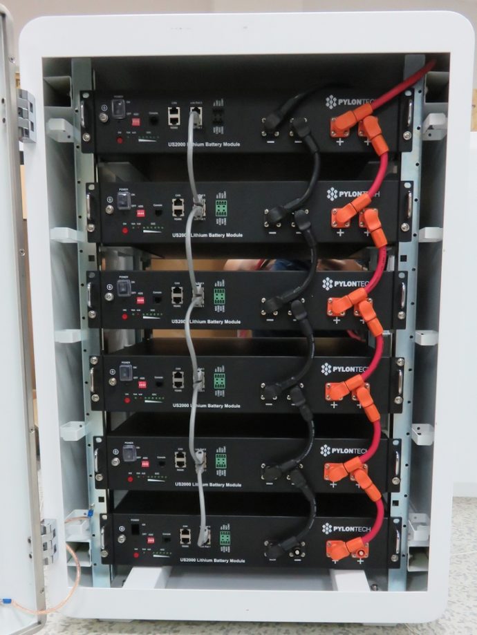
Power Cable Wiring: Daisy Chain vs Busbar
This is the technical decision that most Nigerian installers skip, and it is the one that causes the most field problems on larger banks.
The Daisy Chain Method (Factory Supplied Cables)
Pylontech supplies Amphenol connector cables rated at 25mm² cross-section for connecting modules in a power daisy chain. In this configuration, the first module connects to the second, the second connects to the third, and so on. The last module in the chain connects to the inverter via the battery cable.
The daisy chain is the default Pylontech-supported method. For two or three modules, it is adequate. For four or more modules, it introduces a current distribution problem that Pylontech’s own documentation does not explicitly flag, but which has been extensively documented in field installations.
Why daisy chaining becomes a problem at four or more modules:
In a daisy-chained bank, the modules at the two ends of the chain are furthest from each other. When the bank is connected to the inverter from one end (as most installations are), current flows preferentially from the module closest to the inverter output terminal. The module at the opposite end of the chain sees the full resistance of all the inter-module connection cables in series before its current reaches the output terminal.
At 4 modules with 25mm² cables and approximately 8-inch inter-module cable runs, the resistance difference between the nearest and furthest module is small but non-zero. Under sustained high-current loads (5kVA inverter at 60 to 80% load), this resistance imbalance causes the nearest module to discharge faster and accept more charge current than the farthest module. Over hundreds of cycles, this creates SOC divergence between modules, which triggers BMS imbalance alarms and reduces the effective capacity of the bank.
The Victron Wiring Unlimited guide specifically recommends taking the inverter cable connections from opposite ends of a daisy-chained battery stack (positive from one end, negative from the other end) to partially equalise the current distribution even when using daisy chain power cables.
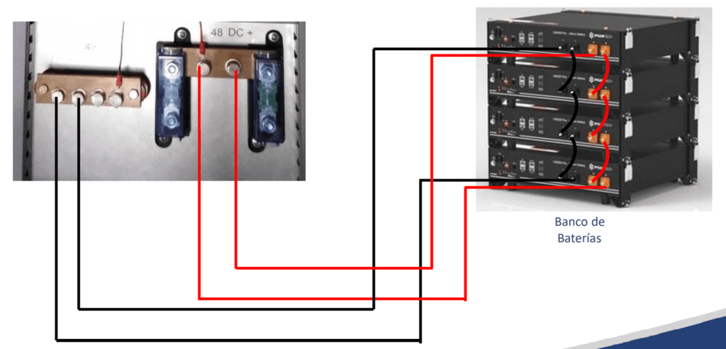
The Busbar Method (Recommended for Four or More Modules)
In the busbar method, each module is individually connected to a shared positive busbar and a shared negative busbar using equal-length cables. The inverter connects from the busbar, not from any individual module.
This topology ensures that every module has exactly the same cable resistance to the busbar and therefore draws and delivers current in equal proportion at all times. Current distribution is governed by the impedance of each module’s cells rather than by cable topology.
Busbar method specifications for Nigerian installations:
Each individual cable from module to busbar must be sized for the maximum current of one module: 50A for US2000C, 74A for US3000C, 100A for US5000. Use a minimum of 10mm² cable per US2000C or US3000C module connection. Do not use the factory 25mm² Amphenol cables between module and busbar unless you can source compatible Amphenol-to-lug adapters.
The cable from the busbar to the inverter must be sized for the total bank current. For a 4-module US3000C bank (total 296A maximum), use a minimum of 70mm² cable for any run over 1 metre. For a 6-module bank, use 95mm² or larger.
All individual cables from each module to the busbar must be the same length and the same cross-section. Cables of different lengths create different resistance paths and reintroduce the current distribution problem that the busbar method is designed to solve.
Install a fuse or DC circuit breaker between each module’s positive terminal and the busbar, rated at 1.25 times the module’s maximum continuous current. For US3000C: 74A x 1.25 = 92.5A, so a 100A DC fuse per module.
SOC Matching: The Requirement Most Installers Skip
Before connecting any Pylontech modules in parallel for the first time, or when adding a new module to an existing bank, all modules must be at the same state of charge within a tolerance of approximately 2%.
Why this matters at the cell level:
When you connect two LiFePO4 modules with different SOC levels in parallel, they are suddenly at the same terminal voltage (because they are physically connected). But their internal electrochemical state is different. The module at higher SOC has cells at higher lithium concentration on the anode. The module at lower SOC has cells at lower lithium concentration. When connected, a large equalisation current flows from the high-SOC module to the low-SOC module through the power cables and the Amphenol connectors, without the BMS having any say in the magnitude or duration of that current.
For a Pylontech US3000C module at 100% SOC (approximately 53V) connected to a US3000C module at 50% SOC (approximately 51.5V), the 1.5V potential difference across 25mm² cable of approximately 0.5 metres produces an instantaneous equalisation current of approximately 40 to 60A. This is within spec. But for a module at 100% connected to a module at 10% (approximately 48V), the potential difference is approximately 5V, and the equalisation current can exceed 100A for several seconds.
The BMS over-current protection may trigger. If it does, the protection flag is set and the bank will not operate normally until reset. The fix is to charge or discharge the modules individually before connecting them.
Practical SOC matching procedure:
Turn on each module individually. Observe the SOC LED indicators. Each lit LED represents approximately 16% of capacity (US2000C has 6 SOC LEDs, each representing approximately 16.7%). Match all modules so they show the same number of SOC LEDs before connecting.
For a new installation where all modules arrive from the same batch at approximately the same SOC, this check takes one minute. For an existing bank where you are adding a new module, you need to charge or partially discharge the new module before connecting it. Connect the new module to a standalone charger first, monitor its SOC until it matches the existing bank, then connect it to the bank with the bank in a resting state (no charge or discharge occurring).
Communication Cable Wiring: The Complete Topology
The inter-battery communication chain and the inverter communication cable are separate physical connections using different ports on the battery front panel. Confusing them is one of the most common installation errors.
Inter-Battery Link Ports (RJ45, Standard Straight-Through Cable)
The Link Port 0 and Link Port 1 on each module are used exclusively for connecting modules to each other in the communication daisy chain. Use standard straight-through RJ45 ethernet cables (Cat5e or Cat6) for these connections. Do not use crossover cables.
Chain construction:
Module A (master): Link Port 0 empty. Link Port 1 connects to Module B’s Link Port 0.
Module B: Link Port 0 receives from Module A’s Port 1. Module B’s Link Port 1 connects to Module C’s Link Port 0.
Last module in chain: Link Port 0 receives from previous module. Link Port 1 is empty.
The communication daisy chain is physically and electrically separate from the power cable daisy chain. You can run the power cables from a busbar topology and still run the communication chain as a daisy chain. These are independent layers.
Maximum cable length between modules in the communication chain is not published by Pylontech, but installations using standard 2-metre Cat5e cables between all modules in a 16-module stack have been confirmed functional.
CAN Port (Master Battery to Inverter)
The CAN port on the master battery connects to the inverter’s CAN interface. The CAN bus runs at 500 kbps with 120 ohm characteristic impedance. The cable from master to inverter must be correctly terminated at both ends. In a single-group system, DIP2 set to 0 (default) provides the 120 ohm termination at the battery end. The inverter provides termination at its end.
The correct cable for US2000C and US3000C to Victron inverters is Victron part number ASS030710018 (VE.Can to CAN-bus BMS Type A). This is not interchangeable with the Type B cable used for older US2000 and US3000 models. Using the wrong cable produces no communication.
For Growatt, Deye, and Solis inverters, use the battery communication cable specified by the inverter manufacturer for Pylontech LV (low voltage) batteries. These are brand-specific. Verify the pinout against both the inverter manual and the Pylontech port definition before purchasing.
RS485 Port (Alternative to CAN)
The RS485 port provides an alternative communication path from the master battery to the inverter. RS485 and CAN carry the same data (CVL, CCL, DCL, SOC, alarm flags). The choice between CAN and RS485 is determined by what your inverter supports.
RS485 is a two-wire differential pair (A and B lines) with a 120 ohm termination at each end of the bus. The RS485 cable connects only from the master battery to the inverter. It does not daisy chain between slave modules.
For inverters that support both CAN and RS485, CAN is preferred because it is less susceptible to noise at higher baud rates and provides a more robust keep-alive signal.
Which Port Connects to the Inverter?
Connect only the master battery’s CAN port (or RS485 port) to the inverter. No slave battery connects to the inverter directly. The master aggregates all battery data from the inter-battery chain and acts as the single interface to the inverter for the entire bank.
Connecting a slave battery’s CAN port to the inverter in addition to the master’s will create a bus conflict. Two devices asserting on the same CAN bus with different node IDs produces CAN error frames and unpredictable communication behaviour.
Multi-Group Configuration with the LV-Hub
When a single parallel group exceeds 16 modules, the Pylontech LV-Hub is required. The LV-Hub acts as a CAN bus aggregator, collecting data from up to 6 independent groups of up to 16 modules each, and presenting a single unified interface to the inverter.
When the LV-Hub Is and Is Not Required
Configuration
LV-Hub Required?
1 to 16 US2000C or US3000C in one group
No
17 to 96 US2000C or US3000C across multiple groups
Yes
Any configuration where a single inverter manages more than 16 modules
Yes
Most Nigerian residential and small commercial systems do not require the LV-Hub. A 16-module US3000C bank provides 56.8 kWh of usable capacity at 95% DoD, which exceeds the requirement of virtually all residential Nigerian solar installations.
DIP Switch Configuration for Multi-Group Mode
When using the LV-Hub, the DIP switch settings on master batteries (one per group) change from the single-group defaults.
For the master battery of each group: set DIP2 to 1 (UP, CAN termination disconnected). The LV-Hub provides CAN bus termination for the multi-group bus.
For all slave batteries in every group: all DIP switches remain at factory default (0000, all DOWN).
Multi-group startup sequence:
Power on all battery modules in all groups (rocker switches on, then START button on each group’s master battery separately).
Once all batteries in all groups are running (RUN lights active), change the DIP2 of the master battery in Group 1 to position 1 (UP).
Connect the CAN communication cable from the Group 1 master to LV-Hub Port 1.
Repeat for each additional group, connecting each group’s master to successive LV-Hub ports.
Connect the LV-Hub to the inverter using the appropriate LV-Hub to inverter communication cable.
Power on the LV-Hub.
The LV-Hub LEDs confirm how many groups are detected. Each group’s detection is indicated by a port LED on the hub.
The Correct Startup Sequence
The startup sequence is not a formality. It exists because the Pylontech BMS has a pre-charge function that limits inrush current to the inverter capacitor bank. Skipping it causes an immediate over-current protection event that appears to be a battery fault but is an installation procedure error.
Correct sequence, single group, any number of modules:
Ensure all power cables (DC positive and negative from battery to inverter) are physically connected and the circuit breaker between battery and inverter is closed.
Ensure the communication cable (CAN or RS485) from master battery to inverter is connected.
Turn on the rocker switch on all battery modules to the ON position. At this point, the modules are in standby — the BMS is active but the power output MOS switches are not fully conducting.
On the master battery, press and hold the red START button for more than 0.5 seconds. Release. The master battery’s pre-charge circuit activates, delivering a controlled current ramp to charge the inverter capacitor bank. The master battery’s LEDs will illuminate. Slave batteries will power on sequentially one by one.
Wait until all modules show stable RUN LED operation (all flashing or solid depending on state).
Power on the inverter.
Do not power on the inverter before completing Step 5. An inverter powered on with discharged capacitors draws inrush current directly from the battery without the pre-charge circuit limiting it. The inrush can reach 200 to 400A for 20 to 50 milliseconds. The BMS sees this as a short circuit and triggers over-current protection.
If over-current protection triggers during startup:
Turn off all rocker switches. Disconnect the positive power cable from the inverter terminal. Wait 5 minutes for the inverter capacitors to discharge through internal bleeder resistors. Reconnect the positive cable. Repeat the startup sequence correctly from Step 1.
Commissioning Verification Checklist
After completing wiring and startup, verify the following before considering the installation complete.
Communication verification:
Navigate to the inverter battery status display. Confirm the following are visible as real-time values, not static numbers:
Battery state of charge percentage (should change when load is applied or removed)
BMS-reported voltage (will show cell-resolution changes, not just rough terminal voltage)
Charge current limit (CCL) — should be a non-zero value when battery is below 100% SOC
Discharge current limit (DCL) — should be a non-zero value when battery is above minimum SOC
If only terminal voltage and a smooth incrementing percentage are visible, BMS communication is not active. Do not proceed with commissioning until this is resolved.
Module count verification:
On Victron systems, navigate to Device List, select the Pylontech battery, and open the Parameters screen. The CCL value shown should be approximately equal to the recommended charge current per module multiplied by the number of modules. For a 4-module US3000C bank: 4 x 37A = 148A CCL. If the CCL shows only 37A, only one module is communicating.
On Growatt and Deye inverters, the battery module count is often visible in the battery information screen. If not, the CCL multiplication method still applies.
Temperature verification:
The BMS-reported temperature from the master battery should read between 20 and 45 degrees Celsius for a newly commissioned system. A temperature reading of 0 from the BMS is a known symptom of communication at the wrong baud rate (RS485 DIP1 set incorrectly).
SOC consistency check:
After the system has been running for 24 to 48 hours with at least one full charge and discharge cycle, the SOC LED indicators on all modules should show approximately the same number of LEDs lit.
Common Wiring Mistakes and Their Symptoms
Mistake
What You See
Root Cause
Cable connected to master’s Link Port 0
Inverter shows no battery detected or generic voltage-only data
Master has become slave; no module is broadcasting to inverter
DIP1 changed to 9,600 bps without inverter requiring it
No RS485 communication, inverter shows battery communication error
Baud rate mismatch between battery and inverter
Power cable daisy chain with 5+ modules, inverter connection at one end
End modules degrade faster, SOC divergence over months
Resistance imbalance in daisy chain path
New module connected to existing bank without SOC matching
Over-current protection trips immediately on connection
Equalisation current exceeds BMS threshold
Startup: inverter powered on before bank stabilises
Over-current protection, bank appears dead
Inverter capacitor inrush current without pre-charge circuit
Communication chain break (damaged RJ45 connector)
Module count drops, CCL value lower than expected
Break in inter-battery daisy chain
Frequently Asked Questions
How do I identify the master battery in a Pylontech parallel bank?
The master battery is the module whose Link Port 0 has no cable connected to it. No configuration is required. The BMS of any module with an empty Link Port 0 automatically takes the master role and begins transmitting CVL, CCL, DCL, and alarm data to the inverter. All modules with a cable entering their Link Port 0 operate as slaves.
Do I need to change the DIP switches when adding more Pylontech batteries in parallel?
No, for configurations up to 16 modules in a single group. The factory default setting (all four DIP switches at 0, physically DOWN) is correct for single-group parallel configurations of any size up to 16 modules. Only DIP1 may need to change if your inverter’s RS485 port requires 9,600 bps.
Why does my Pylontech bank trip over-current protection every time I start the inverter?
You are powering the inverter on before completing the Pylontech pre-charge startup sequence. The correct sequence is: close the DC circuit breaker, turn on all battery rocker switches, press and hold the START button on the master battery for 0.5 seconds, wait for all module LEDs to show stable operation, then power on the inverter.
Can I connect the CAN cable to a slave battery instead of the master?
No. The CAN port must connect only to the master battery (the module with empty Link Port 0). A slave battery’s CAN port either has no data to transmit to the inverter or creates a bus conflict with the master.
What cable should I use for the inter-battery link chain?
Standard straight-through RJ45 Cat5e or Cat6 ethernet cable. Do not use crossover cables. Most Pylontech battery packs include short RJ45 link cables for rack installations.
Can I mix the busbar method for power cables with the daisy chain method for communication cables?
Yes, and this is the recommended approach for four or more modules. The DC power layer and the inter-battery communication layer are completely independent. You can run individual 10mm² power cables from each module to a shared busbar while still running the RJ45 inter-battery communication chain from module to module in sequence.
Do I need to match SOC when adding a new Pylontech battery to an existing bank?
Yes. Before connecting a new module to an existing bank, bring the new module’s SOC to within approximately 2% of the existing bank’s SOC. A voltage difference greater than approximately 1V between the new module and the existing bank produces an equalisation current that may exceed the BMS over-current threshold.
How do I verify all Pylontech modules are communicating correctly after installation?
Check the CCL (charge current limit) value reported by the BMS to the inverter. This value should equal the recommended charge current per module multiplied by the number of modules connected. For US3000C modules: 37A x number of modules. For US2000C modules: 25A x number of modules.
How many Pylontech batteries can I connect in parallel without an LV-Hub?
Up to 16 US2000C or US3000C modules can operate in a single group without the Pylontech LV-Hub. At 16 US3000C modules, the maximum bank capacity is 56.8 kWh at 95% depth of discharge. Systems requiring more than 16 modules need the LV-Hub, which supports up to 6 groups of 16 modules each.
Conclusion
A correctly wired Pylontech parallel bank requires precision at three layers simultaneously: the DC power layer where current paths must be equalised, the inter-battery communication layer where the daisy chain topology determines which module acts as master, and the inverter interface layer where only the master speaks to the inverter.
The DIP switches are simple: factory default (all at 0) is correct for all single-group installations. Do not change them unless you have a specific reason confirmed by your inverter documentation.
The master battery is always the module with empty Link Port 0. The newest, highest-capacity module should fill that role.
For four or more modules in a Nigerian installation, use a busbar for the power cables. The factory daisy chain method introduces current distribution asymmetry that accumulates over time as SOC divergence and accelerated degradation in the modules nearest the inverter output terminal.
Match SOC before connecting any module to an existing bank. Follow the pre-charge startup sequence on every startup. Verify BMS communication is active by checking CCL values before commissioning is complete.
I am Engr. Ubokobong Ekpenyong, a solar specialist and lithium battery systems engineer with over five years of hands-on experience designing, assembling, and commissioning off-grid solar and energy storage systems. My work focuses on lithium battery pack architecture, BMS configuration, and system reliability in off-grid and high-demand environments.
Contains information related to marketing campaigns of the user. These are shared with Google AdWords / Google Ads when the Google Ads and Google Analytics accounts are linked together.
90 days
__utma
ID used to identify users and sessions
2 years after last activity
__utmt
Used to monitor number of Google Analytics server requests
10 minutes
__utmb
Used to distinguish new sessions and visits. This cookie is set when the GA.js javascript library is loaded and there is no existing __utmb cookie. The cookie is updated every time data is sent to the Google Analytics server.
30 minutes after last activity
__utmc
Used only with old Urchin versions of Google Analytics and not with GA.js. Was used to distinguish between new sessions and visits at the end of a session.
End of session (browser)
__utmz
Contains information about the traffic source or campaign that directed user to the website. The cookie is set when the GA.js javascript is loaded and updated when data is sent to the Google Anaytics server
6 months after last activity
__utmv
Contains custom information set by the web developer via the _setCustomVar method in Google Analytics. This cookie is updated every time new data is sent to the Google Analytics server.
2 years after last activity
__utmx
Used to determine whether a user is included in an A / B or Multivariate test.
18 months
_ga
ID used to identify users
2 years
_gali
Used by Google Analytics to determine which links on a page are being clicked
30 seconds
_ga_
ID used to identify users
2 years
_gid
ID used to identify users for 24 hours after last activity
24 hours
_gat
Used to monitor number of Google Analytics server requests when using Google Tag Manager
1 minute
You can find more information in our Cookie Policy and .


: Honest Brand-by-Brand Comparison")