How to Size an Off-Grid Solar System for Commercial Buildings (With Worked Example)
Learn how to size off-grid solar systems for small commercial and light industrial loads. This detailed guide covers load audits, surge calculations, battery bank sizing, MPPT configuration, and inverter selection for reliable, scalable commercial solar installations.
How to Size an Off-Grid Solar System for Commercial Buildings
A residential off-grid solar system installer received a referral from an existing client: a small professional services office in the same neighborhood, two floors, ten staff, running a generator for eight hours a day and spending more on fuel than the client’s house next door. The installer was comfortable with the work. The load audit, the array sizing, the battery bank sizing, the inverter selection, all followed the same methodology that had produced reliable residential systems across dozens of installations. The system was commissioned correctly, the VRM portal showed normal operating data, and the office manager signed off at handover.
Three weeks later the office manager called to report that the system was shutting down every Tuesday and Thursday afternoon at roughly the same time. The Cerbo GX alarm log showed an inverter overload event at 14:23 on Tuesday and 14:31 on Thursday. The AC load reading in the seconds before each shutdown showed a spike to 11,400W, nearly double the inverter’s rated capacity.
The root cause took twenty minutes to find. The building had an overhead water tank served by a 1,500W submersible pump that started automatically whenever the float switch dropped below its threshold. The pump had not been mentioned during the load audit because the office manager considered it part of the building infrastructure rather than an office load. Its 4kW starting surge, arriving on top of the full afternoon AC and computer load, exceeded the inverter’s surge rating every time it started.
Commercial load audits require a different discipline from residential ones. This post establishes what that discipline looks like and applies it to a complete commercial system specification.
How Commercial Loads Differ from Residential
The residential load audit methodology in Post #1: How to Do a Proper Load Audit Before Sizing an Off-Grid System, identifies loads by room, estimates their running power, and multiplies by daily usage hours to produce a daily energy demand figure. This methodology works for residential installations because residential loads are well understood, their usage patterns follow predictable domestic routines, and the consequence of a sizing error is a household inconvenience rather than a business disruption. The same methodology applied to a commercial installation without modification will miss load categories that do not exist in residential buildings, underestimate the peak simultaneous load that the inverter must handle, and produce a battery bank sized for the wrong overnight scenario.
The three differences between commercial and residential loads that directly affect system sizing are the load profile shape, the peak-to-average load ratio, and the outage consequence. A residential load profile has a pronounced evening peak and a low overnight baseline. A commercial load profile is flatter during operating hours and then drops sharply at close of business. The evening peak that drives residential battery sizing does not exist on a commercial system. What drives commercial battery sizing is the overnight standby load and the worst-case overcast day operating deficit.
The peak-to-average ratio is higher in commercial installations because motor loads, water pumps, air compressor motors, refrigeration compressors, lift motors, are more common and more powerful than in residential buildings. These loads produce starting surge currents of 5 to 8 times their running current, and in a commercial building several motor loads may start within seconds of each other during the morning startup sequence. The inverter must handle this combined surge demand without tripping.
The outage consequence distinguishes commercial sizing from residential sizing in a way that affects the autonomy specification. A commercial system sized for two autonomy days reflects a revenue protection standard: the client can quantify the revenue lost per hour of outage, and the autonomy specification is the engineering translation of the client’s tolerance for that revenue loss.
The commercial load audit follows the same structure as the residential audit in Post #1 with three additions: every motor load must be identified separately and its starting surge current estimated, every standby load must be identified and its 24-hour daily energy contribution calculated independently, and the peak simultaneous load must be calculated explicitly including the worst-case motor starting scenario.
The reference office for this post is a two-floor professional services building with 200 square metres of conditioned floor area, ten staff, an operating day of 08:00 to 17:00, a server room with continuous cooling, and a building water system served by a submersible pump.
Operating-Hours Loads
Lighting: 20 x 18W LED panels = 360W, 8hr/day
E_lighting = 360W x 8h = 2,880Wh/day
Computers and monitors: 10 workstations x 80W = 800W, 8hr/day
E_computers = 800W x 8h = 6,400Wh/day
Air conditioning: 2 x 1,500W at 65% duty cycle
Average AC power = 2 x 1,500W x 0.65 = 1,950W
E_AC = 1,950W x 8h = 15,600Wh/day
Water pump: 1,500W, 0.5hr/day total run time
E_pump = 1,500W x 0.5h = 750Wh/day
Note: motor load, starting surge = 6 x 1,500W = 9,000W
The 14,194W surge demand is the parameter that governs the inverter specification. It is more than twice the continuous running load and nearly three times a standard single-phase Multiplus-II 48/5000’s surge rating of 9,000VA. This is the calculation that the residential methodology, applied without identifying the pump as a motor load, would not have produced.
Load
Running Power
Daily Hours
Daily Energy
Surge
Lighting
360W
8hr
2,880Wh
None
Computers
800W
8hr
6,400Wh
None
Air conditioning (x2)
3,334VA
8hr
15,600Wh
3x at start
Water pump
1,500W
0.5hr
750Wh
6x = 9,000W
Networking
150W
24hr
3,600Wh
None
Server room cooling
500W
24hr
12,000Wh
None
Access control/alarm
50W
24hr
1,200Wh
None
Total
5,194W running
42,430Wh/day
14,194W surge
Array Sizing for Commercial Operations
The array sizing calculation for a commercial installation uses the same governing equation as Posts #4: Solar Array Sizing for Off-Grid Lithium Battery Systems and #5: Series vs Parallel vs Series-Parallel Solar Array Wiring, but the energy demand input requires a distinction that does not exist in the residential calculation. In a commercial system operating during daylight hours, the array generates at the same time as the largest loads are running, and its output directly offsets the operating-hours demand in real time. The battery bank’s function shifts from overnight storage to overcast-day buffer.
The array must be sized to cover the full daily energy demand, including the standby loads that run overnight, because on a clear day the array must harvest enough energy to serve the operating-hours loads directly, recharge the energy consumed by the overnight standby loads the previous night, and maintain the battery bank at a high state of charge for the next overcast day:
Battery bank sizing for the commercial system must account for two distinct energy demands. The operating-hours demand is partially offset by the solar array generating simultaneously with the loads, so the battery only needs to cover the gap between array output and load demand during operating hours on a worst-case overcast day. The overnight standby demand is covered entirely by the battery with no solar contribution.
Operating-Hours Battery Requirement
Array output on worst-case overcast day (25% of clear-sky output):
P_array_overcast = 10,800W x 0.718 x 0.25 = 1,939W
E_array_overcast = 1,939W x 8h = 15,509Wh during operating hours
Operating-hours energy demand (excluding standby):
Inverter Sizing for Commercial Loads Three-Phase and Motor Starting
The inverter specification for the commercial system is governed by the 14,194W surge demand established in the load audit. No single-phase Victron Multiplus-II unit in the 48V range can accommodate this surge demand. The Multiplus-II 48/5000 has a surge rating of 9,000VA, which is 5,194W short of the combined surge requirement. The inverter architecture must either distribute the load across multiple units or the pump starting surge must be reduced by a soft starter.
Soft Starter First
Pump surge with soft starter (3x inrush): 1,500W x 3 = 4,500W

Revised combined surge: 5,194W + 4,500W = 9,694W

Multiplus-II 48/5000 surge rating: 9,000VA

9,694W > 9,000VA -> still FAIL on single unit
Architecture Option 1: Two Multiplus-II 48/5000 in Parallel
Parallel pair effective continuous: 2 x 5,000VA x 0.70 = 7,000VA
Phase C surge with soft starter: 3,217VA + 4,500W = 7,717W
7,717W < 9,000VA per-phase surge rating -> PASS
All phases within 5,000VA continuous per-phase rating -> PASS
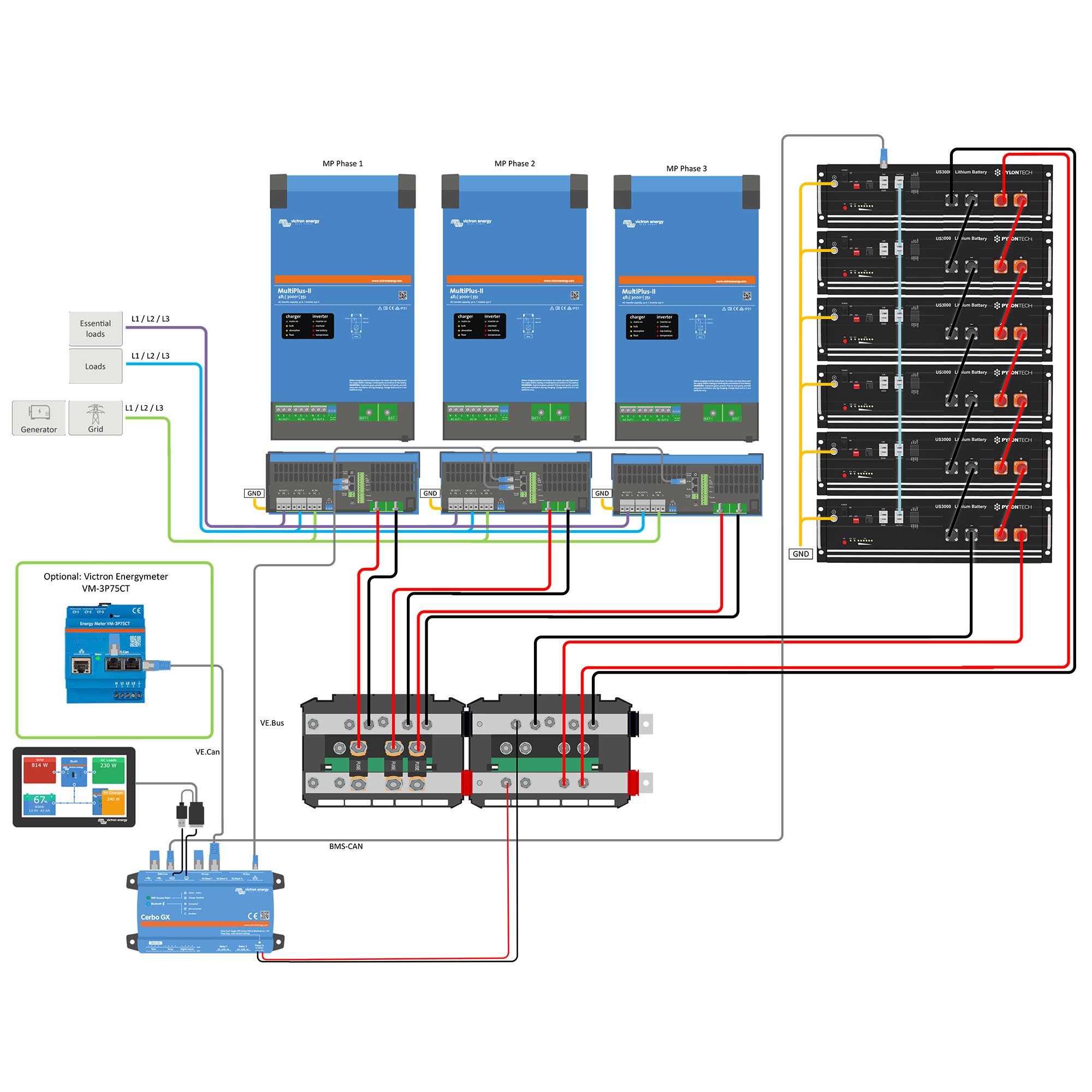
The three-phase configuration is the recommended architecture for this commercial installation. It distributes the loads more evenly across the inverter capacity, provides three-phase output for any future three-phase equipment additions, and scales more gracefully if the load grows further. Power quality requirements for the server room are met by the Multiplus-II’s inverter output: THD below 3 percent, voltage within ±2 percent of 230V, and frequency stability within ±0.1Hz.
Configuration
Continuous
Surge
Three-Phase
Result
Single Multiplus-II 48/5000
5,000VA
9,000VA
No
FAIL — surge
2x parallel 48/5000
7,000VA eff.
18,000VA
No
Acceptable
3x three-phase 48/5000
15,000VA
27,000VA
Yes
Recommended
MPPT Controller Configuration for Large Arrays
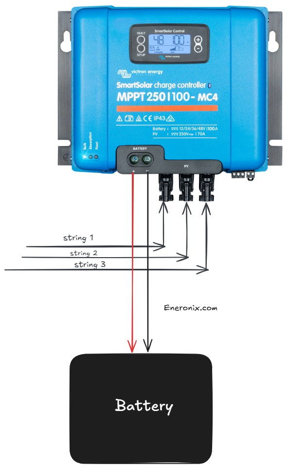
The 30-panel array produces 10,800W of installed capacity across 10 strings of 3 series-connected panels. The correct controller for the commercial system is the Victron SmartSolar MPPT 250/100, which accepts a maximum input voltage of 250V and delivers a maximum output current of 100A to the battery bank, corresponding to 4,800W at 48V. Three MPPT 250/100 controllers manage the 10-string array, with each controller managing 3 strings at 3,600W input:
Controller 1: 3 strings x 1,200W = 3,600W -> within 4,800W limit -> PASS

Controller 2: 3 strings x 1,200W = 3,600W -> within 4,800W limit -> PASS

Controller 3: 3 strings x 1,200W = 3,600W -> within 4,800W limit -> PASS

Cold Voc check per 3S string on MPPT 250/100:

Voc_cold = 3 x 41V x (1 + (-0.0029 x (18-25))) = 125.5V

90% of 250V controller rating = 225V

125.5V < 225V -> PASS with significant margin

Combined derated output: 3 x (3,600W x 0.718) / 48V = 3 x 53.9A = 161.7A total

Combined CCL from 4 BMS units: 400A

161.7A < 400A -> PASS
The MPPT 250/100 provides substantial Voc headroom compared to the residential MPPT 150/60. The 3S string that sat at 83 percent of the MPPT 150/60’s 90-percent voltage limit sits at only 56 percent of the MPPT 250/100’s limit. String configurations up to 6S are technically viable on this controller before the cold Voc limit becomes a constraint, providing significant flexibility for future array expansion.
All three MPPT 250/100 controllers connect to the Cerbo GX via VE.Can. The Cerbo GX receives the CVL and CCL from all four Pylontech BMS units, determines the most conservative values, and distributes them to all three controllers simultaneously. Each controller adjusts its output independently. No synchronisation between controllers is required.
MPPT Controller Configuration Summary:
Controllers -> 3 x Victron SmartSolar MPPT 250/100

Array per controller -> 3 strings of 3S, 3,600W per controller

Combined derated output -> 161.7A total to battery bank

Cold Voc per string -> 125.5V vs 225V limit -> PASS

Combined CCL -> 400A from 4 BMS units -> exceeds array output -> PASS

VE.Can connections -> all three controllers on Cerbo GX VE.Can bus
Complete Off-Grid System Specification
The complete specification for the reference office system consolidates the component selections from Sections 3 through 6 into a single verified specification. Every component has been checked against the system’s requirements using the same constraint verification framework applied to the residential cluster system.
Commercial System Specification — Reference Office:
Solar array -> 27 x 400W panels, 9 strings of 3S (30 with design margin)

MPPT controllers -> 3 x Victron SmartSolar MPPT 250/100

Inverter-charger -> 3 x Victron Multiplus-II 48/5000 (three-phase configuration)

Battery bank -> 16 x Pylontech US3000C (4 groups of 4 units)

BMS units -> 4 x Pylontech BMS

Communication hub -> Victron Cerbo GX + GX Touch 50

CAN adapters -> 4 x VE.Can-to-CAN adapter (one per BMS)

Soft starters -> 3 units: water pump + 2 x air conditioner compressors

DC wiring -> 50mm² battery-inverter per unit, two-constraint framework

AC distribution -> three-phase board, RCBOs per circuit per phase, Type 2 SPD
Parameter
Requirement
Provided
Result
Daily energy demand
42,430Wh
47,385Wh derated harvest
PASS
Usable battery capacity
47,380Wh min
51,120Wh
PASS
Battery autonomy
2 days
2.40 days
PASS
Daily DoD
< 80%
41.7%
PASS
Inverter surge (Phase C)
7,717W
9,000VA per phase
PASS
MPPT Voc per string
< 225V
125.5V
PASS
MPPT combined output
161.7A
300A rated
PASS
The capital cost comparison between the commercial and residential systems illustrates the scaling relationship:
Component
Residential (Posts #1-12)
Commercial (Post #16)
Solar panels
6 x 400W = ₦840,000
27 x 400W = ₦3,780,000
MPPT controllers
1 x 150/60 = ₦320,000
3 x 250/100 = ₦1,440,000
Inverter-charger
1 x 48/3000 = ₦680,000
3 x 48/5000 = ₦3,900,000
Battery bank
4 x US3000C = ₦2,800,000
16 x US3000C = ₦11,200,000
Communication
Cerbo GX = ₦280,000
Cerbo GX + 4 adapters = ₦460,000
Wiring and BOS
₦450,000
₦1,200,000
Installation labour
₦250,000
₦600,000
Total capital cost
₦5,620,000
₦22,580,000
Commercial-Specific Commissioning and Monitoring
The seven-stage commissioning sequence from Post #13 applies to the commercial system without modification, but four additional verification steps are required before handover: three-phase output verification, motor load starting verification, server room power quality verification, and generator phase sequence verification.
Three-Phase Output Verification
After Stage 4 of the commissioning sequence, each phase must be measured independently and confirmed within 1 percent of 230V. The phase angle between phases must be confirmed at 120 degrees ±2 degrees using a power analyser. A phase angle error above 2 degrees indicates a VEConfigure setup error in the master-slave designation and must be corrected before any loads are connected.
Motor Load Starting Verification
Each motor load must be started individually while the other loads are running at their expected simultaneous levels. The AC load reading on the Cerbo GX must be monitored in the seconds around the start event. The load spike produced by the motor starting must be confirmed below the per-phase surge rating of 9,000VA. If the load spike exceeds this figure with the soft starter installed, the soft starter ramp time must be increased until the spike is within the surge rating.
Server Room Power Quality Verification
The AC output feeding the server room distribution circuit must be measured for total harmonic distortion, voltage stability, and frequency stability under full server room load. THD must be confirmed below 3 percent. Voltage must be confirmed within ±2 percent of 230V under load. Frequency must be confirmed within ±0.1Hz. These measurements must be taken with a calibrated power quality analyser and the results recorded in the commissioning documentation.
Generator Phase Sequence Verification
When a three-phase generator is connected to the Multiplus-II AC input, the phase sequence at the generator output terminals must be confirmed to match the phase sequence expected by the three-unit Multiplus-II configuration before the generator is started under load. A reversed phase sequence will cause the Multiplus-II to reject the generator source and remain in inverter mode, which is a common commissioning error on three-phase systems.
Commercial Commissioning Checklist Additions:
Three-phase voltage check -> each phase 230V ±1%, phase angle 120° ±2° at board

Motor starting verification -> AC load spike below 9,000VA per phase with soft starter

Power quality verification -> THD < 3%, voltage ±2%, frequency ±0.1Hz under server load

Generator phase sequence -> confirmed before three-phase generator first start under load

VRM alert additions -> per-phase voltage imbalance > 5%, server cooling temperature

Load profile review at day 30  -> compare actual vs load audit, identify unaudited loads
How does commercial off-grid solar sizing differ from residential?
Three differences drive the calculation. First, commercial buildings have motor loads, water pumps, air compressors, lift motors, with starting surge currents of 5 to 8 times running current. A single 1,500W pump creates a 9,000W surge that a residential methodology would not capture. Second, commercial buildings have 24-hour standby loads, server room cooling, access control, alarm systems that consume energy overnight at a level residential homes do not. Third, autonomy specification is driven by revenue protection rather than comfort, a commercial client can quantify the cost of an outage hour, which sets a higher autonomy standard than residential design.
What inverter architecture is needed for a commercial off-grid system?
For peak surge demands above 9,000W on a single-phase installation, a single Multiplus-II 48/5000 is insufficient. Two options address this: two Multiplus-II 48/5000 units in parallel provide 10,000W continuous and 18,000VA surge capacity on a single phase; three Multiplus-II 48/5000 units in three-phase configuration provide 15,000W continuous and 27,000VA total surge across three phases, which is the correct architecture for a building with significant three-phase motor loads. The choice depends on whether the building has three-phase loads and whether the utility connection, if any, is single or three-phase.
How do I calculate motor starting surge for inverter sizing?
The starting surge current for an induction motor is typically 6 to 8 times the full-load running current. For a 1,500W water pump running at 230V single-phase, the running current is approximately 6.5A. The starting surge current at 6x is approximately 39A equivalent to 8,970W, nearly 9kW of instantaneous surge demand. For inverter sizing, calculate the worst-case scenario: all running loads active simultaneously plus the largest motor load starting. The inverter’s surge rating must exceed this combined figure, or a soft starter must be specified for the motor to reduce the starting current to 2 to 3 times running current.
How many days of autonomy should a commercial off-grid system have?
A minimum of two autonomy days is the standard for a commercial system where outage has a direct revenue cost. Two autonomy days means the battery bank can supply all loads including 24-hour standby loads for 48 hours with no solar input before reaching the minimum discharge threshold. For critical facilities, data centres, medical facilities, telecommunications, three to four autonomy days is more appropriate. The autonomy specification should be agreed with the client as part of the brief, not assumed by the designer.
What is the most commonly missed load in a commercial solar audit?
The 24-hour standby loads are the most consistently missed category. Server room cooling units running continuously at 500W contribute 12,000Wh per day, more than the lighting load for a 10-person office. Access control panels, alarm systems, network switches, and CCTV recorders all draw continuous power. When these loads are not captured in the audit, the overnight battery sizing is insufficient and the system fails to reach morning with adequate charge remaining, which is misdiagnosed as an undersized solar array when the actual problem is an underspecified battery bank.
Can I add a generator backup to a commercial off-grid solar system?
Yes, and for most commercial installations it is recommended. A generator provides insurance against extended overcast periods that exceed the battery bank’s autonomy. For a commercial system, size the generator using the three-demand calculation: peak AC load plus battery charging load divided by 0.80. Set the AC input current limit in the inverter to keep the combined demand within the generator’s safe operating envelope. For three-phase commercial systems the generator must be three-phase and the phase sequence must be verified at commissioning before connecting to the inverter bank.
Conclusion
The water pump that shut down the office system in the introduction was not an unusual load. It was a standard building service that the residential methodology had no category for, because residential load audits do not ask about building infrastructure. The commercial load audit methodology in Section 2 does ask, because the commercial installer’s job is to find every load before the system is energised rather than after the first overload alarm.
The three adjustments that the residential sizing methodology requires for commercial application are straightforward to apply. The load audit must identify all motor loads and their starting surge currents, all standby loads and their 24-hour daily energy contributions, and the peak simultaneous load including the worst-case motor starting scenario. The battery bank must be sized for the overnight standby energy demand in addition to the worst-case overcast day operating deficit. The inverter must be sized for the combined surge demand after soft starters have been applied to all motor loads above 1kW.
Everything else, the array sizing equation, the MPPT controller Voc and output current checks, the battery bank DoD and autonomy calculation, the cable sizing two-constraint framework, the BMS communication architecture, the commissioning sequence — applies to the commercial system without modification. The framework built across Posts #1 through #13 scales from a 6-panel residential installation to a 27-panel commercial one by changing the inputs, not the method.
The commercial system specified in this post costs approximately four times the residential cluster system and serves approximately four times the daily energy demand. Against a commercial generator running cost that scales proportionally with load, the payback period is comparable to the one-year residential payback established in Post #15. The economics of off-grid solar do not deteriorate at commercial scale.
In the next post we examine generator integration in detail: generator selection and sizing, hybrid operating modes, automatic generator start configuration, and the interaction between generator charging and solar charging on the Victron platform.
I am Engr. Ubokobong Ekpenyong, a solar specialist and lithium battery systems engineer with over five years of hands-on experience designing, assembling, and commissioning off-grid solar and energy storage systems. My work focuses on lithium battery pack architecture, BMS configuration, and system reliability in off-grid and high-demand environments.
Contains information related to marketing campaigns of the user. These are shared with Google AdWords / Google Ads when the Google Ads and Google Analytics accounts are linked together.
90 days
__utma
ID used to identify users and sessions
2 years after last activity
__utmt
Used to monitor number of Google Analytics server requests
10 minutes
__utmb
Used to distinguish new sessions and visits. This cookie is set when the GA.js javascript library is loaded and there is no existing __utmb cookie. The cookie is updated every time data is sent to the Google Analytics server.
30 minutes after last activity
__utmc
Used only with old Urchin versions of Google Analytics and not with GA.js. Was used to distinguish between new sessions and visits at the end of a session.
End of session (browser)
__utmz
Contains information about the traffic source or campaign that directed user to the website. The cookie is set when the GA.js javascript is loaded and updated when data is sent to the Google Anaytics server
6 months after last activity
__utmv
Contains custom information set by the web developer via the _setCustomVar method in Google Analytics. This cookie is updated every time new data is sent to the Google Analytics server.
2 years after last activity
__utmx
Used to determine whether a user is included in an A / B or Multivariate test.
18 months
_ga
ID used to identify users
2 years
_gali
Used by Google Analytics to determine which links on a page are being clicked
30 seconds
_ga_
ID used to identify users
2 years
_gid
ID used to identify users for 24 hours after last activity
24 hours
_gat
Used to monitor number of Google Analytics server requests when using Google Tag Manager
1 minute
You can find more information in our Cookie Policy and .


")


")
")

")

