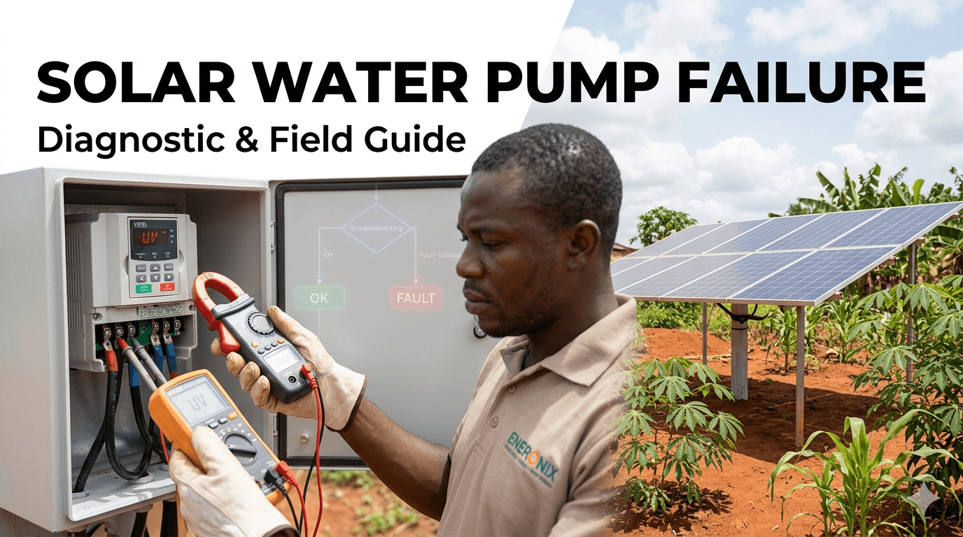
Common Solar Water Pump Failures and How to Diagnose Them

A solar water pump system that stops working is not just an inconvenience. For a rural household, a farm, or a community water point in Nigeria, it can mean no water for cooking, no water for livestock, and no water for crops during the most critical periods of the year.
Most failures are diagnosable without specialised equipment. You need a multimeter, a clamp meter, basic hand tools, and a methodical approach. The goal of this guide is to give any competent installer or technically minded owner the ability to identify which component has failed and why, without unnecessarily pulling the pump from the borehole or replacing components that are still working.
This guide is structured by symptom. Find what your system is doing (or not doing) and follow the diagnostic path to the root cause.
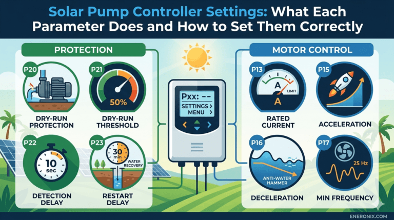
This is the final post in the Eneronix Solar Water Pumping series. For the complete series starting point, see: Solar Water Pump System in Nigeria. For controller parameter settings that prevent most of the failures covered in this guide, see: Solar Pump Controller Settings: What Each Parameter Does.
Before You Diagnose Anything: The Four Safety Checks
Follow these four steps before touching any component in a solar pump system. These protect you from electric shock and prevent you from making damage worse.
- Isolate the solar array. Disconnect the array cables from the VFD or controller input terminals, or open the DC isolator switch if one is installed. Solar panels generate voltage whenever light hits them. There is no off switch for the panels themselves.
- Isolate the pump motor. Disconnect the drop cable from the VFD output terminals before handling any pump, cable, or borehole component.
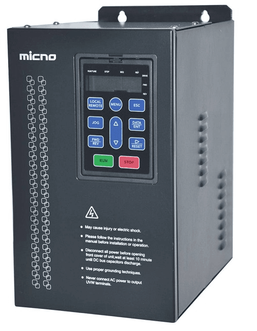
- Discharge the VFD capacitors. After disconnecting both input and output, wait at least 5 minutes before opening the VFD enclosure. VFD internal capacitors hold dangerous voltage after disconnection. Some models have a discharge indicator LED.
- Verify dead with a multimeter. Measure voltage at the VFD input and output terminals before touching internal components. Confirm zero volts before proceeding.
DC voltage from solar arrays is more dangerous than Nigerian grid AC in one specific way: it does not naturally cross zero volts, which means DC arcs sustain themselves rather than self-extinguishing. A DC arc at 200V will continue burning until you physically separate the contacts or the source is exhausted. Always isolate the array before working on any part of the system.
Diagnostic Tools You Need

| Tool | What It Measures | Why You Need It |
| Digital multimeter (DMM) | DC voltage, AC voltage, resistance, continuity | Essential. Diagnoses panel output, wiring faults, motor winding resistance, and controller input/output. |
| Clamp meter (AC/DC) | AC and DC current without breaking the circuit | Measures running current of the motor without disconnecting wires. Essential for identifying overload and dry-run conditions. |
| Insulation resistance tester (megohmmeter) | Insulation resistance of motor windings and cable | Identifies motor winding breakdown before it becomes a complete failure. A must-have for any serious pump technician. |
| Flat screwdrivers and Torx/Phillips set | Mechanical access | Opening controller enclosures, tightening terminals, accessing junction boxes. |
| Non-contact voltage tester (tic tracer) | Presence of AC voltage without contact | Quick safety check before working on AC wiring. |
| Pipe pressure gauge (0 to 10 bar) | Water pressure at pump outlet | Diagnoses blocked pipes, incorrect pump sizing, and head-related issues without pulling the pump. |
The same diagnostic tools and measurement methodology used for solar pump troubleshooting apply to general off-grid system commissioning. See: Off-Grid Solar System Commissioning and Troubleshooting Guide.
Failure Category 1: Pump Does Not Start
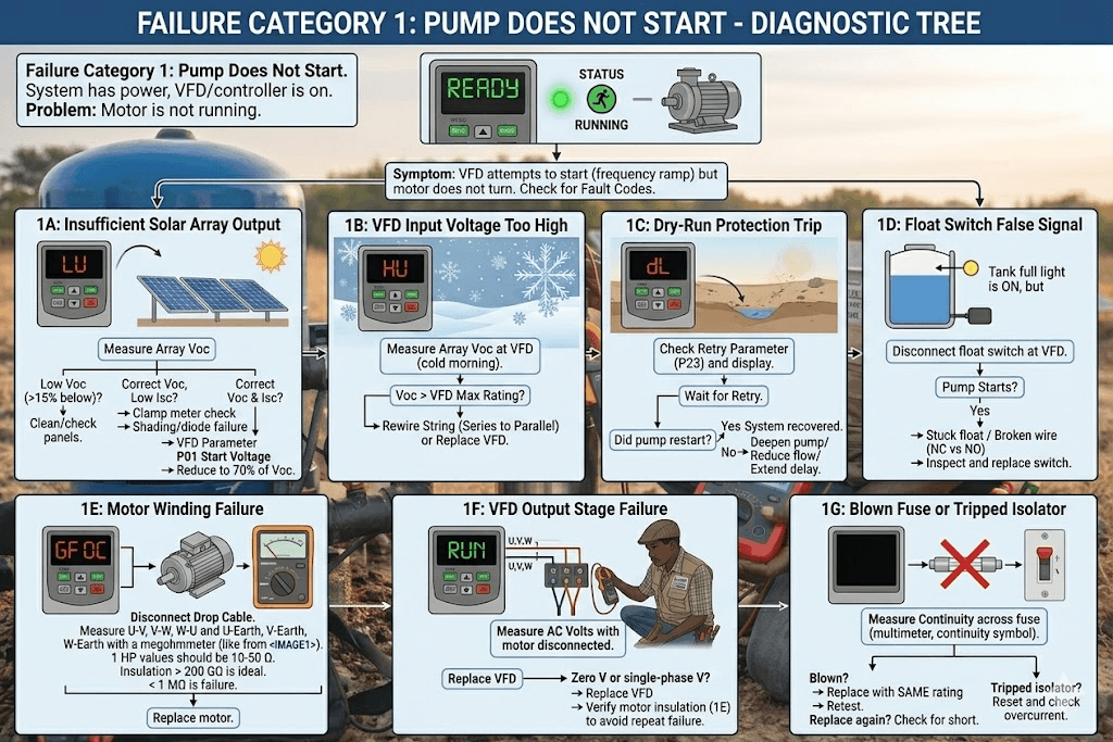
The most common complaint. The system has power and the controller is on, but the pump motor does not run. There are seven distinct causes, each with a clear diagnostic path.
Cause 1A: Insufficient Solar Array Output

Symptom: VFD display shows low input voltage or undervoltage fault. Pump does not attempt to start. Often occurs on cloudy mornings or heavily dusty panels.
Diagnosis:
- Measure DC open-circuit voltage (Voc) at the VFD input terminals with the VFD disconnected. Compare to expected string Voc from the panel datasheet.
- If Voc is correct but pump still will not start, measure DC current (Isc) with a clamp meter at the array positive cable under good sunlight conditions. Compare to expected string Isc.
- If both Voc and Isc are within 10 per cent of expected, the panels are producing correctly. The problem is the minimum start voltage parameter being set too high.
- Array Voc more than 15 per cent below expected: check for shading, soiled panels, disconnected panel, or failed bypass diode in a junction box.
- Array Voc correct but Isc significantly low: partial shading on one panel, or a failed panel that is producing voltage but not current.
- Array output correct, pump still will not start: reduce minimum start voltage parameter (P01) to 70 per cent of Voc and retest.
For a full treatment of how to verify solar panel output in the field, including the Voc and Isc measurement method, see: Solar Panel Shading Losses in Nigeria.
Cause 1B: VFD Input Voltage Too High (Overvoltage Fault)
Symptom: VFD shows overvoltage fault on startup. Usually occurs on cold, clear mornings in harmattan season when panel Voc is at its maximum.
Diagnosis:
- Measure array Voc at the VFD input terminals on a cold morning (before 9 AM, below 25 degrees ambient).
- Compare to VFD rated maximum input voltage from the datasheet.
- If measured Voc exceeds VFD maximum, the array is overvoltage for this controller.
Fix: Rewire one panel from series to parallel to reduce string voltage. If this is not possible with the current array configuration, replace the VFD with one rated for a higher maximum input voltage. Do not attempt to shade panels to reduce voltage. This is not a safe or reliable long-term solution.
Cause 1C: Dry-Run Protection Trip with Long Retry Delay
Symptom: System ran previously but pump is now silent. VFD display may show dry-run or underload fault. Controller is in retry waiting period.
Diagnosis:
- Check the VFD display for a fault code. Most controllers display the last fault when idle.
- Check the retry delay parameter (P23). If set to 30 to 60 minutes, the controller may simply be waiting to retry.
- Wait for the retry interval to expire. If the pump starts and runs normally, the borehole dry-ran and has recovered.
- If the pump dry-runs again at retry, the borehole water table is genuinely low. Check the season (dry season water table drop is normal in northern Nigeria).
A dry-run trip during harmattan dry season in northern Nigeria is expected behaviour, not a failure. The borehole is protecting itself. Do not lower the dry-run threshold to avoid these trips. Fix the underlying cause: either deepen the pump setting, reduce daily draw rate, or extend the retry delay.
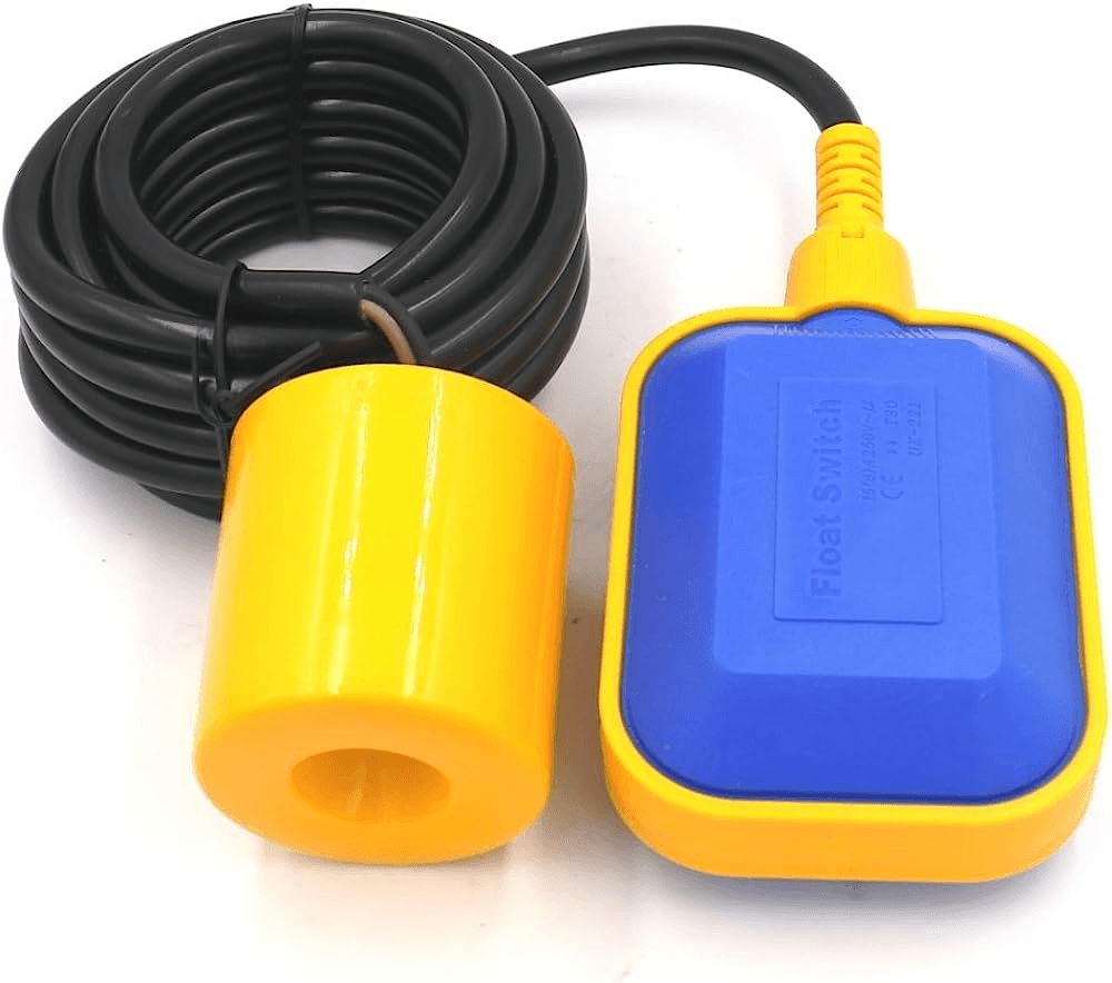
Cause 1D: Float Switch Falsely Signalling Tank Full
Symptom: Controller powers up, displays normal, but pump does not start. No fault code. Tank is clearly not full.
Diagnosis:
- Disconnect the float switch cable from the VFD control terminals.
- If the pump immediately starts after disconnection, the float switch is falsely signalling a full tank.
- Inspect the float switch: check if the float mechanism is stuck in the up (full) position. Physically depress and release the float. Check for scale, debris, or corrosion jamming the mechanism.
- Check float switch terminal connections at the VFD. A Normally Closed switch with a broken wire sends an open-circuit signal that the VFD interprets as tank full.
For float switch wiring configurations and how incorrect NC vs NO wiring causes this fault, see the P30 section of: Solar Pump Controller Settings: What Each Parameter Does.
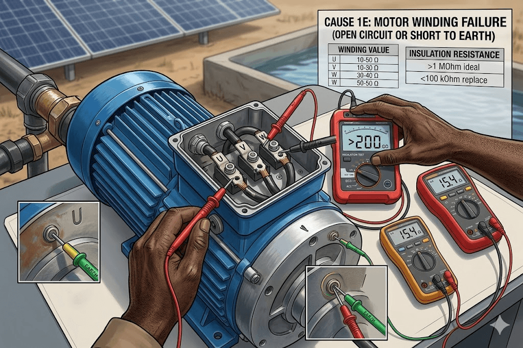
Cause 1E: Motor Winding Failure (Open Circuit or Short to Earth)
Symptom: VFD attempts to start (display shows starting frequency ramping) but motor does not turn. VFD may immediately trip on overcurrent or ground fault.
Diagnosis:
- Disconnect the drop cable from the VFD output terminals.
- At the top of the borehole, disconnect the three motor cable conductors from the drop cable.
- Measure resistance between each pair of motor terminals (U-V, V-W, W-U). For a 1HP motor, expect 10 to 50 ohms between each pair. Values should be approximately equal across all three pairs. An open circuit (infinite resistance) on any pair means a broken winding.
- Measure resistance from each motor terminal to the motor casing (earth). Expect 100 MOhm or higher. Any reading below 1 MOhm indicates insulation breakdown. Below 100 kOhm means the motor is shorted and must be replaced.
If motor insulation resistance is below 1 MOhm, do not reconnect the motor to the VFD. Running a motor with degraded insulation will cause a phase-to-earth fault that can damage the VFD output stage. Test insulation resistance before every reconnection after a fault event.
Cause 1F: VFD Output Stage Failure
Symptom: Array produces correct voltage and power. Motor windings test good. VFD powers up and displays normally. But when a start is commanded, no voltage appears at the VFD output terminals.
Diagnosis:
- With the motor disconnected, command the VFD to start and measure AC voltage at the U, V, W output terminals with a multimeter set to AC. A working VFD should produce variable AC voltage that increases as frequency ramps up.
- Zero volts on all three output terminals while the VFD shows a running state indicates a failed output IGBT stage.
- Voltage on only two of three terminals indicates one IGBT phase has failed.
A failed VFD output stage is not field-repairable. The VFD must be replaced. Before replacing, verify the motor insulation resistance (step 1E above) to confirm the motor failure did not cause the VFD failure, or vice versa. A shorted motor can destroy VFD output transistors. A failed VFD output can cause motor winding stress. Both should be tested before reconnecting.
Cause 1G: Blown DC Input Fuse or Tripped DC Isolator
Symptom: VFD display is completely dark. No response to any control input.
Diagnosis:
- Check the DC surge protection device and any in-line DC fuse between the array and VFD. Measure continuity across the fuse with a multimeter. No continuity means a blown fuse.
- Check the DC isolator switch position. It may have tripped to the off position due to overcurrent.
- Measure Voc at the array positive and negative cables before the fuse. If array voltage is present but VFD shows no power, the fuse or isolator is the break point.
Replace the fuse with one of the same rating. Do not upsize the fuse. The fuse rating is a protection limit, not a starting point. If the fuse blows again immediately on replacement, there is a wiring fault or a failed VFD input stage causing a short circuit. Investigate before replacing again.
Failure Category 2: Pump Runs but Produces No Water or Very Little Water
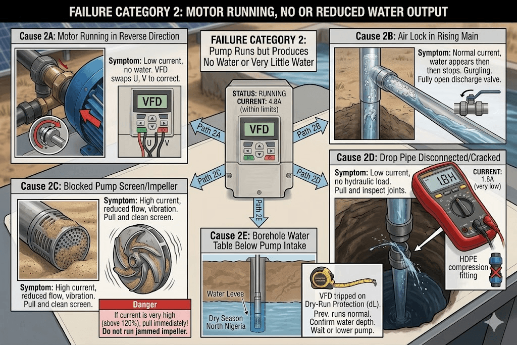
The motor is running (current draw confirmed, VFD shows running state) but little or no water comes out of the delivery pipe. This category has distinct causes depending on whether water output is zero or just reduced.
Cause 2A: Motor Running in Reverse Direction
Symptom: Motor runs quietly, current draw is low (near no-load), no water delivered. This is the most commonly overlooked cause of a new installation producing no water.
An AC three-phase motor runs in the direction determined by the phase sequence of its supply. If any two of the three output cables are swapped during installation, the motor spins backwards. A centrifugal submersible pump spinning backwards develops almost no head and very little flow.
Diagnosis: With the pump at the surface (before installation into the borehole), observe the motor shaft rotation direction and compare to the direction arrow on the pump body. Alternatively, command a brief start and listen: a motor running in reverse sounds different (higher pitched hum, less mechanical noise) from one running correctly.
Fix: Swap any two of the three motor output cables at the VFD output terminals (U, V, W). Retest. Always verify rotation direction at the surface before lowering into the borehole.
Cause 2B: Air Lock in the Rising Main
Symptom: Motor runs with normal current draw. Water appears briefly at startup then stops. Rising main may vibrate or gurgle.
An air lock occurs when air is trapped in the rising main pipe, preventing water from flowing. Common in new installations or after any pipe work that allowed air to enter the system.
Diagnosis: Open the discharge valve fully and allow the pump to run for 2 to 5 minutes. Properly sealed rising main with a functioning foot valve should purge air within 2 minutes. If gurgling continues beyond 5 minutes, the air entry point has not been sealed.
Check: the check valve at the pump outlet (prevents backflow when pump stops), the foot valve if present, and all pipe joints above the pump for air ingress points.
Cause 2C: Blocked or Clogged Pump Screen or Impeller
Symptom: Motor current draw is higher than normal. Pump vibrates more than usual. Water output is reduced but not zero. Pressure at outlet is lower than expected.
Sand, gravel, or debris in the borehole can partially block the pump intake screen or jam the impeller. This is more common in newly developed boreholes and in northern Nigerian sandy aquifers.
Diagnosis:
- Measure motor current with a clamp meter. Compare to normal running current from commissioning records. Current significantly above rated indicates mechanical overload from a blocked impeller.
- If current is very high (above 120 per cent of rated) and the pump is making grinding or rattling noise, pull the pump immediately. Running a jammed impeller will burn out the motor within minutes.
- If current is mildly elevated and water flow is reduced but present, the screen is partially blocked. Allow the pump to run at a lower flow setting (reduce VFD frequency to 35 to 40 Hz) for 30 minutes to attempt to self-clear. If not resolved, pull the pump.
Never continue running a pump with abnormally high current draw. The motor is under mechanical stress and will overheat. A three-minute delay costs nothing. A burned-out motor in a 60-metre borehole costs tens of thousands of naira to replace.
Cause 2D: Drop Pipe Disconnected or Cracked Inside Borehole
Symptom: Motor runs with low current (unloaded). No water at delivery outlet. No sound of water movement in the pipe.
If the drop pipe joint has separated inside the borehole, the pump is pushing water back into the borehole rather than up to the surface. The motor runs without hydraulic load, drawing minimal current.
Diagnosis: Measure motor current at the clamp meter. If current is 30 to 50 per cent of rated running current with no water at outlet, the pump has lost its hydraulic load. Pull the pump and rising main carefully. Inspect every pipe joint. The joint that separated will be obvious.
Prevention: Use properly rated HDPE compression fittings rated for submersible pump pressure. Verify all joints before lowering into borehole. Never use push-fit fittings for any buried or submerged pipe joint.
Cause 2E: Borehole Water Table Below Pump Intake
Symptom: VFD has tripped on dry-run protection. Motor not running. Previous runs were normal.
The borehole water level has dropped below the pump intake. This is a seasonal and situational occurrence in Nigeria, most common in North-West and North-East states between January and March.
Diagnosis: This is confirmed by the dry-run trip. The pump is correctly protecting itself. Verify by lowering a weighted rope or measuring tape into the borehole alongside the drop cable and measuring the current water depth.
If the water table has dropped permanently (not seasonal), the pump setting depth must be increased. This means pulling the pump, adding more drop pipe and cable, and reinstalling at a greater depth. If the water table has simply dropped seasonally, reduce daily pumping volume, increase the dry-run retry delay, and wait for the water table to recover after the rains return.
For correct pump setting depth calculation with seasonal water table buffer, see: How to Size a Solar Submersible Pump for a Borehole in Nigeria.
Failure Category 3: Pump Runs Intermittently or Cycles On and Off
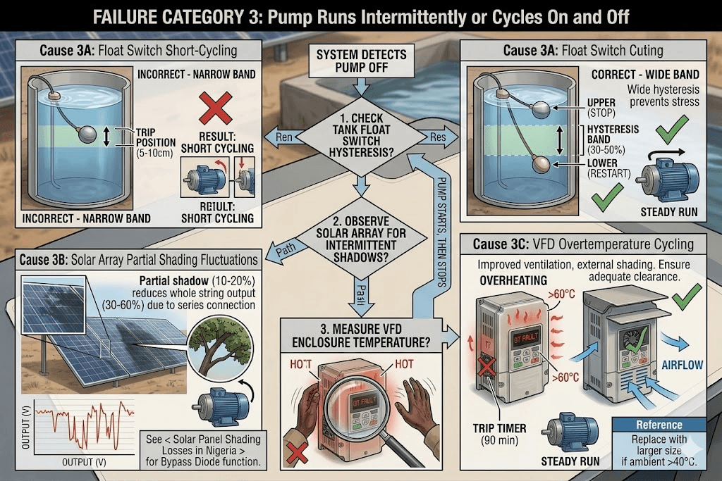
Cause 3A: Float Switch Short-Cycling
Symptom: Pump starts, runs for 30 seconds to 5 minutes, stops, restarts shortly after. Repeats continuously. Tank is neither full nor empty.
The float switch is positioned at a level where it trips on and off repeatedly as minor water level fluctuations occur. This is called short-cycling and it stresses the motor every startup.
Diagnosis: Observe the float switch behaviour directly inside the tank. The float should have clear distinction between its trip-up (full) position and its reset-down (resume pumping) position. If both positions are within 5 to 10 cm of each other, there is insufficient hysteresis.
Fix: Fit a second float switch below the first, wired as a separate start signal. The upper float stops the pump when full. The lower float restarts the pump only when the level drops by 30 to 50 per cent. This creates a wide hysteresis band that eliminates short-cycling.
Cause 3B: Solar Array Output Fluctuating Due to Partial Shading
Symptom: Pump starts when sun is strong, stops when a cloud passes, restarts when sun returns. Cycles repeatedly throughout the day. Normal behaviour on intermittently cloudy days but excessive on clear days.
On a genuinely clear day, if the pump is cycling due to apparent solar fluctuation, the cause is usually partial shading from a nearby object (tree branch, building edge, antenna) that intermittently covers one panel in the array.
Diagnosis: Observe the array at the time when cycling occurs. Identify any intermittent shadow crossing any panel. Even partial shading of 10 to 20 per cent of one panel in a series string can reduce the entire string output by 30 to 60 per cent due to the series connection.
For a detailed explanation of why partial shading on one panel in a string affects the entire array output, and what bypass diodes do to mitigate this, see: Solar Panel Shading Losses in Nigeria.
Cause 3C: VFD Overtemperature Cycling
Symptom: Pump runs for a consistent period (30 to 90 minutes) then trips. After a cooling period it restarts. Trips again after the same duration. Pattern repeats all day.
The VFD is reaching its thermal protection limit and tripping on overtemperature (OT fault). After cooling, it restarts. The consistent run time before tripping is the thermal time constant of the VFD.
Diagnosis: Check VFD temperature by feeling the heatsink fins on the outside of the enclosure. If uncomfortably hot to touch (above 60 degrees C), the VFD is thermally stressed. Check enclosure ventilation: the fan must be running, ventilation slots must not be blocked, and there must be adequate clearance above and below the VFD for airflow.
Fix: Improve ventilation. Add a shading cover above the enclosure to reduce direct sunlight heating. If ambient temperature exceeds 40 degrees C consistently, replace the VFD with a unit one size larger. A larger VFD running the same motor generates less heat because it operates further below its rated capacity.
Failure Category 4: Pump Runs but Trips Frequently on Fault Codes
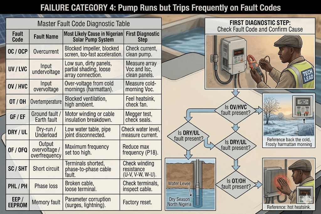
Master Fault Code Diagnostic Table
| Fault Code | Fault Name | Most Likely Cause in Nigerian Solar Pump System | First Diagnostic Step |
| OC / OCP | Overcurrent | Acceleration time too short. Array undersized for motor. Blocked impeller. | Increase acceleration time to 10-15 sec. Check array output voltage and current. |
| UV / LVC | Input undervoltage | Solar irradiance too low. Dirty panels. Partially shaded array. Loose array connection. | Measure array Voc and Isc. Clean panels. Inspect all cable connections. |
| OV / HVC | Input overvoltage | Array Voc exceeds VFD maximum. Cold morning in harmattan with high Voc. | Measure cold-morning array Voc. Compare to VFD maximum input voltage rating. |
| OT / OH | Overtemperature | VFD enclosure too hot. Blocked ventilation. Ambient above 45 degrees C. | Check heatsink temperature. Inspect ventilation fan and airflow slots. |
| GF / EF | Ground fault / Earth fault | Motor winding insulation breakdown. Water ingress into motor terminal box or cable joint. | Megger test motor insulation resistance. Inspect motor cable entry seal. |
| DRY / UL | Dry-run / Underload | Borehole water table below pump. Pipe joint disconnected inside borehole. | Check season and expected water table. Measure motor current at clamp meter. |
| OF / OFQ | Output overvoltage / overfrequency | Maximum output frequency set too high. Motor overspeeding. | Check P18 (max frequency). Reduce to 50 Hz. |
| SC / SHT | Short circuit | Motor terminals shorted. Phase-to-phase fault in drop cable. | Disconnect motor from VFD. Measure resistance between motor terminals U-V, V-W, W-U. |
| PHL / PH | Phase loss (3-phase only) | One motor cable conductor open circuit. Loose terminal at VFD output or motor. | Check terminal tightness at VFD output. Inspect drop cable for damage. |
| EEP / EEPROM | Memory fault | VFD parameter memory corrupted. Usually after power surge or lightning. | Perform factory reset. Re-enter all parameters from commissioning record. |
Failure Category 5: Water Quality Problems Traced to the Pump System
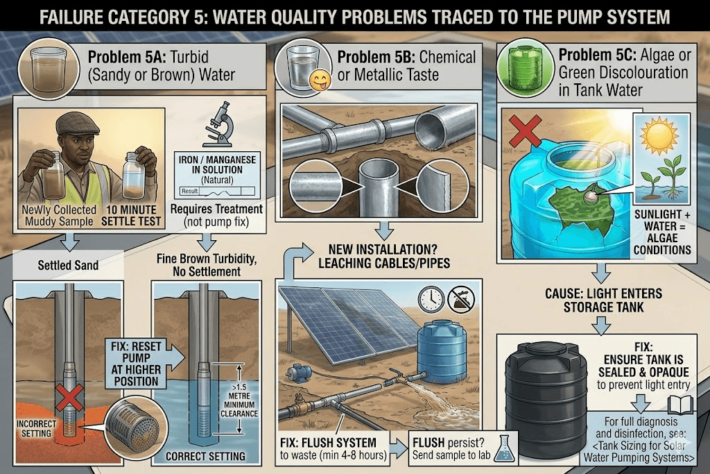
Not all pump system failures are electrical or mechanical. Some failures show up as water quality problems that trace back to the pump, borehole, or tank.
Problem 5A: Turbid (Sandy or Brown) Water
Cause: Sand or sediment being drawn into the pump. Common in newly developed boreholes or after a drop in the borehole water level that brings the pump close to the sediment layer.
Diagnosis: Collect water in a clear container and allow to settle for 10 minutes. Visible sediment settling out confirms sand ingestion. Fine brown turbidity that does not settle may indicate iron-rich water rather than sand.
- If sediment: check pump setting depth. Pump may be too close to the borehole bottom. Pull pump and reset at a higher position leaving at least 1.5 metres between the pump intake and the borehole bottom.
- If fine non-settling turbidity: this is typically iron or manganese in solution, a natural water quality issue not related to the pump. Requires water treatment, not pump adjustment.
Problem 5B: Water Has Chemical or Metallic Taste
Cause in a new installation: the pump, drop pipe, or borehole casing material is leaching into the water. Galvanised steel casing or pipes that have not been flushed can release zinc into the water in the first weeks of operation.
Fix: Flush the system by running the pump to waste (bypass the tank) for 4 to 8 hours on first startup. Most borehole development guidelines recommend a minimum 4-hour flush before connecting to supply. If taste persists after flushing, send a water sample for laboratory analysis. This is good practice for any new borehole installation regardless of taste.
Problem 5C: Algae or Green Discolouration in Tank Water
Cause: Light entering the storage tank, providing conditions for algae growth. Not related to the pump itself, but the tank that follows it in the system.
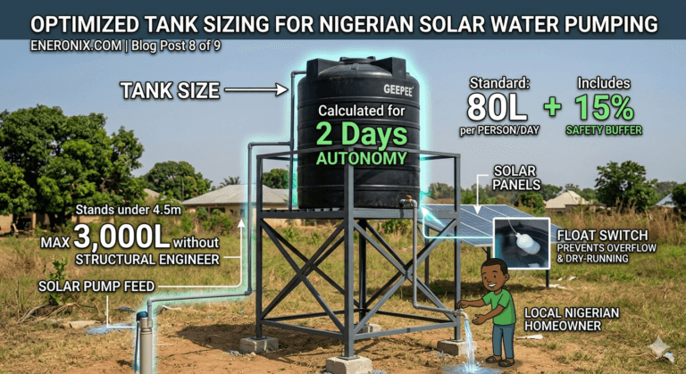
For the full diagnosis and treatment of algae in storage tanks and how to prevent it in Nigerian conditions, see: Tank Sizing for Solar Water Pumping Systems which includes the complete tank disinfection procedure.
Failure Category 6: VFD Display Shows Normal but System Performance Has Degraded
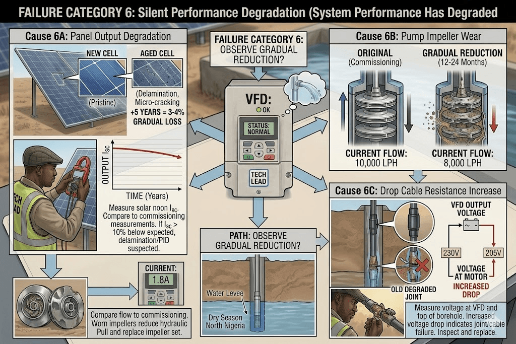
These are the silent failures. No fault codes, no obvious problems, but the system is delivering less water than it should. These failures are the hardest to diagnose because the system appears to be working.
Cause 6A: Panel Output Degradation
Solar panels lose approximately 0.5 to 0.8 per cent of rated output per year due to cell degradation. Over five years, a panel may produce 3 to 4 per cent less than when installed. This is gradual and virtually invisible without measurement.
Diagnosis: Measure array Isc at solar noon on a clear day. Compare to the original commissioning measurement or to the panel’s rated Isc from the datasheet. A panel producing more than 10 per cent below its rated Isc at the same irradiance level has experienced above-normal degradation. Possible causes include delamination, micro-cracking (from poor installation or thermal cycling), or PID (Potential Induced Degradation) in poorly earthed arrays.
For the Nigerian-specific degradation factors and what causes accelerated panel aging in tropical conditions, see: Solar Panel Degradation in Nigeria: How Much Output Do You Lose Over 10 Years?.
Cause 6B: Pump Impeller Wear
Symptom: System runs normally, flow rate has gradually reduced over 12 to 24 months. No fault codes. Motor current is normal or slightly below rated.
Over time, sand and abrasives in borehole water wear the pump impellers. Worn impellers produce less head and flow at the same motor speed. The degradation is gradual and easy to overlook.
Diagnosis: Compare current water output (litres per hour at a measured flow point) to the original commissioning output measurement. A reduction of more than 20 per cent over 24 months indicates significant wear. Also compare motor running current: worn impellers reduce hydraulic load, causing current to drop slightly below original running current.
Fix: Pull the pump and inspect impellers. Many submersible pumps have replaceable impeller stacks. Replacing the impeller set (rather than the entire pump) is significantly more cost-effective. For high-sand Nigerian boreholes, select pumps with stainless steel impellers in the first place.
Cause 6C: Drop Cable Resistance Increase
Symptom: Motor runs, water flows, but pump seems to work harder than before (slightly higher current) for the same output. Voltage at motor terminals is lower than expected.
Over time, water ingress into cable joints or corrosion at crimp connections increases the resistance of the drop cable. Higher cable resistance means more voltage is lost in the cable, less reaches the motor, and the motor draws more current to compensate.
Diagnosis: Measure voltage at the VFD output terminals and at the motor terminals (at the top of the borehole where the cable exits). The difference is the cable voltage drop. Compare to the original commissioning measurement. An increase in voltage drop over time indicates increasing cable resistance.
Fix: Inspect and reseal all cable joints. Replace any joint that shows moisture ingress or corrosion. For cable runs where the entire drop cable has increased resistance, the cable must be replaced.
When to Pull the Pump: Decision Framework
Pulling a submersible pump from a borehole is time-consuming, risks pipe joint damage, and costs N20,000 to N60,000 in labour for a typical residential borehole. Do not pull unless the evidence clearly requires it.
| Pull the Pump | Do NOT Pull the Pump (Diagnose First) |
| Motor insulation resistance below 1 MOhm confirmed by megger test | VFD fault code appears without motor testing done |
| Motor running in reverse direction confirmed at surface before installation | Float switch suspected of causing pump not to start |
| Impeller wear confirmed by 20%+ flow reduction over 12 to 24 months | Intermittent cycling that may be float switch or shading issue |
| Sandy or turbid water confirmed as sand ingestion, not iron content | Overtemperature trip that may be VFD enclosure cooling issue |
| Rising main pipe joint disconnection confirmed by near-zero current and no water | Dry-run trip during dry season (likely seasonal water table drop) |
| Pump confirmed running backwards after installation in borehole | Output reduction that has not been verified by flow measurement |
A submersible pump pulled from a borehole unnecessarily is exposed to mechanical stress during extraction and reinstallation. Every pull introduces risk of pipe joint damage, cable damage, and borehole wall disturbance. Diagnose thoroughly before committing to a pull.
Preventive Maintenance Schedule for Nigerian Solar Pump Systems
Most pump failures are preventable. This schedule addresses the most common failure modes in Nigerian conditions: dust, heat, dry-run events, and electrical degradation.
| Frequency | Task | Why It Matters in Nigeria |
| Weekly (harmattan season) | Clean solar panels | Harmattan dust causes 25-35% output loss within 2 weeks. Regular cleaning maintains pump start reliability. |
| Monthly | Inspect VFD enclosure ventilation. Check heatsink temperature during operation. | Nigerian ambient temperatures accelerate thermal stress on VFD components. |
| Monthly | Test float switch function manually | Float switches in outdoor tank environments can seize due to scale, algae, or insect activity. |
| Quarterly | Inspect all DC cable connections and terminals. Retorque all terminal screws. | Thermal expansion cycles loosen terminals. Loose terminals cause arcing and resistance heating. |
| Quarterly | Record motor running current with clamp meter. Log against original commissioning value. | Trending current over time reveals impeller wear and cable degradation before they become failures. |
| Quarterly | Inspect DC surge protection device. Replace if indicator shows fault. | Nigerian lightning strike frequency is high. A sacrificed SPD means your VFD is unprotected until replaced. |
| 6-Monthly | Clean and disinfect storage tank. | Bacterial and algae contamination accumulates. Clean tank prevents waterborne illness. |
| 6-Monthly | Measure array Isc and Voc at solar noon on a clear day. Log against original commissioning values. | Identifies panel degradation and partial failures before they cause system underperformance. |
| Annually | Test dry-run protection with discharge valve closure method. | Confirms the primary motor protection is functional. Motor burnout from undetected dry-run is the most expensive failure mode. |
| Annually | Perform motor insulation resistance test (megger test). | Identifies motor winding degradation before it becomes a complete failure or causes VFD damage. |
| Every 3 years | Inspect pump and rising main for scale and biological growth. Descale if needed. | Calcite and iron scale deposits reduce pipe bore and pump efficiency in high-mineral Nigerian groundwater. |
Complete Diagnostic Quick-Reference: Symptom to Root Cause
| Symptom | Most Likely Root Cause | First Action |
| Pump does not start. VFD dark. | Blown DC fuse or dead VFD power supply. | Check DC fuse continuity. Measure array voltage at VFD input terminals. |
| Pump does not start. VFD on. UV fault displayed. | Insufficient solar irradiance or dirty panels. | Clean panels. Measure array Voc and Isc. |
| Pump does not start. VFD on. No fault code. | Float switch falsely signalling tank full. | Disconnect float switch from VFD terminals. Retest. |
| Pump does not start. VFD shows OV / overvoltage fault. | Array Voc exceeds VFD maximum input voltage. | Measure cold-morning Voc. Compare to VFD rating. |
| Pump runs. Motor hums. No water. | Motor running in reverse direction. | Swap any 2 motor cables at VFD output terminals. Test rotation direction. |
| Pump runs. Normal current. Reduced water flow. | Blocked pump screen. Worn impellers. Partial pipe blockage. | Measure flow rate. Check current vs rated. Pull pump if flow reduced by 20%+. |
| Pump runs. Low current (50% of rated). No water. | Rising main pipe joint disconnected inside borehole. | Confirm low current with clamp meter. Pull pump. Inspect all pipe joints. |
| Pump cycles on and off every few minutes. | Float switch short-cycling or partial array shading. | Observe float switch and check for intermittent shading on array. |
| Pump trips after 30-90 minutes then restarts. | VFD overtemperature. Enclosure too hot. | Check heatsink temperature. Improve ventilation and shading of enclosure. |
| Pump trips on dry-run regularly in dry season. | Seasonal water table drop. Normal protective behaviour. | Extend retry delay. Reduce daily draw rate. Wait for rainy season recovery. |
| Motor trips on GF / ground fault. | Motor insulation breakdown or water ingress into cable. | Megger test motor insulation resistance. Inspect cable entry seals. |
| Water output declining over 12-24 months. No faults. | Impeller wear or panel degradation. | Measure flow rate and compare to commissioning. Measure array Isc. |
| Sandy or turbid water. | Sand ingestion. Pump too close to borehole bottom. | Collect water sample. Confirm sand settling. Pull pump and reset higher in borehole. |
| System working but VFD overheating daily. | Undersized VFD for Nigerian climate. Thermal derating needed. | Replace with next size up VFD. Improve enclosure ventilation. |
Summary
Solar pump failures in Nigeria follow predictable patterns. Dry-run damage from harmattan water table drops. Motor burnout from undersized arrays that cannot sustain a clean startup. VFD failures from thermal stress in unventilated enclosures. Float switch failures from outdoor exposure. Panel performance loss from harmattan dust.
Every one of these failures is diagnosable with a multimeter, a clamp meter, and a systematic approach to elimination. Every one of them is also preventable with the right initial system design, correctly set controller parameters, and a consistent maintenance schedule.
The most expensive pump failures in Nigeria are not caused by bad equipment. They are caused by the absence of dry-run protection, incorrectly set controller parameters, and the lack of a commissioning record to compare against when something goes wrong.
This guide completes the Eneronix Solar Water Pumping and Agri-Solar cluster. Every post in this series is linked from the pillar post and from the relevant sections of each supporting post.
Return to the start of the series: Solar Water Pump System in Nigeria: How It Works, What It Costs, and How to Size One.
Frequently Asked Questions
Q1: How do I know if my solar pump motor is burned out or just tripped?
A tripped motor (VFD protection activated) will restart when conditions are correct. The VFD display shows a fault code. A burned-out motor will not respond regardless of the power supply. To confirm motor condition: disconnect the drop cable from the VFD output, measure resistance between motor terminals U-V, V-W, and W-U. If any pair shows open circuit (infinite resistance), the winding is burned out. Also measure insulation resistance from each terminal to earth. Below 1 MOhm confirms winding insulation failure.
Q2: My solar pump is producing half its normal water output. The VFD shows no fault. What should I check first?
Check in this order: first, clean the solar panels and measure array output at solar noon to confirm full power is available. Second, measure motor running current with a clamp meter and compare to the original commissioning current. Third, measure water flow rate at the delivery point and compare to original commissioning flow. If current is normal but flow is reduced, the problem is in the hydraulics (impeller wear, partial pipe blockage). If current is below normal and flow is reduced, the pump is not receiving full hydraulic load (check for disconnected pipe joint or reverse rotation).
Q3: Can I repair a burned-out submersible pump motor in Nigeria?
Submersible pump motor rewinding is available from specialist motor repair workshops in Lagos, Kano, Abuja, and Onitsha. The cost is typically 30 to 50 per cent of a new motor for standard sizes. However, a rewound motor is only worth the repair cost if the pump body, impellers, and seals are still in good condition. If the pump has been running dry for an extended period, the seals and bearings are also likely damaged. In that case, buying a complete new pump is more cost-effective.
Q4: My pump was working fine for two years and suddenly stopped completely. Where do I start?
Start at the source and work forward. Step one: check if the solar array is producing power by measuring Voc at the array cables. Step two: check if the VFD has power and whether it shows a fault code. Step three: check the float switch by disconnecting it from the VFD to rule out a false full-tank signal. Step four: check motor insulation resistance. This four-step sequence will identify the failed component in more than 90 per cent of sudden complete-failure cases.
Q5: How do I prevent my borehole pump motor from burning out during dry season?
Four actions prevent dry-season motor burnout. First, set the correct pump depth with a 15 to 20 metre safety margin below the seasonal low-water table level, not just the wet-season level. Second, enable and correctly configure the VFD dry-run protection with a threshold at 50 per cent of running current and a 20 to 30 minute retry delay. Third, reduce daily pumping volume during the dry season to allow the borehole to recover between pump cycles. Fourth, if dry-run trips are occurring regularly, accept the reduced supply rather than overriding or disabling the protection.
Q6: Can lightning damage a solar pump system even if the pump is underground?
Yes. Lightning striking near the installation creates a ground potential rise that travels through the earth and can enter the system through the pump motor casing and up the drop cable to the VFD. A direct or nearby strike on the solar array creates a voltage spike that travels through the DC cables to the VFD. The VFD is the most vulnerable component. A DC surge protection device (SPD) on the array input and a proper earth stake are the two essential protections. In the high-lightning-density areas of South-West and Middle Belt Nigeria, replace the DC SPD every two to three years regardless of visible condition, as SPDs can absorb one surge and still appear intact while being depleted.
Q7: The water from my borehole pump smells of sulphur. Is this a pump problem?
No. A sulphur smell indicates hydrogen sulphide in the groundwater. This is a water quality issue related to the geological formation the borehole penetrates, not a pump failure. Hydrogen sulphide is common in boreholes in parts of Lagos, Rivers, and Delta states. The pump is delivering exactly what is in the aquifer. The solution is a water treatment system (aeration, activated carbon filtration) installed after the pump on the delivery line. The pump itself does not need to be changed.
External Links Used in This Post

I am Engr. Ubokobong Ekpenyong, a solar specialist and lithium battery systems engineer with over five years of hands-on experience designing, assembling, and commissioning off-grid solar and energy storage systems. My work focuses on lithium battery pack architecture, BMS configuration, and system reliability in off-grid and high-demand environments.