How to Connect Multiple Battery Packs in Parallel
The most common reason a solar installer adds a second battery pack to an existing system is that the customer has started complaining. The single pack that was adequate at installation no longer covers the household through the night. Load has grown. Usage patterns have changed. Or the pack has lost some capacity after 18 months of cycling and the runtime that used to be sufficient is now falling short.
Adding a second pack in parallel seems straightforward. Connect the positives together and the negatives together. Job done. But this is exactly where systems go wrong in ways that take 12 months to show up.
The wrong cable lengths. The wrong connection sequence. No attention paid to voltage matching before connecting. One BMS communicating to the inverter and the other operating blind. Individual pack fuses missing. The new pack carrying 70% of the total load because it was connected via a shorter cable than the original.
Every one of these errors is invisible at commissioning. The system works. Current flows. Loads are powered. The customer is happy. And then 14 months later, one pack is degraded and the other is fine, and nobody can explain why a six-month-old battery is already underperforming.
This article gives you the correct procedure for connecting multiple battery packs in parallel. It covers the physics, the calculations, the connection sequence, the BMS configuration, the fuse architecture, and the commissioning verification. None of this is complicated, but all of it must be done correctly.
TL;DR
What this covers: connecting 2 to 4 LiFePO4 battery packs in parallel for a larger solar battery bank, with every calculation and every commissioning check. Who it is for: solar installers and DIY builders scaling an existing single-pack system or commissioning a new multi-pack bank. Key takeaways: – Equal cable lengths between all packs and the bus is non-negotiable. Unequal lengths create unequal current sharing that destroys one pack early. – Voltage match all packs to within 0.1V before connecting them together. – Each pack needs its own BMS and its own individual fuse. – Verify current sharing within 15% between all packs after commissioning. Estimated read time: 14 to 17 minutes.
What Connecting Packs in Parallel Actually Does
When two battery packs are connected in parallel, positive to positive and negative to negative, they behave as a single larger battery from the inverter’s perspective. The combined voltage is the same as a single pack (parallel connection does not change voltage). The combined capacity is the sum of both packs. Two 200Ah packs in parallel give 400Ah at the same 51.2V nominal voltage.
The inverter sees a single 400Ah battery. It draws current from the combined bus. That current divides between the two packs according to their relative path resistances. In a correctly wired system with equal path resistances, each pack carries exactly half the load. In a system with unequal path resistances, the lower-resistance path carries more current.
This current sharing principle is the same one covered in how to connect LiFePO4 cells in parallel safely, but at the pack level rather than the cell level. The physics is identical: current distributes in inverse proportion to path resistance. The consequence of getting it wrong is also identical: one path ages faster than the other.
The key difference between parallel cells and parallel packs is that each pack has its own BMS. The BMS in each pack protects that pack’s cells independently. When Pack 1’s BMS trips, Pack 1 disconnects from the bus. Pack 2 continues operating. This independent protection is why parallel packs with individual BMS units are more resilient than a single large pack with one BMS.
Before You Connect Anything: The Pre-Connection Checklist
Rushing the pre-connection checks is how a properly built parallel system becomes a badly loaded one from its first hour of operation. Three things must be confirmed before any parallel connection is made.
1. Voltage Matching
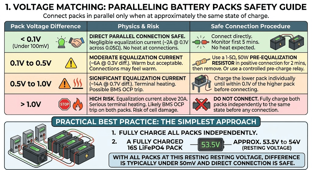
Every pack must be at approximately the same state of charge before being connected in parallel. The voltage difference between packs determines the magnitude of the equalisation current that flows when they are joined. The following table shows the safe ranges and the correct procedure for each.
| Pack Voltage Difference | Physics and Risk | Safe Connection Procedure |
| Under 0.1V (under 100mV) | Direct parallel connection safe. Equalisation current at 0.1V across 0.05 ohm combined pack impedance: approximately 2A. Negligible for lithium cells. | Connect directly. Monitor for first 5 minutes. No heat at connections expected. |
| 0.1V to 0.5V | Moderate equalisation current. At 0.3V difference and 0.05 ohm impedance: 6A. Warm but acceptable. Connections may feel slightly warm to touch. | Use a 1 to 5 ohm, 50W pre-equalisation resistor in the positive connection for the first 2 minutes, then remove. Or connect via a controlled pre-charge relay. |
| 0.5V to 1.0V | Significant equalisation current. At 0.7V difference: approximately 14A. Terminal heating. Possible BMS OCP trip. | Charge the lower pack individually until within 0.1V of the higher pack before connecting in parallel. |
| Above 1.0V | High risk. Equalisation current above 20A. Serious terminal heating. Likely BMS OCP trip on both packs. Risk of cell damage. | Do not connect. Fully charge both packs independently to the same state before making any parallel connection. |
In practice, the simplest approach is to fully charge all packs independently before connecting them in parallel. A fully charged 16S LiFePO4 pack sits at approximately 53.5 to 54V after the charge current has dropped to near zero and the voltage has relaxed from the 58.4V CV endpoint. With all packs at this resting voltage, the difference between them will typically be under 50mV and direct connection is safe.
2. Equal Cable Lengths
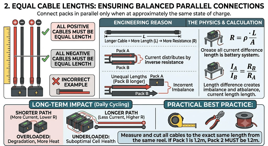
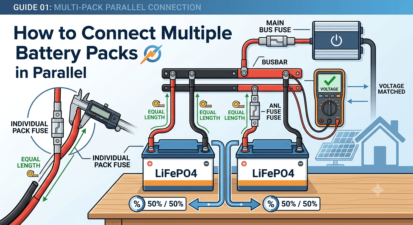
Measure and cut all positive cables to the same length and all negative cables to the same length before beginning any installation work. This is not an approximation. If Pack 1’s P+ cable is 1.2 metres, Pack 2’s P+ cable must also be 1.2 metres, cut from the same reel of the same cable type.
The engineering reason: cable resistance is proportional to length. A cable 50% longer has 50% more resistance. In a parallel system where current distributes by inverse resistance ratio, a 50% resistance difference between paths creates a 33% current imbalance. Over years of daily cycling, the pack on the lower-resistance path carries more current, generates more heat, and degrades faster. The pack on the higher-resistance path is underloaded and cycles at below its designed rate, which is also suboptimal for cell health.
The specific calculation showing how cable length difference translates to current imbalance, with worked examples, is in our article on busbar sizing, cable sizing, and fuse selection. The voltage drop formula V = I x (rho x L / A) tells you both the voltage drop and by rearrangement the current distribution between parallel paths.
3. Individual Pack Fuses
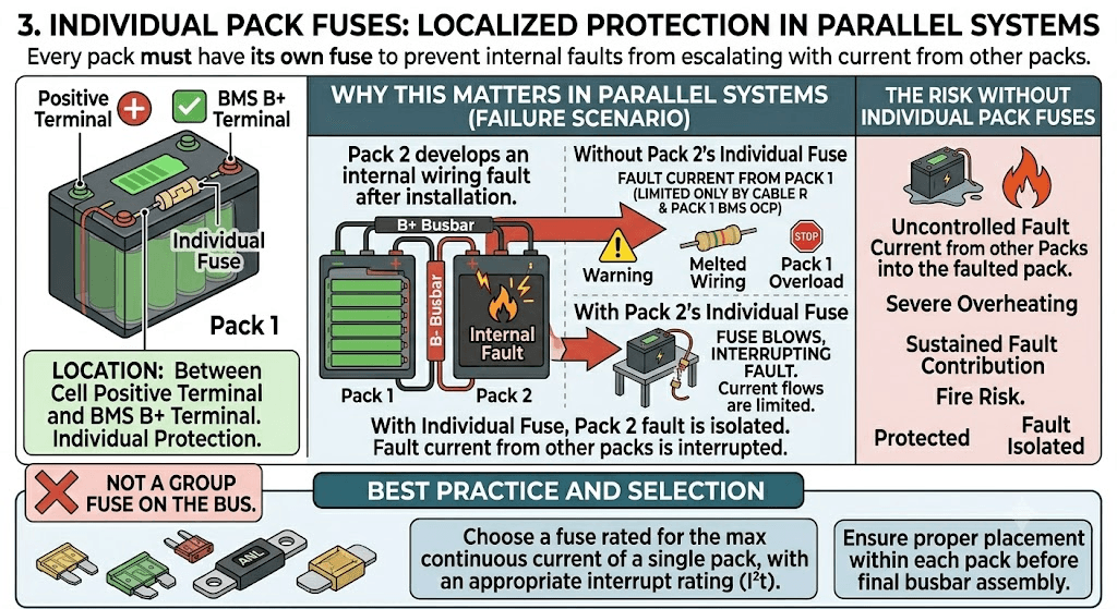
Every pack must have its own fuse between the positive cell terminal and the BMS B+ terminal before the parallel bus is assembled. This is not a group fuse on the bus. Each individual pack needs its own protection against a wiring fault within that pack’s internal circuit.
The reason this matters in a parallel system specifically: if Pack 2 develops an internal wiring fault after Pack 1 is already connected to the bus, Pack 1 can supply fault current through the bus into Pack 2’s fault. Without Pack 2’s individual fuse, this fault current is limited only by cable resistance and Pack 1’s BMS OCP threshold. With Pack 2’s individual fuse, the fuse interrupts the fault current and protects both the Pack 2 wiring and Pack 1 from sustained fault contribution.
Current Sharing:
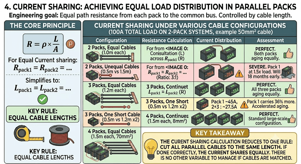
In a multi-pack parallel system, the engineering goal is equal current sharing between all packs. This is achieved by equal path resistance from each pack to the common bus. Cable resistance is the primary controllable variable. The calculation is straightforward.
For a single-way cable path of length L, cross-section A (in square metres), carrying current I:
R = rho x L / A (rho for copper = 1.72 x 10⁻⁸ ohm-metres)
For equal current sharing: R_pack1 = R_pack2 = … = R_packN
Since all packs use the same cable cross-section (same gauge), this reduces to: L_pack1 = L_pack2 = … = L_packN
Equal cable lengths. That is the entire calculation. The following table shows what current sharing looks like under various cable configurations for a 100A total inverter load on a two-pack system.
| Configuration | Resistance Calculation | Current Distribution | Assessment |
| 2 packs, equal cable (1.0m each, 50mm2) | Each pack: R = 1.72e-8 x 1.0 / 50e-6 = 0.000344 ohm | Pack 1: 50A, Pack 2: 50A | Perfect. Both packs aging equally. |
| 2 packs, unequal cable (0.5m vs 1.5m, 50mm2) | Pack 1: 0.000172 ohm. Pack 2: 0.000516 ohm. Ratio: 3:1 | Pack 1: ~75A, Pack 2: ~25A | Severe. Pack 1 at 1.5x rated load. Will fail 18 months early. |
| 3 packs, equal cable (1.2m each, 50mm2) | Each pack: R = 1.72e-8 x 1.2 / 50e-6 = 0.000413 ohm | Each pack: 33A | Perfect. All three packs aging equally. |
| 3 packs, one short cable (0.5m vs 1.2m x2) | Pack 1: 0.000172 ohm. Packs 2+3: 0.000413 ohm each | Pack 1: ~45A, Packs 2+3: ~27.5A each | Pack 1 carries 36% more than its share. Accelerated aging. |
| 4 packs, equal cable (1.5m each, 70mm2) | Each pack: R = 1.72e-8 x 1.5 / 70e-6 = 0.000369 ohm | Each pack: 25A at 100A load | Perfect. Standard large-scale configuration. |
| KEY TAKEAWAY | The current sharing calculation reduces to one rule: cut all parallel cables to the same length. If you have done that correctly, the current shares equally. There is no other variable to manage if the cables are matched. |
Fuse Architecture for Multi-Pack Systems
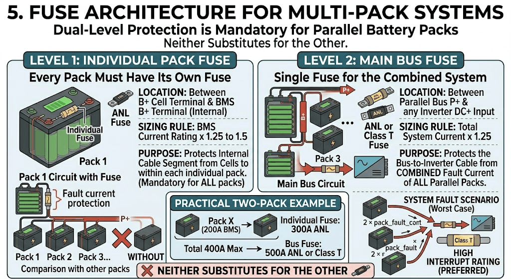
A multi-pack parallel system has two levels of fuse protection, and both are required. Neither substitutes for the other.
| Fuse Location | Sizing Rule | Purpose |
| Individual pack fuse | Each pack has its own fuse between B+ cell terminal and BMS B+ terminal. Sized at BMS current rating x 1.25 to 1.5. | Protects the cable segment from cells to BMS within each individual pack. Must be present on every pack regardless of bus fuse. |
| Main bus fuse | Single fuse between the parallel bus P+ and the inverter DC positive input. Sized at total system current x 1.25. | Protects the bus-to-inverter cable from combined fault current of all parallel packs. For 2 x 200A BMS packs: total 400A max, bus fuse 500A ANL or Class T. |
For a two-pack system with 200A BMS units each: individual pack fuses at 300A ANL each, bus fuse at 500A ANL or Class T. The bus fuse must be rated for the combined fault current of both packs, which in a worst case could approach 2 x pack_fault_current. Class T fuses with high interrupt ratings are preferred for the bus fuse at large parallel configurations.
The full fuse sizing methodology including ANL versus Class T selection is covered in busbar sizing, cable sizing, and fuse selection for LiFePO4 battery packs. The multi-pack bus fuse sizing follows the same principles as the single-pack fuse, scaled to the combined system current.
BMS Configuration for Multi-Pack Systems
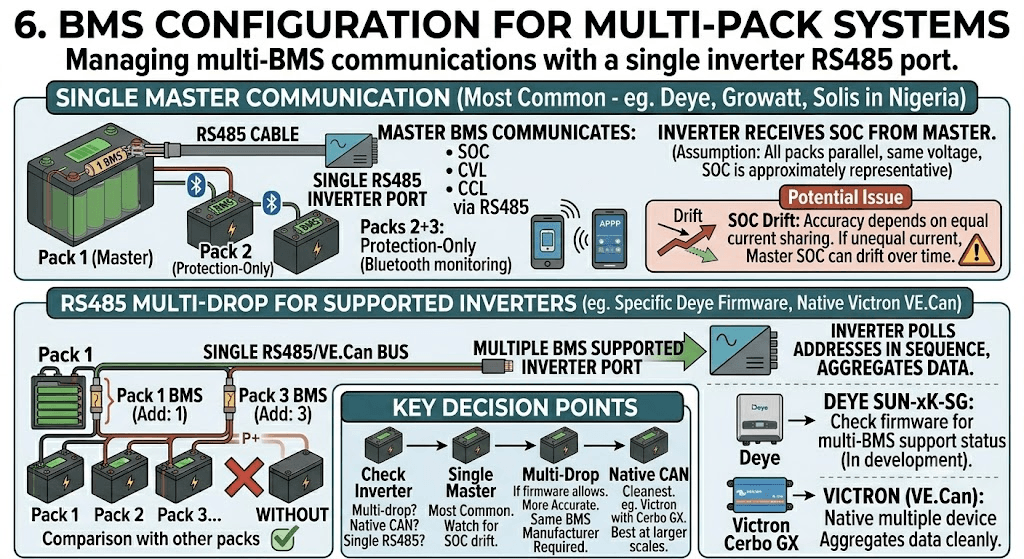
Each pack has its own BMS. Each BMS protects its own cells independently. The question is how they communicate with the inverter when there are multiple BMS units but only one RS485 port on the inverter.
Single Master Communication
The most common approach for Nigerian installations with Deye, Growatt, and Solis inverters is single-master communication. One BMS is designated the master and communicates SOC, CVL, CCL, and DCL to the inverter via RS485. The other BMS units operate as protection-only units for their individual packs, with their Bluetooth apps available for monitoring but no RS485 communication to the inverter.
The inverter receives SOC data from the master BMS. Because all packs are in parallel at the same voltage, the master BMS’s SOC reading is approximately representative of the entire bank’s state. The accuracy of this representation depends on how well current is sharing between packs. If current sharing is equal, the master BMS’s coulomb count is representative. If one pack is carrying significantly more current than another, the master BMS’s SOC drifts from the true bank state over time.
This SOC drift in multi-pack systems is covered in depth in Phase 4 Article 6 of this cluster. For the single-pack communication foundation, our article on smart BMS vs standard BMS explains why accurate SOC communication matters so much for inverter decision quality.
RS485 Multi-Drop for Supported Inverters
Some inverter firmware versions support multi-drop RS485 communication where multiple BMS units are connected on the same RS485 bus, each with a unique Modbus address. The inverter polls each address in sequence and aggregates the data. This is a more accurate approach for multi-pack monitoring but requires the inverter firmware to support it and all BMS units to be from the same manufacturer with compatible register maps.
For Deye SUN-xK-SG series: check the current Deye firmware release notes at deye.com.cn/global for multi-BMS support status. This feature has been in development and may be available in newer firmware versions for the SUN-5K and SUN-10K models.
For Victron systems: Victron’s VE.Can bus natively supports multiple devices including multiple BMS units. Each BMS connects to the VE.Can bus and the Cerbo GX aggregates data from all of them. This is the cleanest multi-pack communication architecture available and is one reason Victron installations tend to perform better at larger scales. Full documentation is available at victronenergy.com/live.
The Connection Sequence: Step by Step
Connection order matters. Connecting packs to a live bus without following a controlled sequence risks large equalisation current events and BMS OCP trips. Here is the correct sequence.
- Verify all packs are within 0.1V of each other at the terminal. If not, charge the lower packs individually first.
- Assemble the parallel bus (positive busbar and negative busbar) without connecting any pack yet. The bus is floating, not energised.
- Connect Pack 1 P- to the negative bus. Connect Pack 1 P+ to the positive bus via Pack 1’s pre-charge circuit. Allow 500ms then close the bypass relay. Pack 1 is now energised and the bus is at Pack 1’s voltage.
- Connect Pack 2 P- to the negative bus. Connect Pack 2 P+ to the positive bus through a 2 to 5 ohm equalisation resistor for 30 seconds. The resistor limits the equalisation current as Pack 2 adjusts to match the bus voltage. After 30 seconds, remove the resistor and make the direct connection.
- Repeat step 4 for each additional pack, one at a time.
- After all packs are connected to the bus, connect the bus to the inverter through the main bus fuse and the inverter pre-charge circuit.
- Power up the inverter. Open all BMS apps. Verify all packs show normal cell voltages and no active fault codes.
- Apply a load of at least 50% inverter rated output. Read all BMS app current readings simultaneously. Verify current distribution is within 15% between packs.
| WHY EACH PACK GETS A RESISTOR | The equalisation resistor at each new pack connection limits the current surge when the new pack first touches the bus. Even if voltages appear matched, connection resistance, inductive effects, and measurement error mean a small voltage difference always exists. The resistor converts this difference into a gradual current ramp rather than an instantaneous surge. It is the same principle as the pre-charge circuit for inverter capacitor inrush, applied to pack-to-bus connection. |
Four Checks That Cannot Be Skipped
Commissioning a multi-pack parallel system is not complete until these four verifications are done and recorded. They establish the baseline against which future performance checks are compared.
| Stage | Actions and Verification |
| Pre-connection | Measure terminal voltage of each pack. Confirm all within 0.1V of each other. If not, charge the lower packs first. Confirm equal cable lengths from each pack P+ to the bus and P- to the bus. Visual inspection of all connection points. |
| First connection | Connect Pack 1 to the bus first. It becomes the sole supply. Connect Pack 2 P- first, then P+ through a 2-ohm resistor for 30 seconds, then direct. Repeat for each additional pack in sequence. Monitor each BMS app during connection for abnormal current. |
| Communication setup | Configure Pack 1 BMS as master (RS485 address 1). Configure Pack 2 BMS as RS485 address 2, etc. Set inverter battery type to the correct BMS brand. Verify inverter display shows SOC as percentage from the master BMS. |
| Load test | Apply a representative load (at least 50% of inverter rated output). Open all BMS apps simultaneously. Verify current distribution is within 15% between packs. Record baseline current per pack for future comparison. |
| 30-day check | Re-read BMS app current readings under load. Compare against commissioning baseline. Any pack showing more than 20% divergence from its baseline share has a wiring or connection quality change that needs investigation. |
The full 10-stage system commissioning protocol that wraps these pack-level checks into the complete inverter and MPPT commissioning process is in our hybrid solar system commissioning checklist. Stage 5 covers BMS communication verification and Stage 7 covers load testing, both of which apply directly to multi-pack configurations.
Worked Example: Adding a Second Pack to an Existing 5kVA Deye System
A residential customer in Lagos has an existing 5kVA Deye SUN-5K-SG03LP1 with one 200Ah 48V LiFePO4 pack on a JK BMS 200A. They want to add a second identical 200Ah pack to double their overnight runtime. Here is the complete procedure.
Step 1: Specify the second pack identically
Second pack: 16 cells, 200Ah Grade A LiFePO4, JK BMS 200A RS485 active balancer. Configure the second BMS identically to the first: OVP 3.65V, UVP 2.80V, charge OTP 50 degC, balance threshold 10mV, balance current 2A.
Step 2: Cable the second pack with equal length cables
Measure the existing cable from Pack 1 P+ to the positive bus connection point. Cut the Pack 2 P+ cable to the same length. Repeat for P-. If the existing installation used 50mm2 cable, the new cable must also be 50mm2. Do not use 35mm2 for the new pack even if the run is short.
Step 3: Add individual fuse to new pack
Install a 300A ANL fuse between the Pack 2 B+ cell terminal and the Pack 2 BMS B+ terminal. Confirm Pack 1 already has its own individual 300A ANL fuse. If not, add one before proceeding.
Step 4: Add main bus fuse
With two 200A BMS packs, total maximum system current is 400A. Install a 500A Class T fuse on the main bus positive between the parallel bus and the inverter DC positive input. Remove any existing undersized bus fuse and replace with the correctly rated unit.
Step 5: Charge both packs to the same state
Charge Pack 2 independently to full. Allow it to rest for 30 minutes. Measure terminal voltage. Compare against Pack 1 terminal voltage. Both should be within 50mV. If Pack 1 has been in service and is at a lower SOC, charge Pack 1 to full as well before making the parallel connection.
Step 6: Connect in sequence
Disconnect Pack 1 from the inverter temporarily. Connect Pack 2 P- to the bus, then Pack 2 P+ through a 3-ohm resistor for 30 seconds, then direct. Reconnect Pack 1. Connect the combined bus to the inverter through the pre-charge circuit and the new 500A bus fuse.
Step 7: Configure RS485
Pack 1’s BMS remains the RS485 master (address 1). Pack 2’s BMS is set to RS485 address 2 in the JK BMS app. The Deye inverter communicates only with address 1 (unless Deye firmware supports multi-BMS polling for this model version). Verify the Deye display shows SOC as percentage. Cross-reference with Pack 1’s BMS app.
Step 8: Verify current sharing
Apply a 3 to 4 kW load (approximately 60 to 80A at 48V). Open both JK BMS Bluetooth apps simultaneously. Pack 1 should show approximately 30 to 40A and Pack 2 should show approximately 30 to 40A. If the split is within 15%, the installation is correctly balanced. If not, recheck cable lengths and connection quality. Our article on SOC drift: why your BMS and inverter disagree explains how to diagnose whether a current sharing imbalance is producing SOC error in the master BMS reading.
What Goes Wrong and How to Recognise It
| PROBLEM 1: One pack consistently reports higher current than the other | Root cause: cable length inequality. Fix: measure both cable paths with a milliohm meter or by physical measurement. Cut cables to equal length. Reconnect. Verify current sharing under load. |
| PROBLEM 2: One pack BMS trips OCP while the other remains connected | Root cause: the tripping pack is carrying too much current due to cable imbalance, or its OCP threshold is set too low relative to its actual share. Fix: verify current sharing first. If sharing is equal but OCP is still tripping, check whether the BMS OCP threshold matches the configured level and whether the BMS current sensor has drifted. Our article on signs of a failing BMS covers the current sensor drift diagnostic. |
| PROBLEM 3: Inverter SOC reading diverges from pack actual state over time | Root cause: the master BMS SOC is being calculated from only half (or one third) of the total system current. If current sharing is unequal and the master pack is carrying more current than reported, the SOC calculation will show the battery emptying faster than the combined bank actually is. Fix: correct the cable imbalance, verify equal current sharing, then recalibrate master BMS SOC to 100% after a full charge. |
| PROBLEM 4: Large voltage difference between packs after a period of operation | Root cause: the BMS units on each pack are set to different protection thresholds, or one BMS’s active balancer has failed and that pack’s cells are drifting. Fix: compare BMS configurations via Bluetooth app on both packs. Verify thresholds match. Check that both balancers are active during the CV phase. |
Multi-Pack Wiring for Pylontech Batteries
Pylontech batteries (US2000C, US3000C, UP5000) have their own specific parallel wiring requirements that differ from DIY LiFePO4 packs. Pylontech uses a master-slave communication architecture where one battery is the master and the rest are slaves. The master aggregates data from all slaves and presents a single communication interface to the inverter.
Key Pylontech parallel wiring rules: maximum 8 units per parallel bank for US2000C and US3000C. Connect power cables (large red and black) first, in the order shown in the Pylontech installation manual. Then connect communication cables in the daisy-chain order shown, from master to slave 1 to slave 2 and so on. The master is always the battery connected to the inverter RS485 port. Setting the master is done by physical jumper or DIP switch depending on the model.
The complete Pylontech parallel wiring procedure including the specific cable routing and DIP switch configuration is documented in our article: how to wire Pylontech batteries in parallel. Pylontech also maintains installation guides for each battery model at pylontech.us/resource-center, which should be consulted alongside our field guide for model-specific details.
The Five Rules of Multi-Pack Parallel Systems
If you take nothing else from this article, take these five rules. They are the difference between a parallel battery system that runs well for 10 years and one that starts showing problems in year 2.
- Equal cable lengths from every pack to the common bus. This is the most important physical requirement. Not approximately equal. Exactly equal.
- Voltage match all packs to within 0.1V before connecting them. Charge packs independently to full before making the parallel connection.
- One BMS per pack, one individual fuse per pack, one bus fuse for the combined system. Never skip any of these.
- Verify current sharing within 15% between all packs under representative load after commissioning. Record the baseline values. Check them again at 6 months.
- Configure one BMS as RS485 master for the inverter. Monitor the other packs via Bluetooth. Set identical protection thresholds on all BMS units.
Phase 4 of the Eneronix BMS cluster builds on these foundations with more advanced multi-pack topics including master-slave BMS architecture in Phase 4 Article 2, state-of-charge synchronisation across parallel packs in Phase 4 Article 6, and the engineering framework for battery bank expansion versus replacement decisions in Phase 4 Article 8. The complete battery bank sizing calculation that determines how many parallel packs your system actually needs is in our battery bank sizing guide for off-grid systems, and for commercial-scale installations our article on how to size an off-grid solar system for commercial buildings covers the load analysis and battery capacity calculation from first principles.
Frequently Asked Questions
How many battery packs can I connect in parallel?
Technically there is no hard upper limit set by battery chemistry. Practically, the number of parallel packs is limited by cable management complexity, BMS communication addressing capacity, inverter communication channel support, and the diminishing returns of very large battery banks relative to inverter output. For residential and small commercial Nigerian solar systems, 2 to 4 parallel packs is the typical range. Beyond 4 packs at 48V, the current management and monitoring complexity increases significantly and the system benefit per additional pack decreases. For Pylontech batteries specifically, the manufacturer supports up to 8 units in a single parallel bank as documented at pylontech.us.
Do all parallel packs need to be the same capacity?
For the best long-term performance, yes. Parallel packs of different capacities share current unequally even with equal cable lengths, because different-capacity packs typically have different internal resistance profiles. A 200Ah pack and a 100Ah pack in parallel will not deliver equal current sharing. The 200Ah pack carries more current over time, ages faster, and the pack diverges. For a permanent multi-pack installation designed to last years, use identical packs with matched cells. If a pack must be replaced and the replacement has slightly different capacity from the original, test internal resistance and confirm current sharing within 15% under load before accepting the configuration.
What is the correct order to connect parallel battery packs?
Connect all packs to a de-energised bus sequentially. Connect Pack 1 first. Then connect each subsequent pack one at a time through a pre-equalisation resistor if the voltages differ by more than 0.1V. Always connect the negative terminal of each new pack before the positive. After all packs are connected to the bus, verify BMS app readings are normal on all packs before connecting the bus to the inverter through the pre-charge circuit.
Why is equal cable length so important for parallel packs?
Current distributes between parallel packs in inverse proportion to the resistance of each current path. Cable resistance is the primary variable in a well-designed system. A pack connected via a 0.5m cable has half the path resistance of one connected via a 1.0m cable and therefore carries twice the current. Over 18 months of daily cycling at double the designed current share, that pack degrades significantly faster than its counterpart. Equal cable lengths create equal path resistance and therefore equal current sharing. This is documented in IEC 62619 as a safety requirement for parallel lithium battery configurations.
Can I mix different brands of battery packs in parallel?
Not recommended. Different brands have different cell chemistry details, different BMS protection thresholds, different internal resistance profiles, and different aging characteristics. Mixing brands creates immediate and growing imbalance between strings. The BMS units from different brands also communicate differently to the inverter, making aggregate SOC reporting unreliable. For the best results, use identical packs from the same manufacturer and ideally the same production batch. If the system is expanding over time and the original brand is no longer available, choose a replacement with as similar a specification as possible and verify current sharing carefully after installation.
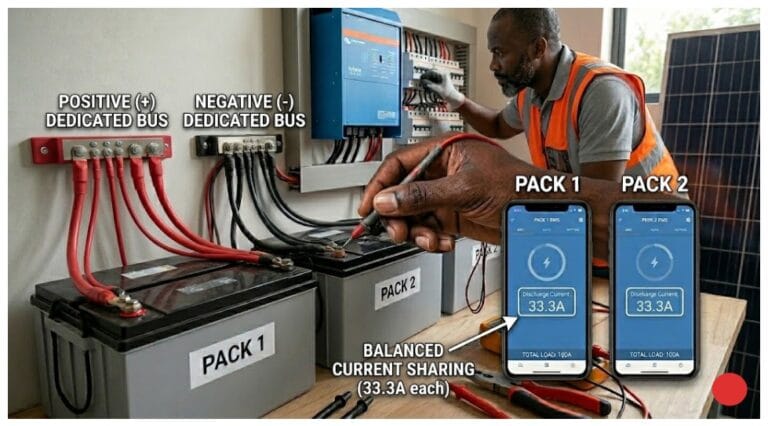
How do I know if my parallel packs are sharing current equally?
Open all BMS apps simultaneously while the system is under a load representative of normal evening demand. Read the discharge current reported by each BMS. In a correctly wired two-pack system with equal cable lengths, both should report approximately 50A each at 100A total load, within 10 to 15% tolerance. In a three-pack system, approximately 33A each. If one pack is consistently showing significantly higher or lower current than the others, investigate cable length and connection resistance at that pack’s bus connection point.

I am Engr. Ubokobong Ekpenyong, a solar specialist and lithium battery systems engineer with over five years of hands-on experience designing, assembling, and commissioning off-grid solar and energy storage systems. My work focuses on lithium battery pack architecture, BMS configuration, and system reliability in off-grid and high-demand environments.