Maximum Charging Current for a 100Ah Lithium Battery (Engineering Guide)
What is the maximum charging current for a 100Ah lithium battery? Learn the correct amps (20A–100A), BMS limits, and safe charging range for long lifespan.
If you want the direct engineering answer without the full breakdown, the table below summarises the correct charging current limits for a 100Ah LiFePO4 battery.
Maximum Charging Current for a 100Ah Lithium Battery
Parameter
Value (100Ah LiFePO4 Battery)
Explanation
Cell Chemistry Limit (Absolute Max)
100A (1C)
Maximum current the cells can physically accept under ideal conditions. Not recommended for regular use due to heat and accelerated degradation.
BMS Charge Current Limit (CCL)
30A – 50A (Typical)
Hard limit enforced by the Battery Management System. Exceeding this triggers protection shutdown.
Recommended Daily Charging Current
20A – 30A (0.2C – 0.3C)
Best range for long battery lifespan, especially in hot climates like Nigeria.
Maximum Recommended Charging Current
50A (0.5C)
Upper safe operating limit for faster charging, but not ideal for daily use.
Ideal Solar Charging Target
20A – 30A
Optimized for longevity and thermal stability in off-grid systems.
When an installer, system integrator, or technically aware system owner asks what is the maximum charging current is for a 100Ah lithium battery, they typically receive one number in response, usually 50A. That answer is not wrong, but it is incomplete in ways that matter operationally. There are actually three distinct current thresholds that govern charging a 100Ah LiFePO4 battery, and conflating them is one of the more consistent sources of both system misconfiguration and premature battery failure in the field.
The first threshold is the cell chemistry limit. Standard LiFePO4 cells are rated for 1C continuous charge current. For a 100Ah battery, that is 100A. At this rate the cells will accept charge without immediate damage as long as the BMS does not intervene. However, operating at 1C generates significant internal heat, and in a tropical installation environment already running above 35°C ambient, the cumulative thermal stress at 1C charge rates accelerates capacity fade well beyond what the rated cycle life specification assumes.
The second threshold is the BMS-enforced Charge Current Limit, or CCL. This is the hard operating ceiling transmitted by the Battery Management System to the charge sources. On most 100Ah LiFePO4 batteries available in the Nigerian market, the BMS CCL is set at 50A. On premium-specified packs with higher-rated BMS hardware, the CCL may be 100A. On some budget units, it is 30A or lower. The BMS CCL is what the system must actually respect in operation. Exceeding it triggers an overcurrent protection trip, disconnecting the battery from the charge source until the fault condition clears.
The third threshold is the recommended daily operating current for longevity. This sits between 0.2C and 0.5C, which for a 100Ah battery is 20A to 50A. In tropical high-ambient-temperature environments, the conservative end of that range, 0.2C to 0.3C, meaning 20A to 30A, is what field experience and engineering best practice recommend for daily solar charging. This is not a safety limit. It is a longevity limit. The battery will not fail immediately at 50A in a hot room. It will age faster, and the degradation will be visible in capacity measurements within 12 to 18 months.
Understanding which of these three numbers applies to which aspect of system design is the foundation for configuring a charging system correctly. The cell limit tells you what the chemistry can handle under ideal conditions. The BMS CCL tells you what the system will allow before it protects itself. The recommended operating current tells you what to actually set in your MPPT controller and inverter charger for a system that delivers its rated service life.
This post works through all three in the context of real solar system design, with the calculation framework, configuration implications, and the specific failure modes that result when any of these limits is misapplied or ignored.
The C-Rate Formula and How Charging Current Is Calculated
C-rate is the standardised engineering unit for expressing charge and discharge current relative to a battery’s capacity. It eliminates the ambiguity of specifying amps in isolation, which carries no meaning without a capacity reference. A charging current of 50A means something very different applied to a 50Ah battery versus a 500Ah bank. C-rate normalises the comparison.
The governing equation is straightforward.
C-rate = Charge Current (A) / Battery Capacity (Ah)
Rearranged to derive the current from a known C-rate target:
Charge Current (A) = C-rate x Battery Capacity (Ah)
Applied to a 100Ah LiFePO4 battery, the three reference points work out as follows.
At 1C, the charge current is 100A. At this rate a fully depleted 100Ah battery would reach full charge in approximately one hour under constant current conditions, though the actual time is longer because the constant voltage phase at the top of charge tapers the current before the battery is genuinely full.
At 0.5C, the charge current is 50A. Charge time from empty to full is approximately two hours under similar conditions. This is the maximum recommended charge current cited in most LiFePO4 manufacturer datasheets and the figure most commonly quoted as the answer to the question this post addresses.
At 0.2C, the charge current is 20A. Charge time from empty extends to approximately five hours. This is the recommended daily operating rate in applications where ambient temperature is elevated and longevity is the primary optimisation target, which describes the majority of off-grid solar installations in Nigeria.
These are idealised figures. In practice, solar charge current is not constant. It rises with irradiance through the morning, peaks at midday, and falls through the afternoon. The MPPT controller tracks the array’s maximum power point and delivers whatever current the array can produce at that moment, limited by the controller’s programmed output current ceiling. If that ceiling is not explicitly set to respect the battery’s maximum charge current, the controller will attempt to deliver whatever the array produces, which on a clear harmattan afternoon with a large array can significantly exceed the battery’s safe operating range.
The C-rate calculation is also the correct starting point for array sizing. If the maximum recommended charge current for a 100Ah battery is 50A, and the system nominal charge voltage is 57.6V on a 48V LiFePO4 bank, the maximum array power that should be delivering charge to that battery is approximately 2,880W. An array significantly larger than this, paired with a controller whose output current limit has not been set correctly, will regularly push the battery above its CCL during peak solar hours, relying on the BMS overcurrent protection to clip the excess. This is not an acceptable operating condition and the implications are covered in detail in Section 3.
One nuance worth stating explicitly. The C-rate calculation uses the battery’s total nameplate capacity in Ah, not the usable capacity after applying a depth of discharge limit. If you are operating a 100Ah battery within a 20 to 90% SOC window, the available capacity for that cycle is 70Ah, but the C-rate calculation for maximum charge current still uses 100Ah as the denominator. The charge current limit applies to the cells regardless of where in the SOC range you are charging.
The BMS
The cell chemistry of a LiFePO4 battery may tolerate 1C charge current under controlled conditions. In a real installation, the BMS is what actually determines whether that current reaches the cells or triggers a protection disconnect. Understanding the distinction between what the chemistry can handle and what the BMS will allow is critical for any system designer or installer working with lithium battery packs.
The BMS monitors cell voltages, pack temperature, and current flow simultaneously during every charge and discharge event. When incoming charge current exceeds the BMS Charge Current Limit, the protection circuit opens the charge contactor and disconnects the battery from the charge source. The disconnect is instantaneous. From the inverter or MPPT controller’s perspective, the battery has suddenly disappeared from the DC bus. Depending on the inverter topology, this can cause a voltage spike on the DC rail, trigger an inverter fault, or in poorly designed systems, produce a transient that stresses other components.
The CCL on a given battery pack is set during BMS configuration at the factory and reflects a combination of the cell manufacturer’s specification, the BMS hardware’s continuous current rating, and the thermal management capability of the pack enclosure. On quality 100Ah LiFePO4 packs from established manufacturers, the CCL is typically set at 50A, which is 0.5C. On budget units with lower-rated BMS hardware, it may be 30A or less. On premium packs with high-specification BMS hardware, it can reach 100A.
The critical operational distinction is between a BMS CCL that is functioning as a hard safety backstop and one that is functioning as a routine operating limiter. These are two fundamentally different conditions with different consequences.
A BMS CCL functioning as intended is a protection layer that activates rarely, under fault conditions or during unusual events such as a generator delivering higher-than-expected current during a bulk charge (CV). The charge sources are configured to operate below the CCL, and the BMS only intervenes when something unexpected occurs.
A BMS CCL functioning as a routine operating limiter means the charge sources are regularly pushing current above what they should, and the BMS is tripping daily to clip the excess. This is a misconfigured system. The BMS contactor cycling under repeated overcurrent events generates mechanical wear on the protection circuit. More importantly, the brief period of overcurrent before the BMS trips, even if only milliseconds, generates a current and thermal spike in the cells that accumulates as degradation over hundreds of cycles.
Relying on the BMS to manage daily current limits by tripping repeatedly is equivalent to relying on a circuit breaker to function as a load switch. It works in the short term and destroys the protection device in the long term.
The correct configuration hierarchy places the charge current limit in the MPPT controller and inverter charger settings, not the BMS. The BMS CCL should sit above the charge sources’ programmed output current limit, with margin between them so that normal operation never approaches the BMS threshold. A well-designed system has the MPPT controller configured to a maximum output current of 0.5C or below, the inverter AC charger set to a maximum charge current within the same range, and the BMS CCL above both of those values acting as an emergency backstop.
In systems with active BMS-to-inverter communication via CAN bus, the BMS transmits its CCL dynamically to the charge sources in real time. The inverter and MPPT controller adjust their output current accordingly without requiring manual configuration. This architecture means the BMS can also reduce the CCL as temperature rises toward its thermal limits, allowing the charge sources to automatically back off charge rate during hot afternoon conditions without requiring any operator intervention. This is the correct implementation for installations in tropical environments where ambient temperature significantly affects safe operating current.
For a 100Ah battery without active BMS communication, the installer must programme the charge current limit manually in every charge source connected to the battery. The BMS’s published CCL is the ceiling. The recommended 0.2C to 0.5C operating range is the target. The gap between those two numbers is the safety margin the system should always maintain.
The Recommended Range for Daily Solar Operation
The distinction between the maximum permissible charge current and the recommended daily operating current is where most system configurations diverge from engineering best practice. Maximum permissible means the system will not immediately fail. Recommended operating means the system will deliver its rated service life under real-world conditions. In a tropical off-grid installation, those two figures are not interchangeable.
The recommended daily charge current range for LiFePO4 batteries in solar applications is 0.2C to 0.5C. For a 100Ah battery that is 20A to 50A. Within that range, the conservative end, 0.2C to 0.3C, meaning 20A to 30A, is the preferred target for installations where ambient temperature is consistently above 30°C and the battery room has limited ventilation. The reasoning is rooted in thermodynamics and the SEI layer growth mechanism.
Every charge cycle generates internal heat proportional to the square of the current and the cell’s internal resistance. At 0.2C, internal heat generation in a 100Ah LiFePO4 cell is modest and the cell temperature rise above ambient is typically 2 to 4°C. At 0.5C, the same cell generates approximately 6.25 times more resistive heat than at 0.2C, producing a temperature rise of 8 to 12°C above ambient under typical conditions. At 1C, the temperature rise can reach 20°C or more above ambient depending on the pack’s thermal management.
In a battery room running at 38°C ambient during the Nigerian dry season, a 100Ah battery being charged at 0.5C reaches 46 to 50°C at the cell level during bulk charge. This is at the threshold of the BMS high-temperature charge cutoff on most LiFePO4 packs, and well into the zone where SEI layer growth accelerates significantly. The same battery charged at 0.2C in the same room reaches 40 to 42°C at the cell level. That 6 to 8°C difference, sustained across every charge cycle over years of daily operation, produces a measurable difference in the battery’s remaining capacity by year three or four.
This is not theoretical. It is the pattern seen repeatedly in field diagnostics of solar installations where battery capacity fade has outpaced the manufacturer’s specified degradation curve. Almost invariably, the root causes include elevated installation temperatures and charge currents at or near the 0.5C limit rather than in the 0.2C to 0.3C operating range.
The practical concern from system designers and installers is usually charge time. If 0.2C is the preferred daily charge rate and the system needs to recharge from a significant discharge overnight, is there enough solar window to complete the charge at 20A?
The calculation is straightforward. A 100Ah battery discharged to 20% SOC needs to recover 70Ah of charge to reach 90% SOC. At 20A (0.2C), the constant current phase delivers approximately 70Ah in 3.5 hours. The constant voltage absorption phase adds another 30 to 60 minutes. Total charge time from 20% to 90% at 0.2C is approximately 4 to 5 hours. In Nigeria’s coastal and southern regions, peak solar irradiance typically runs from approximately 8:30 AM to 3:30 PM, providing 6 to 7 hours of productive charging. A 0.2C charge rate comfortably completes the daily recharge cycle within the available solar window in most cases.
Where the 0.2C target becomes challenging is in systems with undersized solar arrays relative to battery capacity, or during extended overcast periods when reduced irradiance limits charge current below even the 0.2C target. In these cases the battery may not reach full charge before sunset, and the system will enter the next night cycle with a partial state of charge. This is a system sizing problem, not a reason to increase the daily charge current limit. The correct response is array expansion or battery bank sizing recalculation, not accepting a higher daily thermal load on the cells as a workaround.
For systems using a generator as a backup charge source, the generator-side charge current requires explicit configuration in the inverter’s AC charger settings. Generators can deliver significantly higher charge current than the solar array, and an unconfigured inverter charger will attempt to charge at its maximum rated output, which on a 3kVA or 5kVA inverter typically exceeds 50A. The inverter AC charger maximum current must be set independently and should not exceed 0.5C of the battery bank capacity under any circumstances, with 0.3C preferred in high ambient temperature installations.
How Series and Parallel Configurations Change the Calculation
One of the most consistent sources of charging current misconfiguration in multi-battery installations is the failure to correctly account for how series and parallel connections affect the bank-level charge current limit. The calculation is not complicated, but the errors that result from getting it wrong range from nuisance BMS trips to sustained overcurrent events that compress the service life of every cell in the bank.
The fundamental rule is this. Series connections increase voltage without increasing capacity. Parallel connections increase capacity without increasing voltage. Charge current limits scale with capacity, not voltage. Understanding which configuration you are working with determines which current limit applies at the bank level.
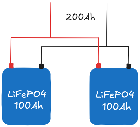
Parallel Configuration
Two 100Ah LiFePO4 batteries connected in parallel produce a bank with 200Ah total capacity at the same nominal voltage. Each battery’s BMS sees and manages only its share of the total charge current. If the system delivers 100A to the parallel bank, each battery receives approximately 50A, assuming equal internal resistance and matching battery state of charge. The bank-level maximum charge current scales proportionally with the number of parallel units.
For a 200Ah parallel bank with a per-battery CCL of 50A, the bank-level CCL is 100A. The MPPT controller and inverter charger should be configured to a maximum output current of 100A or 0.5C of 200Ah. At 0.2C the recommended daily operating current for this bank is 40A, which delivers a useful solar charge rate while keeping cell-level thermal load well within acceptable limits.
The caveat with parallel configurations is current sharing. Identical batteries from the same production batch with closely matched internal resistance will share current approximately equally. Batteries with differing ages, capacities, or internal resistance values will share unequally, with the lower-resistance unit carrying a disproportionately higher share of the charge current. In a parallel bank of significantly mismatched batteries, one unit may be operating at or above its individual CCL while the bank-level current appears within limit. This is why mixing old and new batteries in a parallel bank, or mixing batteries from different manufacturers, is a practice that should be avoided in any professionally designed system.
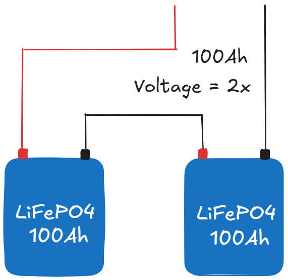
Series Configuration
Two 100Ah LiFePO4 batteries connected in series produce a bank with 100Ah capacity at double the nominal voltage. The critical point is that the same current flows through both series-connected batteries simultaneously. There is no splitting of current between units as there is in a parallel configuration. If the system delivers 50A to the series bank, each battery’s BMS sees the full 50A flowing through it.
The bank-level maximum charge current for a series configuration remains bounded by the most restrictive individual battery CCL in the string. If both batteries have a CCL of 50A, the bank maximum is 50A regardless of the elevated voltage. If one battery has a CCL of 50A and the other has a CCL of 30A due to a lower-specification BMS, the bank maximum is 30A. The weakest BMS in the series string sets the ceiling for the entire string.
This has direct implications for series-parallel banks, which are common in 48V systems built from 12V or 24V battery modules. A 48V bank assembled from four 12V 100Ah batteries in a 4S configuration has a bank capacity of 100Ah at 48V. The maximum charge current is the minimum CCL across all four series units, typically 50A on well-specified 12V packs. Increasing the number of series batteries does not increase the charge current ceiling. It only raises the operating voltage.
To increase both voltage and capacity, a 2S2P or 4S2P configuration is used, placing two or more parallel strings in series. A 48V bank assembled from eight 12V 100Ah batteries in a 4S2P configuration has a bank capacity of 200Ah at 48V. The charge current limit is now 2 x 50A = 100A, because the current splits between the two parallel strings, each of which sees 50A at the 100A bank input.
The Most Common Installation Error
The error seen most frequently in field diagnosis is a system where the installer has correctly calculated the bank voltage but has not adjusted the charge current limit to reflect the actual bank configuration. A 4S2P bank of 100Ah batteries is configured with a charge current limit of 50A rather than the correct 100A, resulting in a system that charges unnecessarily slowly and never reaches a proper full charge within the available solar window. Less commonly but more seriously, the charge current limit is left at a value calculated for a higher-capacity bank and the individual BMS units are subjected to sustained overcurrent, tripping repeatedly throughout the day.
Both errors are preventable with a two-minute configuration check at commissioning. Confirm the bank configuration, calculate the bank capacity, apply the 0.5C ceiling and 0.2C operating target to the bank capacity rather than the individual unit capacity, and verify that the MPPT controller and inverter charger output current limits reflect those values before energising the system.
Sizing the MPPT Controller and Solar Array to the Battery’s Charge Current Limit
The charge current limit of the battery bank is not just a parameter to configure in the MPPT controller. It is a fundamental input to the controller selection and array sizing calculations that should be resolved at the design stage, before any equipment is purchased. A system where the array capacity significantly exceeds what the battery can safely absorb is not a well-designed system with a conservative battery. It is a system with a structural mismatch that will stress the battery every clear day for the life of the installation.
The governing relationship is straightforward.
Maximum Array Power = Maximum Charge Current (A) x Battery Charge Voltage (V)
For a 100Ah LiFePO4 battery on a 48V system with a maximum charge current of 50A and a charge voltage of 57.6V, the maximum array power that should be delivering charge to that battery is approximately:
50A x 57.6V = 2,880W
At 0.2C operating target with a 20A preferred daily charge current, the array power delivering charge at that rate is:
20A x 57.6V = 1,152W
This does not mean the array must be limited to 1,152W. It means the MPPT controller’s output current limit should be configured to 20A for daily longevity operation, with the understanding that the controller will curtail array output above that level. In practice, array sizing slightly above the charge current target is standard to account for shading losses, soiling, temperature derating of panels, and suboptimal sun angles during morning and afternoon hours. An array delivering a peak of 1,400W to 1,600W, with the controller output limited to 20A to 25A, provides adequate charge capacity while maintaining the preferred thermal load on the cells.
The controller output current limit is the critical setting. It is distinct from the controller’s rated output current capacity, which is a hardware specification. A Victron SmartSolar MPPT 150/60 has a rated output current of 60A. That does not mean it will deliver 60A to every battery it is connected to. The output current limit in the controller configuration, set by the installer at commissioning, determines the actual maximum current the controller will deliver.
An installer who connects this controller to a 100Ah LiFePO4 battery and leaves the output current limit at the factory default is not configuring for longevity. The controller will deliver whatever the array can produce up to 60A, which on a large array will regularly exceed both the 0.5C ceiling and the BMS CCL.
The array sizing calculation above uses charge voltage rather than nominal battery voltage deliberately. During bulk charge the battery voltage is rising toward the absorption target, and the actual operating voltage is between nominal and absorption. Using the absorption voltage of 57.6V in the calculation produces a slightly conservative array limit, which is appropriate. Using nominal voltage of 51.2V would overstate the charge power available and understate the current delivered at a given power level.
For a parallel bank of two 100Ah batteries producing a 200Ah bank, the same calculation applies to the bank-level parameters. Maximum charge current is 100A at 0.5C of 200Ah. At 57.6V charge voltage, the maximum array power delivering charge at the 0.5C ceiling is approximately 5,760W. At 0.2C operating target the preferred daily charge power is approximately 2,304W. A 2,400W to 2,800W array with the controller output current limit set to 40A to 45A represents a well-matched system for this bank in a Nigerian tropical installation.
These calculations are exactly what the MPPT Solar and Charge Controller Calculator and the LiFePO4 Battery Bank Calculator on the Eneronix resources page execute with your actual system parameters. The MPPT calculator sizes the controller against the absorption voltage rather than nominal voltage, which is the correct methodology and one that most simplified sizing guides do not implement. The battery bank calculator produces the usable capacity, runtime scenarios, and charge time estimates at different C-rates so the array and controller sizing decisions can be made with full visibility of the system’s operating envelope. Both tools are free to use at the Eneronix Resources page.
One additional point on controller selection. The MPPT controller must be rated for an output current at least equal to the bank’s 0.5C ceiling, with margin. Selecting a controller rated exactly at the bank’s maximum charge current leaves no headroom and means the controller is operating at its rated limit during peak solar hours. A controller rated at 1.2 to 1.5 times the bank’s 0.5C ceiling operates in a more comfortable thermal range and provides headroom for future bank expansion without controller replacement.
Temperature Derating and Real Operating Limits
The maximum charge current figures published in battery datasheets are specified at 25°C. This is standard practice across the battery industry and it is a condition that most tropical off-grid installations never actually achieve in the battery room during charging hours. Understanding how ambient temperature modifies the effective operating current limit is essential for any engineer or installer specifying and commissioning systems in the Nigerian climate.
The mechanism is direct. As cell temperature rises, the internal resistance of the LiFePO4 cells increases, and the electrochemical processes that govern lithium ion intercalation into the anode structure become less efficient at high temperatures. The BMS monitors cell temperature continuously and applies a temperature-dependent reduction to the CCL once cell temperature exceeds a defined threshold. The specific threshold and reduction curve vary between manufacturers, but a representative profile looks approximately as follows.
Below 35°C, the BMS operates at full rated CCL. No derating applied. Between 35°C and 45°C, the BMS progressively reduces the CCL, typically cutting it to 60 to 80 percent of the rated value as temperature approaches 45°C. Above 45°C, most LiFePO4 BMS units enforce a charge cutoff entirely, transmitting CCL equal to zero to connected charge sources and opening the charge contactor until cell temperature drops below the reconnect threshold.
In a Nigerian installation with a poorly ventilated equipment room, the sequence from full CCL to charge cutoff can complete within a few hours on a hot dry-season afternoon. The solar array is at peak production. The battery is accepting charge at close to its rated current. The room temperature climbs through 38°C by midday.
Cell temperature, already elevated by internal resistive heating during bulk charge, reaches 45 to 48°C by early afternoon. The BMS reduces and then cuts the CCL. The MPPT controller, if it is communicating with the BMS via CAN bus, backs off charge current accordingly. If it is not communicating and relies on fixed voltage setpoints, it continues pushing charge voltage while the BMS protection circuit opens and closes repeatedly in an attempt to manage the thermal excursion.
This repeated contactor cycling is one of the more damaging operational patterns a lithium battery can experience. Each open-close event of the BMS contactor under load produces an arc across the contacts. The arc erodes the contact surface incrementally. Over hundreds of cycling events the contactor develops elevated contact resistance, which generates additional heat at the protection point, which accelerates further degradation of the protection circuit. The root cause in almost every case is an installation where the ambient temperature management was not addressed at commissioning and the charge current was set at or near the 0.5C ceiling rather than the conservative 0.2C to 0.3C target appropriate for the thermal environment.
The practical engineering response has two components. The first is installation environment. The battery room must maintain ambient temperature below 35°C during charging hours. A thermostatically controlled exhaust fan with inlet ventilation, sized to exchange the room air volume at least four to six times per hour, is the minimum effective intervention for most residential and small commercial installations. West-facing walls, roof space mounting, and fully sealed enclosures are disqualifying installation conditions for any LiFePO4 battery intended to achieve its rated service life.
The second component is charge current setting. In any installation where the ambient temperature during charging hours is consistently between 30°C and 38°C, the daily charge current target should be set at 0.2C rather than 0.5C. The additional time required to complete the daily charge cycle at 0.2C is acceptable in all but the most undersized solar installations.
The reduction in cell-level heat generation at 0.2C versus 0.5C in a 35°C ambient room is the difference between cell temperatures of 39 to 41°C and 43 to 47°C during bulk charge. That 4 to 6°C reduction is not marginal in the context of the SEI growth rate curves documented in the battery degradation literature. It represents a meaningful extension of the battery’s operating life at the temperatures typical of Nigerian field installations.
For systems with active BMS-to-inverter communication, the temperature derating is handled automatically by the BMS transmitting a reduced CCL to the charge sources as temperature rises. This is the correct architecture for tropical installations and one of the strongest arguments for specifying batteries with established communication protocols such as Pylontech CAN or BYD CAN rather than batteries that communicate only via a dry-contact relay. The relay-only system has no mechanism to reduce charge current as temperature climbs short of a full protection disconnect. The communicating system modulates charge current continuously, keeping the cells within their optimal operating window without requiring BMS intervention.
What is the maximum charging current for a 100Ah lithium battery?
The maximum charging current depends on three limits:
100A (1C) – absolute chemical limit
~50A – typical BMS limit
20A–30A – recommended daily operating range
For real-world systems, 20A–50A is the correct usable range, depending on performance vs lifespan priority.
Can I charge a 100Ah LiFePO4 battery at 100A?
Technically yes (1C), but it is not recommended in real installations. Charging at 100A:
Generates excessive heat
Accelerates degradation
May trigger BMS protection
Use only in controlled or manufacturer-approved conditions.
What is the best charging current for battery longevity?
0.2C to 0.3C (20A–30A for 100Ah) is optimal.
This:
Minimizes heat generation
Reduces internal resistance stress
Extends cycle life significantly
This is especially critical in high-temperature environments.
Is 50A safe for a 100Ah lithium battery?
Yes, 50A (0.5C) is generally safe and widely used.
However:
It is the upper recommended limit
Daily use at this level can shorten lifespan over time
Better to use 20A–30A for routine charging
What happens if charging current exceeds the BMS limit?
The Battery Management System will:
Disconnect the battery instantly
Trigger overcurrent protection
Cause system instability (inverter faults, voltage spikes)
Repeated events can:
Damage the BMS contactor
Reduce system reliability
How does temperature affect charging current?
Temperature has a major impact:
Above 35°C, safe charging current reduces
At 45°C, many BMS units cut off charging completely
In hot climates:
Use lower charge currents (0.2C)
Ensure proper ventilation
How do I set charging current on my solar system?
You must configure:
MPPT controller output current limit
Inverter charger current setting
Set both to:
20A–30A (longevity focus)
Or max 50A (performance focus)
Never rely on the BMS to control daily charging
Does battery configuration affect charging current?
Yes:
Parallel batteries → increase current capacity
2 × 100Ah = 200Ah → max ~100A
Series batteries → current stays the same
2 in series = still 100Ah → max ~50A
Always calculate based on total Ah capacity, not voltage.
What size solar array is suitable for a 100Ah battery?
At 48V system:
50A limit → ~2,880W array
20A target → ~1,150W array
Always ensure:
MPPT current limit is configured properly
Array does not overpower battery charging limits
Can I charge faster using a generator?
Yes, but:
Inverter charger must be manually limited
Never exceed 0.5C (50A)
Prefer 0.3C (~30A) for longevity
Unrestricted generator charging is a common cause of battery damage.
Conclusion
The maximum charging current for a 100Ah lithium battery is not a single figure. It is a three-tier specification that must be correctly interpreted and applied at each layer of the system design.
The cell chemistry limit of 1C, meaning 100A for a 100Ah battery, defines what the electrochemistry can tolerate under ideal laboratory conditions at 25°C. It is not a field operating target. The BMS CCL, typically 50A on most 100Ah LiFePO4 packs, defines the hard ceiling that the charge sources must be configured to respect, with margin, so the BMS functions as a safety backstop rather than a daily current limiter.
The recommended daily operating current of 0.2C to 0.3C, meaning 20A to 30A for a 100Ah battery in a tropical environment, is the figure that should appear in the MPPT controller and inverter charger output current limit settings in any installation where ambient temperature consistently exceeds 30°C during charging hours.
Series and parallel bank configurations scale these limits proportionally to bank capacity, not voltage. MPPT controller sizing must reference the battery charge voltage rather than nominal voltage in the array power calculation to avoid systematic undercalculation of the current at peak irradiance. And temperature derating reduces the effective operating ceiling further as ambient and cell temperatures rise, making active BMS-to-inverter communication the preferred architecture for any installation where thermal management cannot guarantee stable sub-35°C cell temperatures during bulk charge.
Getting these parameters right at the design stage costs nothing beyond the engineering time required to calculate them. Getting them wrong costs a battery replacement within three to five years in a system designed to last ten.
I am Engr. Ubokobong Ekpenyong, a solar specialist and lithium battery systems engineer with over five years of hands-on experience designing, assembling, and commissioning off-grid solar and energy storage systems. My work focuses on lithium battery pack architecture, BMS configuration, and system reliability in off-grid and high-demand environments.
Contains information related to marketing campaigns of the user. These are shared with Google AdWords / Google Ads when the Google Ads and Google Analytics accounts are linked together.
90 days
__utma
ID used to identify users and sessions
2 years after last activity
__utmt
Used to monitor number of Google Analytics server requests
10 minutes
__utmb
Used to distinguish new sessions and visits. This cookie is set when the GA.js javascript library is loaded and there is no existing __utmb cookie. The cookie is updated every time data is sent to the Google Analytics server.
30 minutes after last activity
__utmc
Used only with old Urchin versions of Google Analytics and not with GA.js. Was used to distinguish between new sessions and visits at the end of a session.
End of session (browser)
__utmz
Contains information about the traffic source or campaign that directed user to the website. The cookie is set when the GA.js javascript is loaded and updated when data is sent to the Google Anaytics server
6 months after last activity
__utmv
Contains custom information set by the web developer via the _setCustomVar method in Google Analytics. This cookie is updated every time new data is sent to the Google Analytics server.
2 years after last activity
__utmx
Used to determine whether a user is included in an A / B or Multivariate test.
18 months
_ga
ID used to identify users
2 years
_gali
Used by Google Analytics to determine which links on a page are being clicked
30 seconds
_ga_
ID used to identify users
2 years
_gid
ID used to identify users for 24 hours after last activity
24 hours
_gat
Used to monitor number of Google Analytics server requests when using Google Tag Manager
1 minute
You can find more information in our Cookie Policy and .


")


")


")

