Here is a scenario that plays out on job sites more often than it should.
A customer calls at 7am. The power went out at about 5:30. The inverter is showing a low battery fault. The solar panels are up on the roof doing nothing. It is a clear morning, panels are facing east, and the MPPT is trying to push current. But the battery is not accepting anything.
You check the system remotely. The BMS tripped on UVP sometime around 5am when the weakest cell in the pack hit 2.80V. Common-port BMS, so when it tripped, both the discharge path and the charge path locked out simultaneously. The solar array has been generating since 6am and every joule of that energy has gone nowhere because the battery is sitting disconnected behind a set of open MOSFETs.
The customer is running their generator. You are going to have to make a site visit or talk them through a manual BMS reset over the phone.
If that BMS had been a separate-port unit, none of that would have happened. The discharge path would have locked out at 5am. The solar would have started pushing current through the still-open charge path at 6am. The weak cell would have recovered above the UVP reset threshold by 6:30. The discharge path would have reconnected automatically. The customer would have woken up, had their tea, and never known there was a fault.
That is the practical difference between common-port and separate-port. Not an abstract engineering distinction. A site visit saved or not saved.
What Each Configuration Actually Means at the Circuit Level
Before getting into when to use which, it helps to understand what the two configurations actually look like inside the BMS, because the names alone do not make the difference obvious.
Common-Port: One Gate for Everything
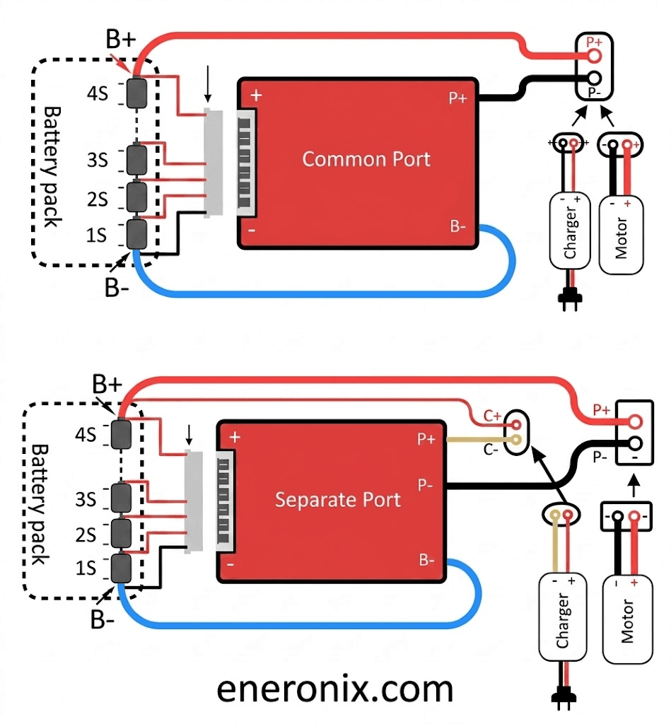
In a common-port BMS, the battery cells connect to the BMS on the cell side through the B+ and B- terminals. Everything else, including the inverter, the MPPT charge controller, and any other load or charge source, connects through a single pair of pack-side terminals: P+ and P-.
Inside the BMS, a single set of power MOSFETs sits between the cells and the P+ terminal. These MOSFETs handle both charge current flowing in from the solar array or grid charger and discharge current flowing out to the inverter and loads.
When any protection function fires, the BMS opens this single MOSFET bank. The P+ terminal becomes electrically isolated from the cells. Nothing can flow in either direction. The battery is completely disconnected from the external circuit until the BMS resets.
The technical term for this is a single-path interrupt. One decision point, one switch, controls everything.
Separate-Port: Independent Control of Each Direction
A separate-port BMS has two independent MOSFET banks. The first controls the charge path: current flowing into the cells from external chargers. This path is accessed through the C+ terminal (charge positive). The second controls the discharge path: current flowing out of the cells to the inverter and loads. This path is accessed through the P+ terminal (discharge positive). Both paths share the same negative terminal.
The BMS firmware can open and close each MOSFET bank independently. An undervoltage event opens the discharge bank while leaving the charge bank closed. An overvoltage event opens the charge bank while leaving the discharge bank closed. An overcurrent discharge event opens the discharge bank only.
This independent control is the entire point. The system can be in a state that was impossible with common-port: protecting the cells from further discharge while simultaneously allowing recovery charging to proceed.
Common-Port vs Separate-Port: Complete Technical Comparison
Parameter
Common-Port BMS
Separate-Port BMS
MOSFET bank configuration
Single MOSFET bank; handles both charge and discharge current
Two independent MOSFET banks; one for charge, one for discharge
Terminal layout
B+/B- (cell side); P+/P- (pack side). One output port.
Opens discharge path for discharge overcurrent; charge path for charge overcurrent independently
Solar recovery after UVP
Requires manual reset or auto-reset timer; solar cannot charge while pack is disconnected
Automatic; solar charging resumes immediately through charge port; pack self-recovers
Wiring complexity
Simple; one positive output terminal
More complex; separate charge and discharge positive terminals must be correctly identified
Risk of wiring error
Low; single output connection
Moderate; C+ and P+ must not be swapped; incorrect wiring can damage BMS
BMS cost
Lower; fewer MOSFETs and gate drivers
Higher; two independent MOSFET banks with separate gate driver circuits
MOSFET reliability
Single bank handles all current in both directions
Each bank handles only one current direction; less thermal stress per bank
Best for
Simple systems; UPS backup; infrequent cycling; systems unlikely to trip UVP under normal operation
Daily-cycling solar systems; off-grid with morning UVP risk; any system where automatic solar recovery is important
Available on JK BMS?
Yes; standard configuration on most variants
Yes; select variants; confirm before purchase
What Actually Happens on Site: Five Fault Scenarios
The table above describes the configurations in the abstract. The fault scenario table below shows what each one actually does when things go wrong in the field. These are the moments that determine whether a system can recover on its own or whether someone has to drive to site.
Fault Scenario
Common-Port BMS Response
Separate-Port BMS Response
UVP at 6am (overnight discharge, weak cell)
BMS opens both MOSFETs. Battery is fully disconnected from inverter and solar. Inverter switches to generator or grid. Solar array produces power but cannot reach the battery. Customer runs on generator until someone manually resets the BMS or auto-reset timer fires.
BMS opens discharge MOSFET only. Inverter loses discharge path. Solar charge path remains open. As sun rises and solar current flows in, the weak cell’s voltage recovers above UVP reset threshold. BMS reconnects discharge path. System resumes normal operation without any manual intervention.
OVP during charging (leading cell hits max voltage)
BMS opens both MOSFETs. Charging stops and loads are disconnected simultaneously. Inverter sees an open circuit and may alarm or switch source.
BMS opens charge MOSFET only. Charging stops. Load discharge path remains active. Loads continue running on battery while the OVP condition resolves through natural cell voltage relaxation.
Sustained overcurrent from inverter load spike
BMS opens both MOSFETs. All loads lose power instantly. May cause sensitive electronics (computers, medical equipment) to shut down abruptly.
BMS opens discharge MOSFET. Loads lose power. Solar charging can continue immediately after OCP resets, charging the battery back up for the next discharge cycle.
BMS charge MOSFET failure (stuck open)
No charging path available. Battery cannot be charged. System is inoperable until BMS is replaced.
Discharge path remains unaffected. Loads continue running. Only charging is lost. Allows a controlled shutdown and BMS replacement without an emergency service call.
BMS discharge MOSFET failure (stuck open)
No discharge path available. Battery cannot supply loads. System is inoperable.
Charge path remains unaffected. Battery can still be charged and maintained at full capacity while discharge MOSFET is repaired. System impact is reduced.
FIELD OBSERVATION
The UVP morning scenario is by far the most common fault situation I encounter in Nigerian off-grid solar installations. A pack that cycled hard the night before, a weak cell that hits UVP before sunrise, a common-port BMS that locks out the solar array at exactly the moment the sun is rising. With good cell matching and active balancing, you reduce the probability of this happening. With a separate-port BMS, you eliminate the consequence when it does happen. Both together is the correct specification.
The Engineering Behind Separate-Port: Why Two MOSFET Banks Cost More
Separate-port BMS units cost more than equivalent common-port units because they genuinely contain more hardware. This is worth understanding so you can evaluate whether a unit claiming separate-port actually has it, or whether the label is being misused.
What Extra Hardware Is Inside
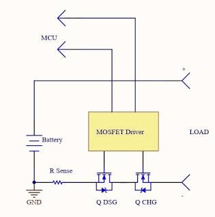
A common-port BMS typically has N-channel MOSFETs arranged in back-to-back pairs on the battery negative line. Two MOSFETs in series, one oriented to block current in each direction. When both are on, current flows in either direction. Opening either one blocks both directions. The gate driver circuit is relatively simple because both MOSFETs are driven by the same logic signal.
A separate-port BMS has two independent MOSFET banks with separate gate driver circuits. The charge path MOSFETs are controlled by one gate driver. The discharge path MOSFETs are controlled by a completely separate gate driver. Each path has its own current sensing, its own overcurrent threshold logic, and its own gate drive timing.
The additional components: a second gate driver IC, additional MOSFETs, separate PCB traces for the charge current path, and the firmware logic to manage two independent states. None of this is expensive in absolute terms, but it adds meaningful cost and PCB area relative to the common-port design.
The upside is reliability. Because charge and discharge current do not flow through the same MOSFETs, each MOSFET bank carries only half the total system current stress compared to a common-port design. In a hybrid solar system where the battery is simultaneously accepting solar charge and supplying loads (net charge or net discharge depending on balance), the common-port BMS is handling bidirectional current with all the associated switching complexity. The separate-port design avoids this entirely.
How to Verify Separate-Port on a Specific BMS Unit
When evaluating a BMS for separate-port, do not rely on marketing descriptions alone. Verify it:
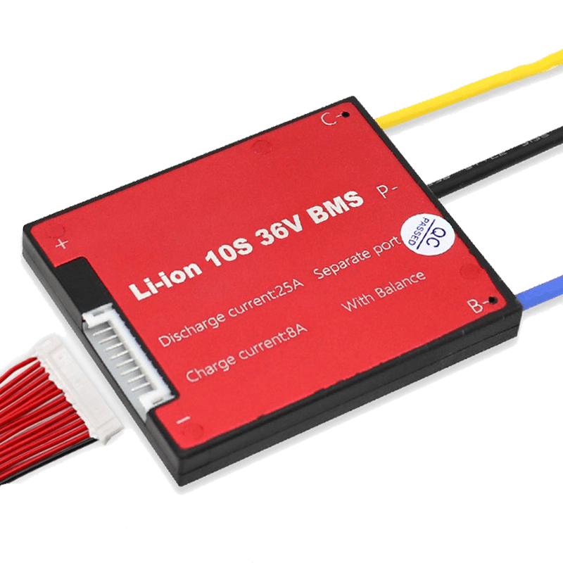
Check the physical terminals. A genuine separate-port BMS has three positive terminals on the pack side: B+ (cell connection), C+ (charge input), and P+ (discharge output). If you see only B+ and P+ with no C+ terminal, it is common-port regardless of what the listing says.
Check the PCB. A separate-port BMS has two physically separate MOSFET banks visible on the PCB. They will be on different areas of the board with separate gate driver ICs feeding them. A common-port board has one bank of MOSFETs, typically in a row, with one gate driver.
Check the datasheet. A proper separate-port BMS datasheet will specify independent charge current rating and discharge current rating, often with different values. If the datasheet lists only a single current rating with no distinction between charge and discharge, it is likely common-port.
Wiring a Separate-Port BMS Correctly
The most common installation error with separate-port BMS units is connecting the inverter to C+ instead of P+, or vice versa. This matters because if you connect the inverter load input to C+, when a load-side overcurrent occurs, the BMS opens the charge path instead of the discharge path. The system loses charging capability instead of load capability. Backwards.
Always follow this rule: loads and the inverter discharge input connect to P+. Charge sources (MPPT charge controller, grid charger) connect to C+. The negative terminal is shared for both.
In a hybrid solar system where the inverter both charges the battery from solar and supplies loads from the battery, the inverter connects to P+ (the discharge port). The inverter internally manages the current direction. The MPPT charge controller, if separate from the inverter, connects to C+. If the inverter handles both solar MPPT and load supply internally (as most hybrid inverters do), all inverter connections go to P+, and C+ may be used for a separate battery charger or left unused.
Terminal
Port Type
Connection Notes
Cell positive (B+)
Both
Connect to first cell positive terminal in series string. This is the raw cell voltage before any MOSFET switching.
Cell negative (B-)
Both
Connect to last cell negative terminal in series string. This is the current sensing and reference side.
Pack positive (P+)
Common-port
Single output terminal. Connect to inverter/load positive bus. Both charge and discharge current flow through this terminal.
Charge positive (C+)
Separate-port
Charge current input only. Connect the positive output of the MPPT charge controller or the inverter’s battery charge output to this terminal. Do NOT connect loads to C+.
Discharge positive (P+)
Separate-port
Discharge current output only. Connect the inverter’s battery input (load side) to this terminal. This is where loads draw current from.
Shared negative
Both
Single negative terminal used for both charge and discharge in separate-port designs. The current sense shunt is typically on the B- line inside the BMS.
RS485 A, B, GND
Both
Communication terminals. Connect to inverter RS485 port. Include GND wire. A and B polarity must match inverter expectation; swap if no communication.
Thermistor connections
Both
NTC thermistors connect to designated thermistor pins on the BMS PCB. Ensure thermistors are in good thermal contact with cell surfaces and MOSFET area.
Cell tap wires
Both
Balance and monitoring wires connect each cell junction to the BMS PCB. Incorrect connection order damages the BMS immediately on power-up. Follow the BMS wiring diagram exactly.
CRITICAL WIRING WARNING
Connecting C+ and P+ to the wrong devices does not immediately destroy the BMS, but it reverses the protection logic. An overcurrent from a load will open the charge MOSFET instead of the discharge MOSFET. The load continues running while the charge path is broken. Depending on the fault conditions, this can lead to cells being drawn below UVP without the discharge protection activating because the BMS fault logic is responding to the wrong port. Wire C+ and P+ correctly before energising the system.
The Morning UVP Scenario: Why This Is the Most Important Use Case
Let me walk through the morning UVP scenario in detail, because it is the single situation that most clearly demonstrates the practical value of separate-port, and it is a situation that occurs regularly in real Nigerian off-grid installations.
The Setup
Off-grid residential installation. 48V 200Ah LiFePO4, Deye 5kVA hybrid inverter, JK BMS (common-port in this scenario). The system has been in service for 8 months. Cell imbalance has been developing slowly because the cells were not perfectly matched at assembly and the passive balancing on this particular BMS variant has not kept pace.
The household runs heavy loads until midnight: television, fans, a chest freezer. By 5:15am, the weakest cell in the pack, cell 9, has reached 2.80V while the other 15 cells are still at 3.05V. The BMS triggers UVP. Both charge and discharge MOSFETs open. The inverter sees an open circuit on the battery port and switches to grid (no grid available in this area, so it shuts down). The house loses power.
With a Common-Port BMS
At 6:00am, the sun rises. The MPPT charge controller starts producing current. It tries to push current into the battery. The BMS charge MOSFET is open. The current cannot reach the cells. The MPPT controller sits at open circuit voltage, producing nothing useful.
At 7:30am, the customer calls. They slept through the outage and woke up with no power. The inverter display shows battery disconnected. The generator is started. You advise a manual BMS reset over the phone, but the customer is not sure where the reset button is. You drive to site. By the time you arrive and reset the BMS, it is 9:30am and three and a half hours of solar generation have been completely wasted.
With a Separate-Port BMS
At 5:15am, the same UVP event occurs. But the separate-port BMS opens only the discharge MOSFET. The charge MOSFET stays closed.
At 6:00am, the MPPT starts pushing current. The current flows through the open charge path directly to the cells. Cell 9 at 2.80V starts accepting charge immediately. The other 15 cells, already at 3.05V, charge slightly faster but the BMS balancer is active and managing the distribution.
By 6:45am, cell 9 has recovered to 3.02V. This is above the BMS UVP reset threshold of 3.00V. The BMS reconnects the discharge MOSFET. The inverter regains its battery source. Power is restored to the house.
The customer wakes up at 7:00am to find everything running normally. They never knew there was a fault event overnight. You get no phone call. You make no site visit.
That is the whole argument for separate-port in one scenario.
The electrochemical reason why weak cells develop in the first place, and how active balancing prevents the accumulation that leads to these morning UVP events, is covered in our article: why lithium batteries go out of balance. Both separate-port and active balancing are part of the same system-level solution.
When Common-Port Is Perfectly Fine
I want to be balanced about this. Common-port BMS is not a bad design. It is the right design for a significant number of applications. Here is when common-port is the correct specification and you do not need the extra complexity or cost of separate-port.
Systems That Never Trip UVP in Normal Operation
If your system is correctly sized with generous battery capacity relative to daily load, shallow depth of discharge, and well-matched actively balanced cells, the probability of a morning UVP event is very low. A system cycling to only 40% depth of discharge daily with a 200Ah pack and active balancing keeping cells within 15mV delta will almost never trip UVP. In that system, common-port behaves identically to separate-port because the scenario where they differ never occurs.
UPS and Backup Systems with Generator Fallback
In a UPS or generator backup application where the battery is only discharged during power outages and is otherwise maintained near full charge, deep discharge events are rare by design. If a UVP event does occur, the generator is already running anyway. The additional recovery capability of separate-port adds little value in this context.
Small Systems with an Operator Present
For a small residential system where the owner is present daily and can perform a manual BMS reset if needed, the operational burden of a common-port trip is manageable. Not ideal, but manageable. For systems in remote locations or commercial sites with uptime commitments, this logic does not apply.
Cost-Constrained Builds Where Every Naira Counts
In a budget-constrained installation where the customer understands the tradeoff and accepts that a UVP event may require a manual reset, specifying common-port to reduce the BMS cost is a legitimate decision. Just make sure both the installer and customer understand what they are trading away.
The Decision Guide: Which Configuration for Which System
Installation Scenario
Recommended Port Config
Rationale
Off-grid home system, 48V 200Ah, daily cycling, Deye or Growatt inverter, Lagos or similar climate
Separate-port
High probability of morning UVP events if cells are not perfectly balanced. Separate-port allows solar self-recovery. Non-negotiable for unattended systems.
Hybrid solar system, 48V 100Ah, moderate daily cycling, customer on site daily
Separate-port preferred; common-port acceptable
Lower UVP risk than deep daily cycling. If customer is present and can reset a trip, common-port is workable. Separate-port is still better practice.
Infrequent cycling means low imbalance accumulation. UVP events are rare. Simpler common-port wiring is appropriate.
Remote off-grid site, 48V 300Ah, deep daily cycling, no operator present
Separate-port, essential
An unattended site with a common-port BMS that trips on UVP and cannot self-recover is a service emergency. Separate-port is not optional here.
Commercial installation, 48V 400Ah+, daily deep cycling, SLA with customer uptime
Separate-port, essential
Customer SLA depends on maximum uptime. Common-port BMS trips that require manual reset violate uptime commitments. Separate-port with automatic solar recovery is a business requirement.
DIY 24V 100Ah pack, backup lighting and fans, occasional use
Common-port adequate
Low duty cycle, shallow cycling, small pack. UVP events are unlikely in normal operation. Common-port is fine and simpler.
DEFAULT POSITION
If you are unsure which to specify, default to separate-port for any system above 100Ah cycling daily. The scenarios where common-port and separate-port behave differently are exactly the scenarios that generate customer complaints and emergency site visits. Separate-port eliminates the most inconvenient class of BMS fault response at a cost premium that is easily justified by avoiding a single unnecessary site visit.
A Note on JK BMS Port Configuration
Since the JK BMS active balancer series is the most commonly recommended BMS in this cluster, it is worth addressing the port configuration question specifically.
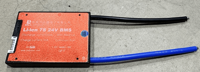
The standard JK BMS B2A24S20P is a common-port unit. This is the version you will find in most Nigerian solar equipment stores and the version most commonly shipped by Chinese distributors. The separate-port variant exists in the JK BMS product range but is less common in the Nigerian market and may require a specific order from a specialist supplier.
For most Nigerian installations using a Deye, Growatt, or Solis hybrid inverter, the common-port JK BMS is what is installed. In practice, whether this causes problems depends on how the system is designed and operated:
If the system has active balancing keeping cells tightly matched and the daily cycling does not push the weakest cell near UVP, common-port JK BMS works without issue for years.
If the system is pushing cells hard daily, has older or less-matched cells, or is in a remote location where a UVP trip would require a site visit, specifying the separate-port variant or planning for an alternative auto-recovery mechanism is the right call.
For Pylontech batteries, the separate-port question does not apply. The integrated Pylontech BMS manages charge and discharge paths according to Pylontech’s own internal design, which is optimised for the Pylontech cell chemistry and cycling profile. The user does not configure port type on a sealed Pylontech unit.
What Most Installers Get Wrong About Port Configuration
MISTAKE 1
Not knowing what port type the BMS is before installing it. Most installers in Nigeria never think about this. They connect the BMS, wire the inverter to P+, and call it done. If it is common-port, that is fine. If it was supposed to be separate-port and they do not have one, they just installed a system that will lock out solar during morning UVP events without knowing it. Check the terminal layout before wiring, not after.
MISTAKE 2
Connecting the MPPT charge controller to P+ instead of C+ on a separate-port BMS. The MPPT connects to C+. The inverter load side connects to P+. Reversing this means the BMS’s independent path control is wired backwards. When a load overcurrent fires, the charge path opens instead of the discharge path. The system continues to run on battery while the solar array is disconnected. This is both inefficient and dangerous if the overcurrent is from a genuine fault.
MISTAKE 3
Assuming separate-port eliminates the need for active balancing. It does not. Separate-port solves what happens after a UVP trip. Active balancing reduces the probability of a UVP trip by keeping cells matched. Both are part of a correctly specified system. Separate-port with passive balancing will still see regular UVP trips on a 200Ah daily-cycling pack within 18 months as cells diverge. The solar recovery will be automatic, but the trips will still happen.
MISTAKE 4
Treating the morning UVP recovery as proof the system is healthy. A system that regularly trips UVP and recovers via the separate-port charge path is sending a clear signal that cell imbalance has grown to a level where the weakest cell is routinely being deep discharged. Separate-port handles the recovery gracefully, but it does not solve the underlying problem. When UVP trips start occurring regularly, open the BMS app, read the cell voltages, identify the weak cell, and investigate whether it needs a full balancing session or replacement.
What is the difference between common-port and separate-port BMS?
A common-port BMS routes both charge and discharge current through a single pair of output terminals and a single set of MOSFET switches. When any protection function trips, both charge and discharge paths open at the same time. A separate-port BMS has dedicated charge input terminals controlled by their own MOSFET bank, and separate discharge output terminals controlled by a different MOSFET bank. This allows the BMS to open the discharge path while leaving the charge path active, or vice versa. In solar storage applications where you want the battery to continue accepting solar charge during a low-voltage protection event, separate-port is the correct configuration.
Which is better for solar storage, common-port or separate-port BMS?
Separate-port is generally better for solar storage applications where the battery cycles daily and where the solar array continues producing power during morning hours when the battery may be in a low-voltage protection state. With a common-port BMS, a UVP trip at 6am disconnects the battery from everything including the solar array. With a separate-port BMS, solar charging continues and the battery self-recovers without manual intervention. For simple non-solar applications or small systems with infrequent cycling, common-port is adequate and simpler to wire.
Can a common-port BMS charge and discharge at the same time?
A common-port BMS uses the same terminals for both charge and discharge, so technically charge current and discharge current flow through the same port. In a hybrid solar system where the inverter both charges the battery from solar and draws from it for loads, the inverter manages this internally and connects to the single common port. The BMS sees net current flow: if charging exceeds load demand, current flows in. If load exceeds charge, current flows out. The BMS manages both directions through the same MOSFET bank.
What happens when a separate-port BMS trips on UVP?
When a separate-port BMS detects that a cell has reached the UVP threshold, it opens the discharge MOSFET bank only. The charge MOSFET bank remains closed. The inverter loses its discharge path from the battery, which triggers a low-battery alarm or switches to another power source. But the solar array can still push current through the charge port into the cells. As cells recover above the UVP reset threshold, the BMS reconnects the discharge path automatically. The system self-recovers without a manual reset.
Does separate-port BMS affect how I wire my solar system?
Yes. With a separate-port BMS, the charge current and discharge current travel through different physical terminals on the BMS. The MPPT charge controller or inverter’s battery charge output connects to the BMS charge port (C+ and shared negative). The inverter’s battery discharge input, or the load bus, connects to the BMS discharge port (P+ and shared negative). In most hybrid inverter systems where the inverter handles both charging and discharging, it connects to the P+ discharge port, and the charge controller connects to C+. Always refer to the specific BMS wiring diagram for your model.
Is the JK BMS common-port or separate-port?
The standard JK BMS active balancer series (B2A24S20P and similar) is common-port by default. Separate-port variants are available in the JK BMS product range but are less common in the Nigerian market. If separate-port is a design requirement for your system, confirm the specific model variant before purchasing. The product listing should explicitly state separate-port or two-port configuration. If it shows only B+ and B- on the cell side and P+ and P- on the pack side with no C+ terminal, it is common-port.
Can I convert a common-port BMS to separate-port?
No. The port configuration is determined by the PCB layout and MOSFET bank arrangement inside the BMS. A common-port BMS cannot be converted to separate-port without a different PCB design. If you need separate-port functionality and your current BMS is common-port, you need a different BMS unit. This is a specification decision that should be made before purchase, not after installation.
When does it not matter whether I use common-port or separate-port?
For systems that do not experience UVP protection events in normal operation, the difference is rarely triggered and therefore rarely matters. A system with generous battery capacity relative to daily load, shallow depth of discharge, and well-balanced cells may never trip UVP under normal conditions. In that case, common-port and separate-port behave identically. The separate-port advantage only becomes visible when a protection event actually occurs. Since you cannot always predict whether protection events will occur, separate-port is the safer default specification for any daily-cycling solar storage system.
I am Engr. Ubokobong Ekpenyong, a solar specialist and lithium battery systems engineer with over five years of hands-on experience designing, assembling, and commissioning off-grid solar and energy storage systems. My work focuses on lithium battery pack architecture, BMS configuration, and system reliability in off-grid and high-demand environments.
Contains information related to marketing campaigns of the user. These are shared with Google AdWords / Google Ads when the Google Ads and Google Analytics accounts are linked together.
90 days
__utma
ID used to identify users and sessions
2 years after last activity
__utmt
Used to monitor number of Google Analytics server requests
10 minutes
__utmb
Used to distinguish new sessions and visits. This cookie is set when the GA.js javascript library is loaded and there is no existing __utmb cookie. The cookie is updated every time data is sent to the Google Analytics server.
30 minutes after last activity
__utmc
Used only with old Urchin versions of Google Analytics and not with GA.js. Was used to distinguish between new sessions and visits at the end of a session.
End of session (browser)
__utmz
Contains information about the traffic source or campaign that directed user to the website. The cookie is set when the GA.js javascript is loaded and updated when data is sent to the Google Anaytics server
6 months after last activity
__utmv
Contains custom information set by the web developer via the _setCustomVar method in Google Analytics. This cookie is updated every time new data is sent to the Google Analytics server.
2 years after last activity
__utmx
Used to determine whether a user is included in an A / B or Multivariate test.
18 months
_ga
ID used to identify users
2 years
_gali
Used by Google Analytics to determine which links on a page are being clicked
30 seconds
_ga_
ID used to identify users
2 years
_gid
ID used to identify users for 24 hours after last activity
24 hours
_gat
Used to monitor number of Google Analytics server requests when using Google Tag Manager
1 minute
You can find more information in our Cookie Policy and .

")


")


