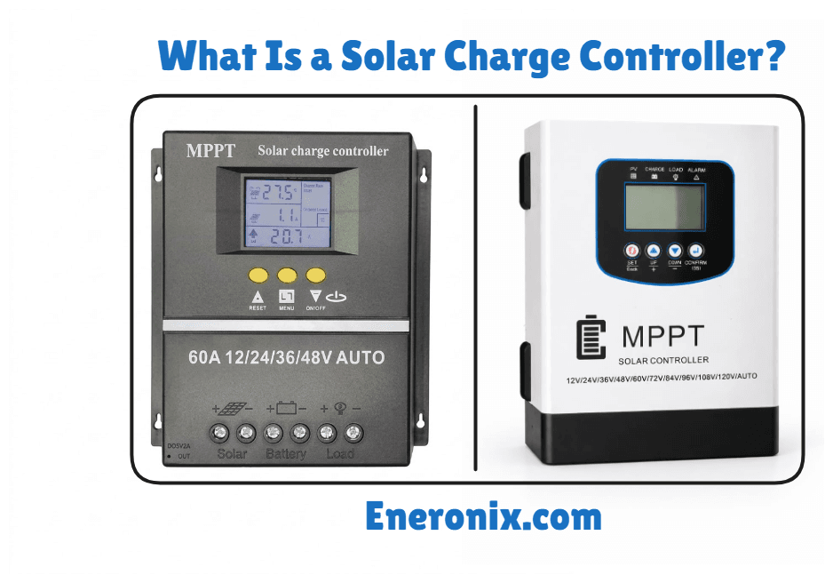
What Is a Solar Charge Controller?
Solar panels produce raw, unregulated power. The voltage changes with cloud cover, time of day, and temperature. If you connect PV panels directly to a battery bank, that uncontrolled voltage will go into the battery cells without any limit. This will overcharge them, cause them to overheat, and in most cases, shorten the battery life faster than almost any other mistake you can make in an off-grid system.
A solar charge controller sits between your solar panels and your battery bank. Its job is to regulate the voltage and current flowing from the solar array so your batteries charge safely and last as long as they should.
If you are designing or buying a solar system, you need to understand more than the short answer. You need to know what a charge controller actually does inside a system, how it protects your batteries, what the difference between MPPT and PWM really means, and what specs matter before you spend any money.
This article covers all of that. If you already know the basics and want to go straight to the MPPT vs PWM comparison, there is a dedicated article on MPPT and PWM
What Is a Solar Charge Controller?

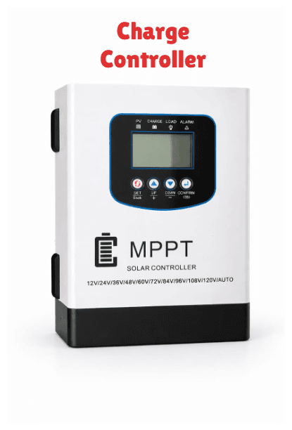
A solar charge controller is an electronic device that regulates the voltage and current coming from your solar panels before it reaches your battery bank. That is the technical definition. The practical one: it is the gatekeeper between your panels and your batteries.
When the sun is up, your panels are producing power. That power needs to get into your batteries at the right rate. Too much voltage and the battery overcharges. Too little regulation and the charging process becomes inefficient. The controller manages both problems continuously, all day, every charging cycle.
Here is why panels cannot connect directly to batteries. A standard solar panel on a 12V system might have an open-circuit voltage (Voc) of 20V to 22V. A 12V lead-acid battery charges at around 14.4V. Without a controller in between, the panel pushes whatever voltage it produces straight into the battery. That excess voltage has nowhere to go except into the cells as heat and gas. With a lithium battery, the consequences are faster and more severe.
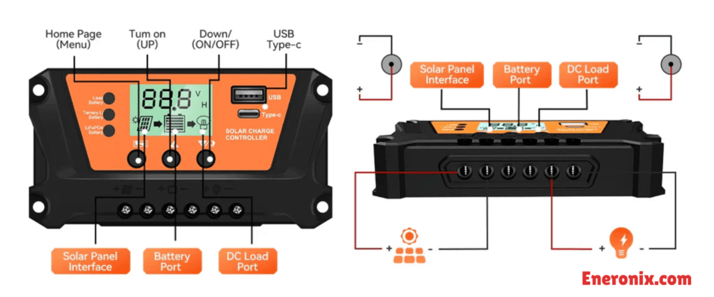
The controller also manages a load output on many models. This is a separate DC terminal that powers small loads like lights or fans directly, with its own low-voltage disconnect to protect the battery from being drained too deep. Not all controllers have this, and on larger systems it is rarely used, but it is worth knowing it exists.
A charge controller is not an inverter, not a BMS, and not a power optimizer. It does one job: managing the DC charging path from panels to battery. Anything beyond that is a different device.
Where a Charge Controller Fits in a Solar System
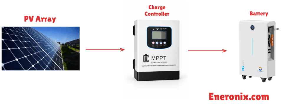
In a standard off-grid DC-coupled system, the sequence is: solar array, charge controller, battery bank, inverter, AC loads. The controller manages only the charging path between the array and the battery. It has no visibility into battery discharge, inverter behavior, or AC load consumption.
Most standalone off-grid installations in Nigeria follow this topology. The panels feed the controller, the controller feeds the battery, and the inverter draws from the battery independently.
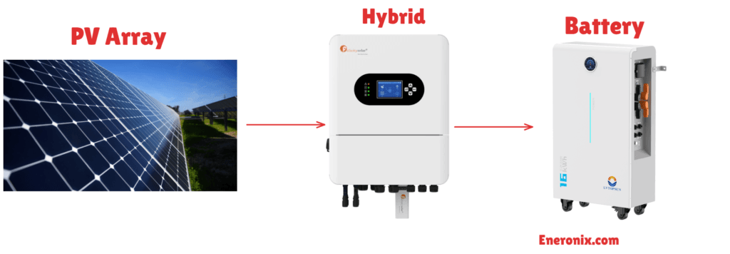
Some modern hybrid inverters, including the Deye and Growatt SPF series, integrate an MPPT charge controller internally. In those systems, the panels connect directly to the inverter’s PV input terminals, and no external charge controller is installed. If you are running one of those units, the charge controller function is handled inside the inverter. The hybrid solar system wiring guide covers that topology in detail.
For systems using a standalone inverter/charger without a built-in MPPT, an external charge controller is a separate device on the DC charging path.
The controller’s scope is strictly limited to regulating current and voltage into the battery during charging hours. It does not manage loads, does not communicate with the inverter in most standard configurations, and does not monitor the battery’s state of charge during discharge.
How a Charge Controller Protects Your Battery
The charge controller’s primary job is battery protection. Voltage regulation is the mechanism. Battery survival is the outcome. That distinction matters because buyers often treat the controller as a minor accessory, when it is actually the device standing between a functional battery bank and an expensive failure.
Overcharge protection
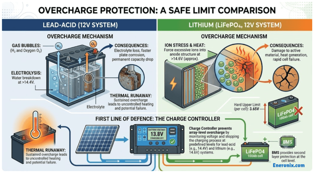
A lead-acid battery at full charge has a specific voltage ceiling it cannot safely exceed. On a 12V system, that ceiling sits around 14.4V. Push charging voltage beyond that threshold and the excess energy drives electrolysis inside the battery, breaking down water in the electrolyte into hydrogen and oxygen gas. The battery loses electrolyte, plates corrode faster, and capacity drops permanently. If the overcharge is sustained, internal temperature rises, resistance drops, and the battery absorbs even more current, raising temperature further. That feedback loop is thermal runaway.
With lithium batteries the tolerance for overcharge is narrower and the consequences are faster. LiFePO4 cells have a hard upper voltage limit per cell, typically 3.65V. Excess voltage forces more lithium ions into the anode than the electrode structure can accommodate, damaging the active material and generating heat. A BMS provides a second layer of protection at the cell level, but the charge controller is the first line of defence at the array level, preventing that condition from occurring in the first place. The BMS protection explained article covers what happens at the cell level in detail.
Reverse current protection
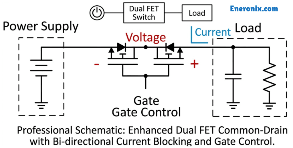
At night, the voltage difference between panels and batteries reverses. Panels drop to near zero volts while the battery holds its resting voltage. Without a blocking mechanism, current flows backwards out of the battery and into the panel, slowly discharging the bank overnight. The charge controller contains a blocking diode or MOSFET switch that prevents this reverse flow the moment panel voltage drops below battery voltage.
Temperature compensation
Battery charging voltages are calibrated at 25 degrees Celsius. As temperature rises above that reference point, a lead-acid battery’s internal resistance drops, meaning it accepts more current at any given voltage than it should. The correct response is to lower the charge voltage slightly to match.
For a 12V lead-acid system, the typical compensation rate is around 3mV per cell per degree Celsius. A 12V battery has six cells, so the adjustment is approximately 18mV per degree. At 40 degrees ambient, which is not unusual for a battery enclosure in Lagos during harmattan season, that adjustment pulls the bulk charge voltage down by roughly 0.27V. A controller without temperature compensation charges at the factory setpoint regardless of ambient heat, which means it is chronically overcharging batteries during the hottest months of the year.
Most quality controllers accommodate this with either an external temperature sensor that mounts directly on the battery, or an internal sensor that reads enclosure temperature as a proxy. The external sensor is more accurate. LiFePO4 batteries handle temperature variation differently and most lithium BMS units manage their own thermal protection. The charge controller’s temperature compensation is primarily relevant for lead-acid installations.
Low-voltage disconnect (LVD)
Controllers with a load output terminal include a low-voltage disconnect function. When battery voltage drops to a set threshold, typically 11.1V on a 12V system, the controller cuts power to the load output to prevent the battery from discharging further. Loads reconnect automatically once the battery recovers to a recovery voltage, usually around 12.5V.
LVD only protects loads connected to the controller’s dedicated load terminal. Loads connected directly to the battery, or through an inverter, are not covered. In a Lagos residential installation where a 400Ah to 600Ah lithium bank costs between NGN 400,000 and NGN 600,000, a correctly configured charge controller and BMS combination is significantly cheaper than a replacement battery bank after two years of unregulated charging.
Types Of Solar Charge Controller: MPPT vs PWM
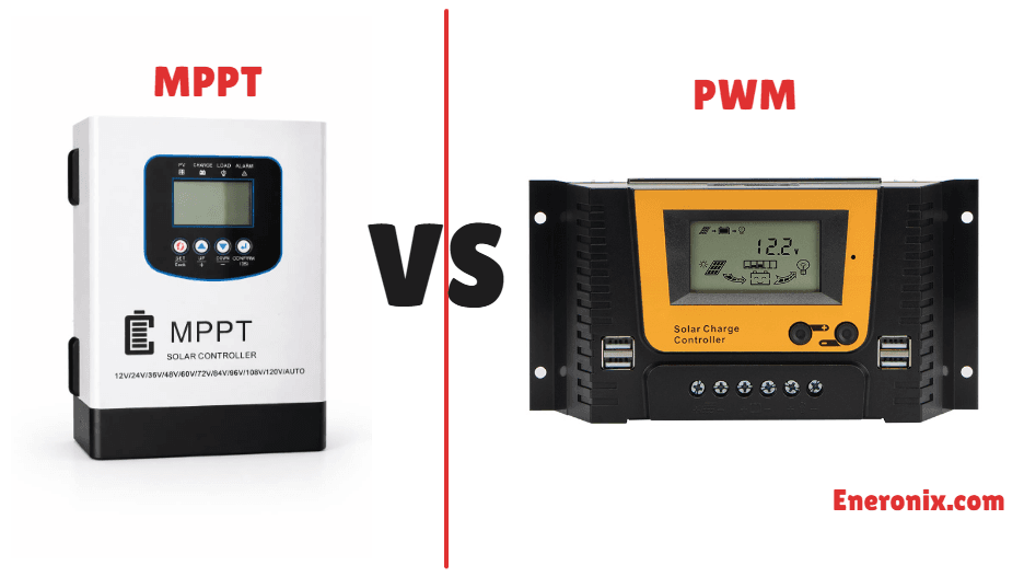
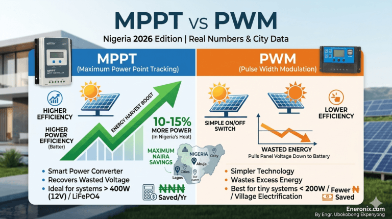
All solar charge controllers fall into one of two technology categories: PWM or MPPT. The difference between them is not just efficiency on paper. It determines how much of your panel’s rated output actually reaches your battery, and that gap widens significantly as system size grows.
PWM (Pulse Width Modulation)
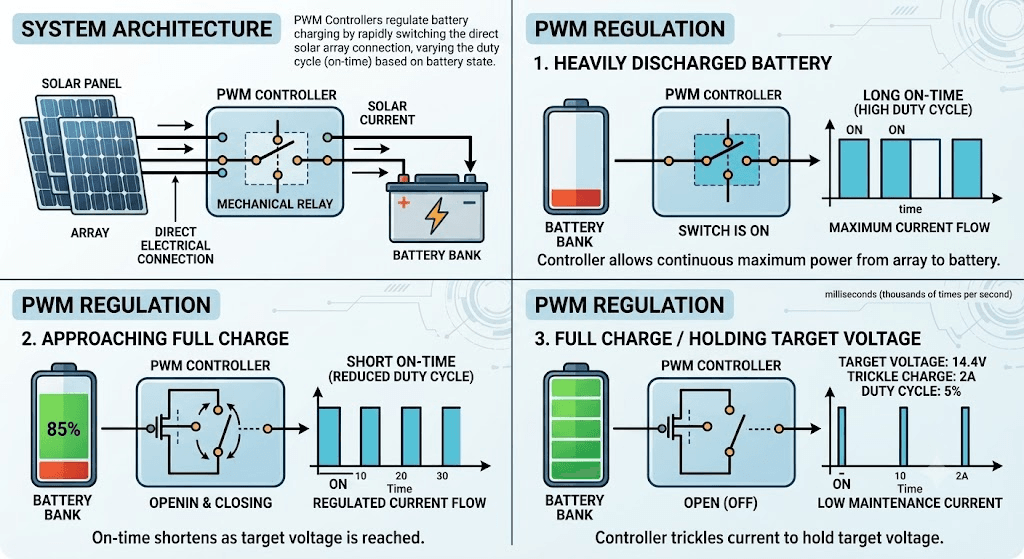
A PWM controller makes a direct electrical connection between the solar array and the battery bank. It regulates charging by switching that connection on and off thousands of times per second, varying how long the connection stays open per cycle. When the battery is heavily discharged, the switch stays on longer, allowing maximum current through. As the battery approaches full charge, the on-time shortens until the controller is just trickling enough current to hold the battery at its target voltage.
The fundamental limitation is voltage. Because the panel connects directly to the battery, the controller pulls the panel’s operating voltage down to match the battery voltage. A panel with a maximum power point voltage (Vmp) of 36V connected to a 12V battery through a PWM controller gets dragged down to operate around 14V. The power that panel could have delivered at 36V is never harvested.
PWM controllers make sense in specific, limited scenarios: systems under 400W, 12V nominal battery banks, and panel strings where the Vmp sits close to the battery’s charging voltage. In those conditions, the voltage mismatch is small and the efficiency loss is manageable. The cost saving over MPPT is real for small setups.
MPPT (Maximum Power Point Tracking)
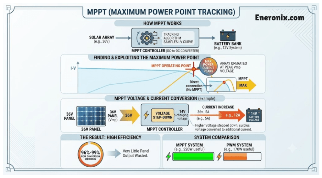
An MPPT controller is a DC-to-DC converter with a tracking algorithm built in. Rather than connecting the panel directly to the battery, it samples the panel’s voltage and current relationship continuously, finds the point on the I-V curve where power output peaks, and operates the array at that voltage. It then steps that higher voltage down to the battery’s charging voltage while converting the surplus voltage into additional charging current.
The result is that a 36V panel feeding a 12V battery through an MPPT controller operates at its actual Vmp. The controller steps 36V down to 14V and the current at the battery terminals increases proportionally. Very little of the panel’s potential output is wasted. Peak conversion efficiency on quality MPPT units runs between 96% and 99%.
The efficiency advantage over PWM in real-world field conditions typically falls between 10% and 30%, depending on the voltage mismatch between the array and battery bank, ambient temperature, and irradiance levels. In Nigeria’s climate, where ambient temperatures are consistently high, the cold-weather advantage of MPPT is less pronounced than in temperate regions. However, the voltage mismatch gain remains significant for any system running 24V or 48V battery banks with modern 400W+ panels, which have Vmp values typically between 38V and 42V.
The decision rule
If your panel string’s open-circuit voltage is significantly higher than your battery bank voltage, MPPT converts that gap into usable energy. PWM discards it as heat. Above 400W of array capacity, on any 24V or 48V system, or with a lithium battery bank of any size, MPPT is the correct choice.
The full technical comparison, including sizing calculations and side-by-side performance data for Nigerian conditions, is in the dedicated MPPT vs PWM charge controller guide.
How Charging Stages Work
The charge controller does not just push current into a battery until it is full. It manages the charging process in defined stages, each with a specific voltage target and current behaviour. The controller executes these stages. The battery responds to them.
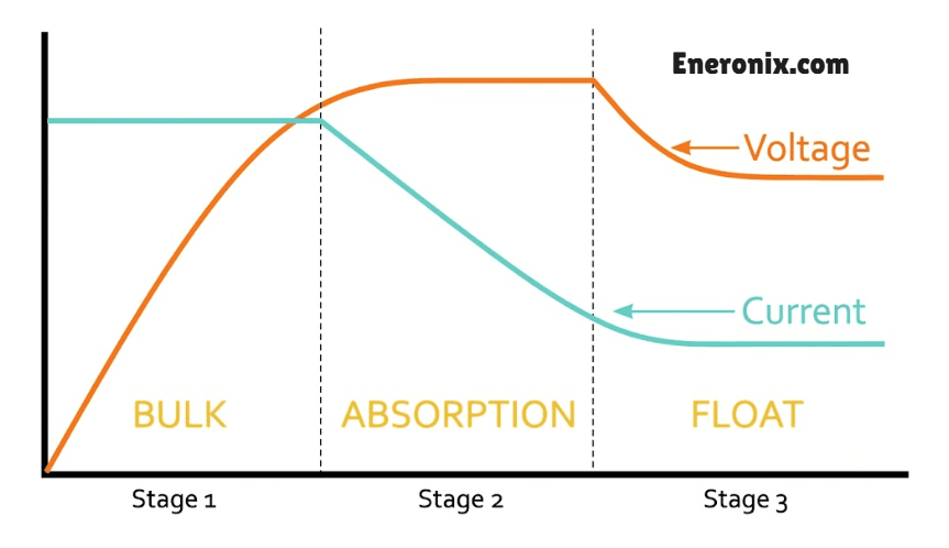
Bulk stage
When the sun comes up and the battery is below its target voltage, the controller opens the charging path and allows maximum available current to flow. The battery voltage rises steadily throughout this stage. For a 12V lead-acid system, bulk continues until the battery reaches approximately 14.4V. On a 24V system, that target doubles to 28.8V.
Bulk is where the majority of the energy goes in. Depending on how deeply the battery discharged overnight, this stage typically restores around 70 to 80 percent of capacity. The controller doesn’t throttle current here. It delivers whatever the array can produce up to its rated output.
Absorption stage
Once the battery hits the bulk voltage setpoint, the controller locks voltage at that level and holds it there. Current naturally tapers as the battery fills, because a fuller battery offers higher internal resistance to incoming charge. The controller isn’t reducing current directly. The battery chemistry is doing it.
Absorption ends either after a fixed time period, when a timer expires, or when current drops below a threshold value called the tail current. On Victron SmartSolar controllers, the default tail current is 2A. Other brands use time-based termination. Neither method is universally superior. Time-based works reliably for lead-acid. Current-based termination is more precise for lithium.
This stage pushes the battery from roughly 80 percent to full. Skipping or shortening absorption results in a battery that never fully charges, even if the display reads 100 percent. Cell imbalance accumulates over time in a pack that chronically misses full absorption.
Float stage
After absorption completes, the controller drops voltage to a lower maintenance level, typically around 13.6V on a 12V system. At this voltage, the battery sits without gaining or losing significant charge. The controller compensates for natural self-discharge and any small parasitic loads drawing from the system.
Lead-acid batteries self-discharge at a meaningful rate and need float to stay topped up. LiFePO4 batteries self-discharge at roughly 2 percent per month, which is low enough that continuous float charging provides no real benefit. More relevant, holding a lithium pack at sustained high voltage accelerates cell aging. Quality controllers allow float to be disabled for lithium systems, or set to a low standby voltage that only activates when the battery drops to a defined restart threshold. If your controller doesn’t offer this, set float voltage to match the battery’s resting voltage, around 13.4V to 13.5V for a 12V LiFePO4 pack, to minimise the impact. The dedicated article on why lithium batteries don’t need float charging covers this in full.
Equalization stage
Equalization is a periodic controlled overcharge applied to flooded lead-acid batteries only. Over time, the electrolyte in a flooded cell stratifies, with heavier acid settling toward the bottom of the battery. Sulphation also builds on the plates. A brief charge at elevated voltage, typically 15.0V to 15.5V on a 12V system, generates gas bubbles that stir the electrolyte and break down sulphate deposits.
This stage should run for two to four hours, scheduled monthly or triggered manually. It is never appropriate for AGM, Gel, or any lithium chemistry. AGM batteries have no free electrolyte to stir, and the elevated voltage simply damages the plates. On lithium, equalization voltages push individual cells above their hard upper limit and will either trigger the BMS to disconnect or, if the BMS fails to respond, degrade the cells directly.
One of the most common and expensive mistakes in Nigerian installations is running a lithium battery on a controller still set to a lead-acid or default profile. The voltage setpoints are wrong across all three stages, equalization may fire automatically, and the battery degrades faster than it should while appearing to work normally. Before connecting any controller to a lithium pack, verify the charge profile settings match the battery manufacturer’s specifications. The lead-acid vs lithium charging differences article covers the exact profile differences in detail.
Key Specifications to Understand Before Buying
Every charge controller has four numbers that determine whether it will work safely in your system. Get any one of them wrong and you either destroy the controller, bottleneck the array, or both.
1. Maximum PV input voltage (Voc rating)
This is the highest voltage the controller can accept at its solar input terminals. Exceed it and the input stage fails, typically immediately and permanently, with no warranty coverage.
The danger is that panel open-circuit voltage (Voc) is not fixed. It rises as temperature drops. A panel with a Voc of 42V at 25°C will produce a higher voltage on a cold morning. In Nigeria’s climate, cold-weather Voc spikes are less severe than in temperate countries, but panels in series multiply the risk. Two 400W panels wired in series, each with a Voc of 42V, produce a combined Voc of 84V. On a controller rated at 75V maximum input, that string will destroy the unit.
The standard safety practice is to apply a 1.25x multiplication factor to your calculated string Voc and ensure the result sits below the controller’s rated maximum. For Lagos installations where ambient temperatures rarely drop below 20°C, this margin is conservative but still worth maintaining, especially as panel Voc can spike briefly under certain irradiance conditions.
2. Maximum PV input current (Isc rating)
This is the maximum short-circuit current the controller can accept from the array. Short-circuit current (Isc) is the highest current a panel produces under direct short conditions and is listed on every panel’s datasheet.
Exceeding the Isc rating doesn’t always destroy a controller instantly, but it causes the unit to run continuously above its thermal design limit. In an already hot environment, an undersized controller running at thermal ceiling degrades faster than its rated lifespan, often failing within the first or second year. Size with a 1.25x safety factor on your array’s total Isc as well.
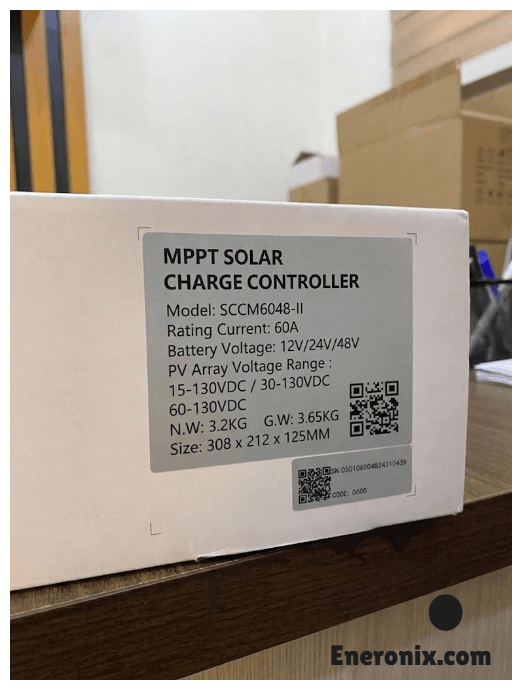
3. System voltage (12V / 24V / 48V)
The controller must be configured to match your battery bank’s nominal voltage. Most quality MPPT controllers, including the Epever Tracer and Victron SmartSolar range, auto-detect system voltage at startup. Budget units often do not. Check before assuming.
The choice of system voltage also matters beyond the controller. For the same power output, a 48V system carries one-quarter the current of an equivalent 12V system. Lower current means thinner DC cables, smaller fuses, less resistive loss in the wiring, and less heat generated across the whole DC circuit. A 3kW load on a 12V system pulls 250A. The same load on a 48V system pulls 62.5A. The difference in required cable cross-section, and the cost of that copper, is significant. For any new residential off-grid installation in Nigeria above 1kW of array capacity, 48V is the right starting point. The DC cable sizing guide covers the full calculation.
4. Output current rating (amps)
This is the charging current the controller delivers to the battery bank. It is also the number most buyers use to compare controllers, and for good reason. It directly determines how fast your battery bank charges.
The quick sizing calculation: multiply the controller’s output current rating by the system voltage to get the maximum array wattage the controller can handle. A 40A controller on a 48V system handles up to 1,920W of array. A 60A controller on the same bank handles up to 2,880W. Feed more array wattage than the controller’s rated capacity and it simply caps output at its maximum current rating. You lose energy harvest that your panels could have delivered.
These four specifications are the minimum you need to match a controller to your system correctly. The full sizing walkthrough, including worked examples for common Nigerian system sizes, is in the MPPT controller sizing guide.
What a Charge Controller Does NOT Do
Understanding the boundaries of a charge controller prevents the kind of wiring decisions and purchasing mistakes that are difficult and expensive to reverse.
It does not replace a BMS on lithium batteries
A charge controller operates at the array level. It monitors the battery bank’s terminal voltage and adjusts charging current accordingly. What it cannot see is what’s happening inside the pack: individual cell voltages, cell temperature, state of balance, or internal faults.
A LiFePO4 battery pack with four cells in series might show 13.8V at the terminals while one cell has drifted to 3.8V and another sits at 3.0V. The charge controller reads 13.8V and sees nothing wrong. The BMS, monitoring each cell individually, catches that imbalance and responds. The charge controller and the BMS are not doing the same job. Both are necessary. The BMS protection explained article covers the cell-level functions in detail.
It does not regulate AC loads
Once power leaves the battery and enters the inverter, the charge controller has no involvement. It cannot see how much power your inverter is drawing, cannot shed loads when the battery drops, and cannot communicate with the inverter in a standard off-grid configuration. Load management on the AC side belongs to the inverter or to a separate energy management device.
It does not function as an inverter
A charge controller handles DC only. It does not convert battery DC to AC. In the market, this confusion comes up regularly because combo units, inverter/chargers with a built-in MPPT stage, are sold as single boxes. Those are two separate functions sharing one enclosure. If the MPPT stage fails, the inverter function typically continues. They are distinct circuits that happen to be packaged together.
It does not increase battery capacity
A correctly sized and configured controller maximises the energy harvested from your array. It does not create storage that isn’t there. If your battery bank is undersized for your load, a better controller will not solve that problem. Sizing the battery bank correctly comes first. The battery bank sizing guide covers that calculation.
It does not work reliably without a battery in most configurations
Most PWM controllers and the majority of MPPT controllers use the battery as the voltage reference point for regulation. Without a battery connected, the controller has no stable reference to regulate against. Panel voltage becomes uncontrolled at the output terminals, which can spike well above safe limits for any load connected downstream. Some advanced MPPT units, including certain Epever models, include a battery-free load output mode, but this is an exception and is not a substitute for a properly designed battery-based system.
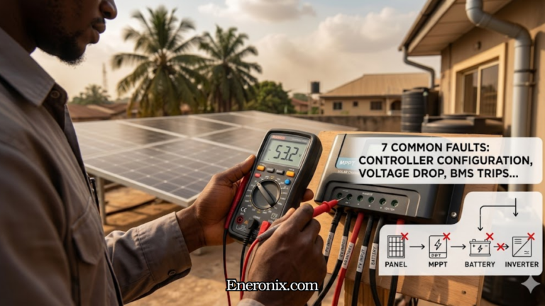
Signs Your Charge Controller Is Failing
Most charge controller problems show up as battery behaviour problems first. The controller fails quietly while the battery takes the damage visibly.
Battery never reaches full charge
If the controller display shows bulk charging hours into a clear sunny day, or the battery voltage never climbs to the absorption setpoint, the MPPT tracking algorithm may have failed, the absorption voltage setpoint may have drifted, or the input stage is no longer converting panel power efficiently. Before blaming the controller, rule out panel output issues by measuring PV voltage and current at the controller’s input terminals with a multimeter.
Battery overcharging
Voltage climbing above the absorption setpoint and staying there is a controller fault until proven otherwise. Check the battery profile settings first. A unit mistakenly left on an equalization schedule, or with an incorrectly high bulk voltage, will push the battery beyond its limits on every sunny day. If the settings are correct and overcharging continues, the voltage regulation circuit inside the controller has likely failed.
Controller running hot or shutting down on thermal protection
Charge controllers generate heat during normal operation, but a unit that is consistently too hot to touch or that shuts down during peak sun hours is either undersized for the array, poorly ventilated, or operating above its rated ambient temperature. In Lagos, where enclosure temperatures can reach 45 to 50 degrees Celsius during dry season afternoons, a controller rated to a maximum of 45 degrees ambient needs to be mounted in a shaded, ventilated space. Heat is the primary reason cheap controllers fail within the first two years in Nigerian installations.
Error codes on the display
Quality controllers from Epever, Victron, and Renogy display fault codes that point directly to the problem. An over-temperature code is not a hardware failure on its own. It is the controller protecting itself and telling you to fix the installation environment. An over-voltage code on the PV input means your string Voc is exceeding the controller’s rated maximum, which is a wiring or configuration problem. Read the error code, consult the manual, and address the root cause rather than simply resetting the unit.
Zero or very low PV input voltage on a sunny day
If the controller shows no solar input during clear conditions, start at the fuse or breaker between the array and the controller. A blown fuse is the most common cause and takes two minutes to check. If the fuse is intact, inspect terminal connections for corrosion or looseness. Corroded MC4 connectors at panel junction boxes are a frequent culprit in humid coastal environments.
Rapid cycling between charge states
A controller that flips from bulk to float and back repeatedly within minutes is almost never a controller hardware fault. Loose connections at the battery terminals create momentary voltage spikes that the controller reads as the battery reaching full charge, then dropping again. Tighten every terminal in the DC circuit before looking at the controller itself.
For detailed diagnosis procedures on each of these symptoms, the full troubleshooting guide is available in the off-grid solar systems commissioning and troubleshooting article.
Nigeria Buyer Note
Brands available in Lagos, Abuja, and Port Harcourt
The most commonly stocked MPPT controllers in the Nigerian market are Epever Tracer series, Victron SmartSolar, and a range of generic Chinese units sold under brands like SRNE, Suoer, and various unbranded clones. Renogy Rover units appear occasionally through online platforms. For PWM controllers, the market is dominated by generic brands sold through Jumia, Jiji, and Alaba International Market.
Approximate price bands (as of mid-2026, subject to exchange rate movement)
| Type | Capacity | Approx. Price Range |
|---|---|---|
| Generic PWM | 30A | ₦8,000 — ₦22,000 |
| Mid-range MPPT (Epever Tracer) | 40A | ₦80,000 — ₦150,000 |
| Mid-range MPPT (Epever Tracer) | 60A | ₦350,000 — ₦420,000 |
| Premium MPPT (Victron SmartSolar) | 60A+ | ₦400,000 — ₦1,000,000+ |
The single most common and costly mistake
Pairing a 2kW to 4kW array with a 20A or 30A controller because it was cheaper at the point of sale. A 30A controller on a 48V system handles a maximum of 1,440W. Feed it 3kW of panels and it runs at continuous thermal overload from the first sunny day. In Nigeria’s heat, that unit typically fails within six to twelve months. The battery does not get fully charged in the interim, and the replacement controller costs more than the savings made upfront.
Beware of clones
Epever is heavily cloned in the Nigerian market. Clone units use the same casing and display design but run inferior MPPT algorithms that track poorly and often misreport system data. Buy from verified distributors. SolarKobo, Solar Depot Nigeria, and Kara carry confirmed original Epever stock. For Victron, purchase only through Victron-certified distributors. Victron maintains a distributor list on their website at victronenergy.com.
Where to buy
Physical stock: Computer Village Ikeja, Alaba International Market, and solar-specific outlets in Lagos carry Epever and generic brands. Victron and premium MPPT units are best sourced through certified distributors rather than open market traders, where counterfeit risk is higher.
Frequently Asked Questions
Do I need a charge controller with every solar panel?
For any real-world battery-based system, yes. The only exception is a very small panel, typically under 5W, trickle-charging a large battery bank where the current is too low to cause overcharge under any condition. A 100W panel connected directly to a battery without a controller will damage the battery within weeks. Grid-tied systems without battery storage do not need a charge controller at all since the grid manages the power flow.
Can a solar panel charge a battery without a charge controller?
Physically, yes. Safely, no. A panel producing 20V to 22V connected directly to a 12V battery pushes unregulated voltage into the cells continuously. The battery overcharges, electrolyte boils off in lead-acid, and the battery’s capacity drops permanently. At night, the same panel becomes a load and pulls current back out of the battery. A charge controller costs a fraction of a battery bank. Skipping it to save money is one of the more expensive decisions in off-grid solar.
Can one charge controller handle multiple batteries?
Yes. Multiple batteries wired in parallel are seen by the controller as a single larger battery at the same nominal voltage. The controller does not need to change or be reconfigured. What changes is the battery bank’s total capacity and the time it takes to charge. For correct parallel wiring procedures, the parallel battery connection guide covers the full wiring requirements.
What is the difference between a charge controller and an inverter?
The charge controller manages DC power flowing from solar panels into the battery bank. The inverter converts DC power from the battery bank into AC power for household loads. They are separate devices handling different parts of the circuit. The controller works on the charging side. The inverter works on the discharge side. In some hybrid inverters the two functions are integrated into one unit, but the functions themselves remain distinct. The charge controller vs inverter explanation is covered further in the hybrid system guide.
Can I use a PWM controller with lithium batteries?
Not advisable, only if the PWM controller has a user-configurable lithium profile that allows you to set correct voltage setpoints for your specific battery chemistry. Most basic PWM controllers ship with lead-acid presets and no lithium mode. Running a LiFePO4 battery on a lead-acid profile means the absorption voltage is wrong, float voltage may be too high, and equalization may fire automatically. Any of those conditions will degrade the battery over time. MPPT is strongly preferred for lithium systems because configurable charge profiles are standard on quality MPPT units, and the efficiency gain is significant on any system above 400W.
How long do charge controllers last?
Quality MPPT controllers from Victron and Epever Tracer series typically last 8 to 15 years when installed correctly, kept within their rated ambient temperature range, and properly ventilated. Generic units in Nigerian installations, particularly those mounted in sealed enclosures with no airflow during dry season heat, frequently fail within 2 to 3 years. The controller’s operating environment matters as much as the brand. A good controller in a bad enclosure will not outlast a budget controller in a well-ventilated one by much.
How to Choose the Right Charge Controller
The decision comes down to three variables: array size, battery bank voltage, and battery chemistry.
For systems under 400W on a 12V battery bank, where the panel’s Vmp sits close to the battery’s charging voltage, a PWM controller is adequate and the cost saving is real. A small lighting system, a gate motor, a borehole pump controller, a basic backup setup with one or two panels and a single battery. These are PWM territory.
For everything else, MPPT is the correct choice. Any system above 400W. Any 24V or 48V battery bank. Any system using modern 400W panels, which have Vmp values between 38V and 42V, well above where PWM can operate efficiently. Any lithium battery bank regardless of size, because configurable charge profiles on quality MPPT units protect the cells correctly from day one.
The three things to verify before purchasing any controller:
- The maximum PV input voltage rating must comfortably exceed your string’s calculated Voc with a 1.25x safety margin
- The output current rating multiplied by your system voltage must cover your full array wattage
- The controller must support your battery chemistry with the correct configurable voltage profile, not just a factory lead-acid default
If you are sizing a controller for the first time, the MPPT controller sizing worked example walks through a full 48V lithium system calculation. For a broader comparison of MPPT and PWM performance data in Nigerian conditions, the MPPT vs PWM guide covers the full technical comparison. And if you are setting charge parameters for a lithium pack, the LiFePO4 controller settings guide explains the correct voltage setpoints for each charging stage.
A charge controller is not where you cut costs in a solar system. The battery bank is the most expensive component in most Nigerian off-grid installations. The controller is what protects it.

I am Engr. Ubokobong Ekpenyong, a solar specialist and lithium battery systems engineer with over five years of hands-on experience designing, assembling, and commissioning off-grid solar and energy storage systems. My work focuses on lithium battery pack architecture, BMS configuration, and system reliability in off-grid and high-demand environments.