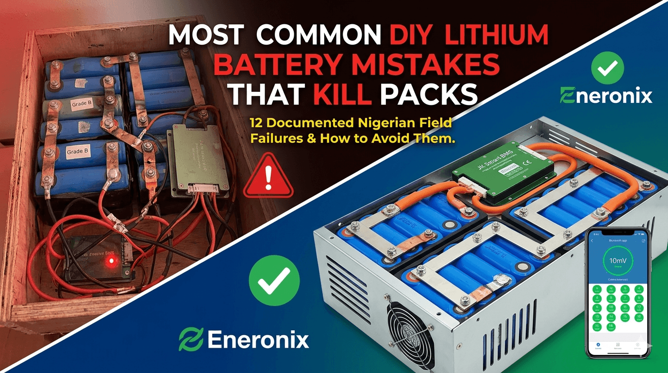
Most Common DIY Lithium Battery Mistakes
TL;DR
What this covers: 12 documented DIY LiFePO4 battery build and configuration mistakes from Nigerian field installations, with root causes and fixes. Who it is for: anyone building or commissioning a DIY LiFePO4 battery pack for solar storage. Key takeaways: Most packs fail because of build process errors, not bad cells. The cells are often fine. The mistakes that kill packs fastest are skipping capacity testing, no top balance, and passive-only BMS balancing. Many of these mistakes are invisible for 6 to 12 months before symptoms appear. Every single one is preventable with knowledge and process. Estimated read time: 16 to 20 minutes.
I have seen a lot of DIY LiFePO4 battery packs. Beautifully built packs that lasted 10 years. Expensive packs that started declining within 8 months. Packs made from cells that tested perfectly at 200Ah each, delivering 120Ah after 18 months of daily cycling. Packs made from cells that tested at 192Ah each, still delivering 185Ah at cycle 1,500.
The difference is almost never the cells. The cells are usually fine. The difference is almost always the build process, the BMS specification, the configuration, and the thermal environment. Get those right and Grade A LiFePO4 cells will outlast the inverter, the roof, and possibly the building. Get them wrong and you will be explaining to a customer why their expensive battery system needs partial replacement before the first anniversary.
This article documents the twelve mistakes I see most frequently in Nigerian DIY battery builds, in order from the ones that do immediate damage to the ones that accumulate slowly over months. Each mistake has the engineering reason it causes damage, how it manifests in the field, when you will notice it, and exactly what to do instead. Every one of these is preventable. None requires expensive tools or special expertise. They all just require following a process.
This article is the capstone of the Phase 3 DIY battery build series. For the detailed procedures behind any of the fixes referenced here, every step is covered in the linked articles throughout.
The Twelve Mistakes at a Glance
Use this as a build checklist. Before each installation, go through this table and confirm that none of these conditions apply.
| # | Mistake | When It Bites | Long-Term Consequence |
| 1 | Using Grade B or ungraded cells | Day 1 | Imbalance and premature capacity loss from month 3 onward |
| 2 | Skipping capacity testing | Day 1 | Hidden capacity mismatch compounds into visible divergence by month 6 |
| 3 | Skipping top balance before assembly | Day 1 | First charge cycle already imbalanced; pack never achieves designed capacity |
| 4 | Wrong BMS cell count (S rating mismatch) | Day 1 | Immediate BMS malfunction or unmonitored cells from first power-up |
| 5 | Connecting B+ before all tap wires verified | Day 1 | Immediate permanent BMS IC damage in many cases |
| 6 | Undersized BMS current rating | Ongoing | Progressive MOSFET degradation; BMS failure at 12 to 18 months |
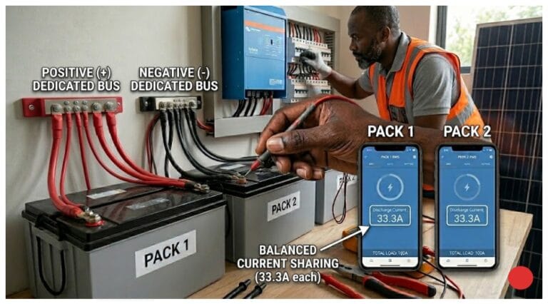
| 7 | No RS485/CAN communication to inverter | Ongoing | Inverter uses voltage-based SOC; 15 to 25% SOC error; premature generator use |
| 8 | Factory default BMS thresholds left unconfigured | Ongoing | Suboptimal protection for specific cells and Nigerian conditions |
| 9 | Undersized busbars and cables | Ongoing | Voltage drop errors; false UVP trips; potential overheating |
| 10 | No pre-charge circuit | Every startup | MOSFET degradation from inrush; OCP trips; BMS failure at 18 months |
| 11 | Poor enclosure ventilation | Ongoing (seasonal) | Accelerated aging in hot dry season; OTP trips; 30 to 50% shorter cell lifespan |
| 12 | No annual health check | Year 2 onward | Developing problems go undetected until customer calls |
| KEY TAKEAWAY | The mistakes in rows 1 through 5 happen before the first charge cycle. The mistakes in rows 6 through 11 develop over months. The mistake in row 12 is what turns a small developing problem into a major one. Address all twelve. |
Mistake 1: Using Grade B Cells to Save Money
Grade B LiFePO4 cells are typically 20 to 40% cheaper than Grade A from the same supplier. The cost saving is real and the cells work, which makes this a tempting decision. The problem is what Grade B actually means.
Grade B cells are cells that did not pass the manufacturer’s Grade A specifications during factory quality control. They were rejected for one or more of the following: capacity below the rated minimum, internal resistance above the rated maximum, higher-than-acceptable self-discharge rate, or surface or electrode defects discovered during formation cycling. The exact reason any individual Grade B cell was rejected is not communicated to you when you buy it.
In a series string of 16 cells, a single Grade B cell with 15% lower capacity than its neighbours diverges from the string within the first 100 cycles. It hits OVP first during charging and UVP first during discharge. The BMS active balancer fights it every cycle. By cycle 300, the cell has been pushed to voltage extremes repeatedly and its capacity has declined further from the cycling stress. By cycle 500, it is delivering 60 to 70% of the capacity of the other cells and limiting the accessible range of the entire 16S pack.
The full mechanism of how a single weak cell limits an entire pack is documented in our article on why lithium batteries go out of balance. The Grade B scenario is a more aggressive version of the normal cell divergence process.
The fix is straightforward: use Grade A cells from a reputable supplier, test each cell’s actual capacity before assembly, and discard or return any cell that falls outside 2% of the batch median. The money saved on Grade B cells over the life of a daily-cycling solar pack is a poor trade against the capacity loss and service complexity that follows.
Mistake 2: Skipping Capacity Testing
Even Grade A cells from a reputable supplier vary in actual capacity. A 200Ah rated cell may genuinely measure anywhere from 196Ah to 204Ah. In a string where most cells are at 200Ah and one is at 188Ah, that one cell fills 6% faster and empties 6% faster on every single cycle.
After 200 cycles, the 12Ah gap between that cell and its neighbours has been expressed as a voltage divergence 200 times. The BMS active balancer has been working against it since day one. The cell is experiencing slightly more stress per cycle than its neighbours. Its capacity degrades slightly faster. By cycle 500, what started as a 12Ah mismatch may have grown to 18Ah as the weaker cell ages faster under the stress.
Capacity testing takes 8 to 10 hours per cell at 0.2C discharge rate. With four capacity testers running in parallel, you can test all 16 cells for a 16S pack in two days. The procedure is: charge each cell individually to 3.65V at 0.2C, rest for 30 minutes, discharge at 0.2C to 2.50V, measure total Ah delivered. Any cell more than 2% below the batch median does not go in the pack.
The complete capacity testing procedure with each step explained is in our Phase 3 Article 1: how to build a LiFePO4 battery pack step-by-step. The testing section specifically explains why 0.2C is the correct rate and what to do with cells that test out of spec.
Mistake 3: Assembling Without Top Balancing
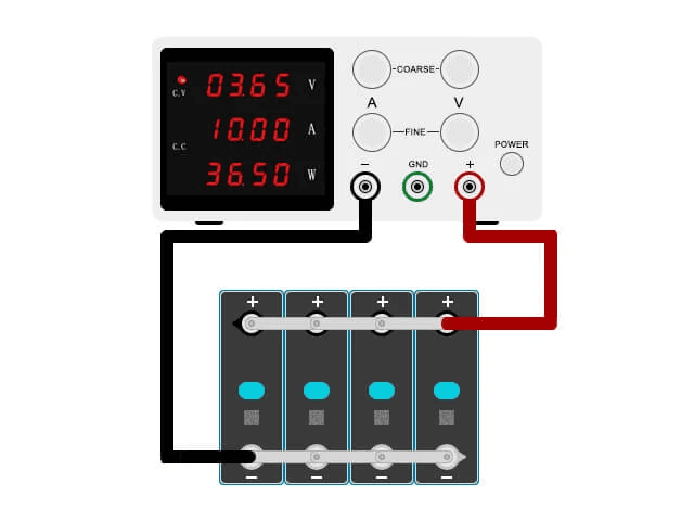
Top balancing is a 6 to 8 hour parallel charge procedure that brings all cells to the same state of charge before series assembly. Most builders skip it because the pack appears to work fine without it for the first few weeks.
Here is what actually happens without it. Cells arrive from capacity testing at approximately 2.50V. You store them for two days while finishing the enclosure. Self-discharge varies between cells. By the time you assemble, the cells range from 3.18V to 3.35V across the 16-cell batch. You connect them in series. The BMS starts charging. The cells at 3.35V hit OVP in the first 20 minutes. The BMS trips. You reset and continue. The cells at 3.18V have barely moved.
The first charge cycle has already established an imbalance pattern. Cell 4 is chronically ahead. Cell 11 is chronically behind. The active balancer spends the rest of the pack’s life managing a deficit it never had to manage if you had top balanced properly.
The full top balance procedure, including why you hold at CV until current drops below 0.25A and not just until current drops to 5A, is in our article: top balancing vs bottom balancing: what every DIY builder gets wrong.
| KEY TAKEAWAY | Top balancing takes 6 to 8 hours. Do it the night before assembly. Set the power supply to 3.65V, current limit to 0.1C, and leave it running. Come back in the morning, verify all cells read 3.62 to 3.65V, and assemble immediately. The entire process requires 15 minutes of active effort. |
Mistake 4: Wrong BMS Cell Count
A 16S LiFePO4 pack needs a 16S BMS. Not a BMS labelled 48V. Not a BMS labelled ‘large’. A BMS with exactly 16 series cell monitoring channels.
The most common version of this mistake is using a 16S BMS for a 15S pack (usually because a cell was damaged during assembly and the builder connected across it). The 16th channel has no cell to monitor. The BMS reads it as 0V and immediately trips UVP. Some builders interpret this as a faulty BMS and return it. The BMS was working correctly.
The other version is using an 8S BMS (labelled as a 24V BMS) for a 16S pack because it was available and cheap. The first 8 cells are monitored. The remaining 8 are completely unprotected. The pack appears to work. The unmonitored cells can be overcharged, deep-discharged, or develop imbalance with no protection responding. This is a safety and performance problem simultaneously.
The relationship between S rating, pack voltage, and BMS cell count requirement is explained in detail in our article: 4S, 8S, 16S LiFePO4 battery configuration. Always verify the BMS S rating from the datasheet, not from the voltage label on the packaging.
Mistake 5: Connecting B+ Before Verifying Tap Wire Order
This is the fastest way to turn a 25,000 naira JK BMS into scrap. The cell tap wires must all be correctly connected before B+ is powered up. The BMS cell monitoring IC reads all cell voltage channels simultaneously on power-up. A tap wire in the wrong position presents a voltage many times above the IC’s rated input to one of its measurement channels. The IC is destroyed in microseconds.
The correct sequence is: connect all tap wires in order from B0 to B16, verify each against the wiring diagram, connect B-, then connect B+. Verify all 16 cell voltages in the BMS app immediately after connecting B+. If any cell reads 0V, maximum voltage, or a static wrong value, disconnect B+ immediately and recheck that channel.
The full power-up sequence with the engineering explanation for why each step must happen in this specific order is in our article: how to wire a BMS correctly without destroying it. Read it before touching the BMS on any new build.
Mistake 6: Undersized BMS Current Rating
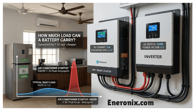
A BMS rated at 100A on a 5kVA 48V system will fail. Not immediately. Not dramatically. It will fail progressively over 12 to 18 months as the MOSFET switches degrade from sustained thermal stress.
The calculation: a 5kVA inverter at 48V draws approximately 109A at full load. The BMS must handle 109A continuously. The minimum BMS rating for Nigerian conditions is 109A x 1.25 (standard margin) x 1.15 (Nigerian thermal derating) = 156A. The next standard size is 200A. Using a 100A BMS is 60% underpowered for the application.
The symptom that appears at month 14 is a BMS that trips OCP under loads that never caused a trip before. The MOSFET on-resistance has increased enough that normal current registers as overcurrent. The installer thinks the BMS threshold drifted or the cells weakened. Neither is true. The MOSFETs have degraded from 14 months of running above their thermal design point.
The complete BMS current sizing calculation including the Nigerian thermal derating factor and the worked example for a 5kVA system is in our article: how to size a BMS correctly. The four-step formula takes 5 minutes to apply and eliminates this class of failure entirely.
Mistake 7: No BMS-to-Inverter Communication
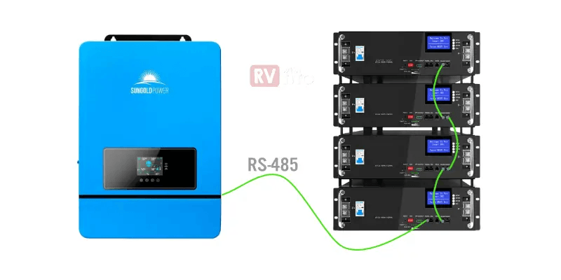
The RS485 cable is physically present. It is coiled neatly next to the BMS and the inverter, disconnected at both ends, because nobody configured it and nobody thought it mattered.
Without BMS communication, the inverter estimates battery SOC from terminal voltage. For LiFePO4, the voltage curve is flat between 20% and 90% SOC, varying by only 50 to 100mV across that entire range. The inverter guesses wrong by 15 to 25% consistently. It switches to generator backup when the battery has 30% remaining. It terminates charging before the battery is actually full.
Over two years of daily cycling with a 20% SOC error, the battery is chronically undercharged and over-discharged relative to its actual state. The cells cycle in a range they were not designed for. Capacity loss accelerates. Generator fuel cost increases. The customer’s electricity bills go up and their battery degrades faster simultaneously.
The quantitative cost of operating a LiFePO4 system without BMS communication is documented in our article: SOC drift: why your BMS and inverter disagree. The generator fuel numbers alone make the case for the 30 minutes it takes to connect and configure the RS485 cable.
| KEY TAKEAWAY | Connect the RS485 cable. Configure the inverter battery type. Verify SOC shows as a percentage in the inverter display. This takes 30 minutes and changes the system from one that guesses to one that knows. |
Mistake 8: Leaving BMS Thresholds at Factory Defaults
A JK BMS ships with protection thresholds set for a global average user. OVP might be 3.70V when you need 3.65V. UVP might be 2.50V when you should be at 2.80V for daily cycling health. The charge OTP might be 60 degC when a Lagos generator room demands 50 degC. Balance start threshold might be 50mV when 10mV would catch imbalance earlier.
None of these defaults produce catastrophic immediate failures. They produce a system that is slightly suboptimal in every parameter simultaneously: charging cells 50mV above their optimal endpoint, discharging them 300mV below the conservative daily cycling cutoff, allowing balancing to start later than it should, and permitting charging at temperatures that accelerate electrolyte decomposition in Nigerian summer conditions.
The fix takes 5 minutes in the JK BMS app: OVP to 3.65V, UVP to 2.80V, charge OTP hard cutoff to 50 degC, balance start threshold to 10mV, balance current to 2A, RS485 baud rate to 9600. Do this before the first charge cycle, not after it.
The specific dangers of each default threshold and why Nigerian conditions require more conservative settings than global defaults is covered in our article: 6 dangers of setting BMS cutoffs from cell datasheets alone.
Mistake 9: Undersized Busbars and Cables
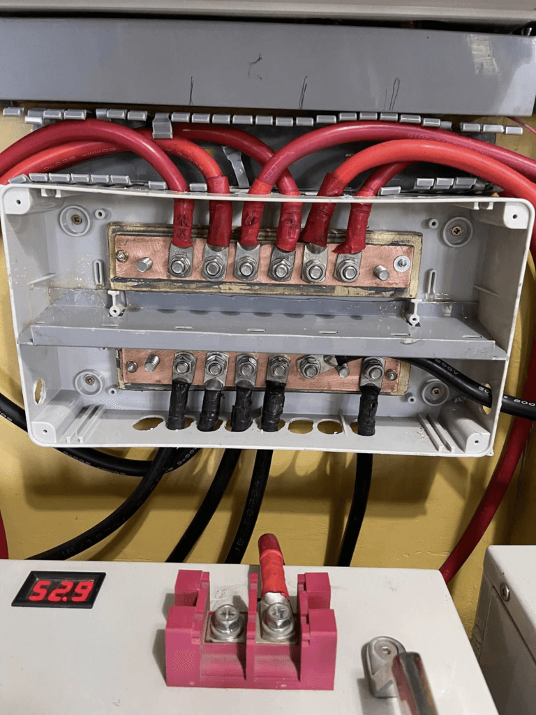
You will not notice an undersized cable by looking at it. Both a 25mm2 cable and a 50mm2 cable look like reasonable copper wire in a battery enclosure. The difference shows up in the BMS app as premature UVP trips under high-current loads.
The mechanism: at 150A through a 25mm2 cable that is 1.5 metres long, voltage drop is 150 x (1.72e-8 x 1.5 / 25e-6) = 0.154V. The BMS is reading cell voltages that are 0.154V lower than the cells actually are. A cell genuinely at 2.95V reads as 2.796V to the BMS. The BMS trips UVP. The cells still have 15% of their capacity remaining.
The customer reports that the battery cuts out too early. The cells are tested and found to be perfectly healthy. The cable was the problem the whole time, and it has been the problem since day one without anyone noticing because the BMS trips looked like low battery events rather than wiring issues.
The complete cable sizing calculation framework, including the 0.5V total voltage drop budget and the worked example for a 5kVA system, is in our article: busbar sizing, cable sizing, and fuse selection. The formula is one line of arithmetic and should be applied before buying any cable.
Mistake 10: No Pre-Charge Circuit
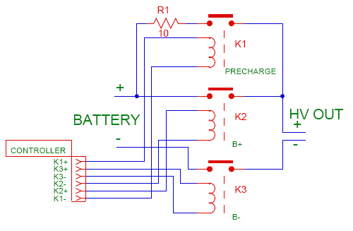
Every time you start the inverter without a pre-charge circuit, 300 to 800 amps flow through the BMS MOSFET switches for 10 to 20 milliseconds as the inverter’s capacitor bank charges from zero to pack voltage. The BMS OCP protection may or may not trip. Either way, the MOSFET junction absorbs the thermal spike.
One startup event does not destroy a good MOSFET. Two hundred startup events over 18 months of daily operation cause cumulative semiconductor lattice damage that progressively increases MOSFET on-resistance. At month 18, what used to be a 150A BMS is now effectively a 120A BMS from resistance increase. At month 22, OCP trips under normal evening loads. At month 24, the BMS requires replacement.
A pre-charge circuit: 10-ohm wirewound resistor, time-delay relay set to 500ms, total cost under 3,000 NGN. It limits inrush to 6A. The MOSFET sees no surge. The BMS lasts its full designed service life.
The physics of inverter capacitor inrush, the MOSFET degradation mechanism, and the complete pre-charge circuit design are in our article: why your inverter sparks when you connect the battery. The article includes calculations for every common inverter size and the component list for the pre-charge circuit.
Mistake 11: Inadequate Enclosure Ventilation
LiFePO4 cell aging is thermally activated. At 40 degC average cell temperature during cycling, a cell ages at approximately twice the rate it does at 30 degC. At 50 degC, four times the rate. According to the Arrhenius equation for lithium battery aging (published in extensive detail in research from the National Renewable Energy Laboratory and in lithium cell manufacturer application notes from CATL and EVE Energy), every 10 degC increase in average operating temperature roughly doubles the rate of capacity fade.
In a generator room during the dry season, an unventilated battery enclosure reaches 48 to 55 degC during peak afternoon charging. A pack that would last 10 years at 30 degC lasts 2.5 to 4 years at 50 degC. This is not a theoretical risk. It is the most common cause of battery packs that fail to achieve even half their designed cycle life in Nigerian installations.
The fix is enclosure design: route airflow across the cells from bottom to top, ensure at least 25mm clearance between cells and enclosure walls, add a small thermostat-controlled DC fan that activates above 35 degC. The BMS charge OTP at 50 degC provides the backstop protection, but the goal is to keep the pack cool enough that OTP rarely fires.
| THE NUMBER THAT MATTERS | Target a maximum cell temperature of 40 degC during peak charging. Not 50 degC. Not 45 degC. 40 degC. At 40 degC, the aging rate is manageable for a 10-year design life. At 50 degC, you are delivering a 4-year pack while charging the customer for a 10-year one. Good ventilation design is the cheapest way to add 6 years to a battery system’s useful life. |
The thermal aging mechanism and the practical ventilation strategies that keep pack temperatures below 40 degC in Nigerian conditions are covered in our article: how to increase lithium battery lifespan. The article includes specific enclosure design guidance for generator rooms in hot climates.
Mistake 12: No Annual Health Check
A battery pack installed and never inspected is a pack that accumulates small problems until they become large ones. The OTP that fires three times a week because the ventilation fan failed six months ago. The cell whose voltage spread has grown from 20mV to 140mV because the active balancer developed a fault. The RS485 cable that worked loose from the inverter terminal and has been providing no communication for four months while the inverter guesses SOC from voltage.
None of these announce themselves. The customer does not call because the system still appears to work. The power still comes on. The loads still run. But the battery is degrading faster than designed and the protection is running incomplete.
An annual health check takes 20 minutes:
- Open BMS app. Read cell voltage spread during CV phase. Under 30mV is healthy. Over 100mV needs investigation.
- Check BMS fault log. Any OTP trips? Any OCP trips? More than 2 to 3 per month suggests an environmental or sizing problem.
- Verify inverter SOC display shows percentage and matches BMS app within 5%. If not, check the RS485 connection.
- Measure MOSFET temperature under load with IR thermometer. Above 55 degC during normal load needs attention.
- Inspect all busbar and cable connections visually. Any discolouration around terminals indicates heating from poor contact. Retorque and clean.
Twenty minutes once per year to catch problems before they compound. The alternative is a site visit and a difficult conversation with a customer who wants to know why their 400,000 naira battery system needs expensive repairs in year two.
The full diagnostic procedure including what each BMS app reading means and how to interpret anomalies is in our article: signs of a failing BMS. The 10-step protocol in that article covers every check that matters for annual maintenance.
The Pattern Behind All Twelve Mistakes
Reading through this list, a pattern becomes clear. Most of these mistakes happen because the builder was trying to save time, save money, or avoid complexity. Grade B cells save money. Skipping capacity testing saves two days. Not configuring the BMS saves 5 minutes. Not installing pre-charge saves 3,000 naira. No ventilation fan saves 2,000 naira and some wiring work.
The savings are real and immediate. The consequences are deferred, compounding, and much larger than the savings.
A correctly built 16S 200Ah LiFePO4 pack using Grade A cells, a well-configured active BMS, proper communication, correct cable sizing, a pre-charge circuit, and an adequately ventilated enclosure is a system that a customer will still be running effectively at cycle 2,000. That is roughly 5 to 6 years of daily cycling.
An incorrectly built version of the same pack, with three or four of the twelve mistakes made, typically reaches 80% capacity loss within 18 months. Not because lithium iron phosphate is a bad chemistry. It is actually excellent. Because the build process treated a high-performance electrochemical system as if it were a car battery you just bolt in.
Do the work properly. Test the cells. Top balance before assembly. Size the BMS correctly. Connect the communication cable. Configure the thresholds. Add the pre-charge circuit. Ventilate the enclosure. Check it annually. Every one of those actions pays back more than it costs, measured in battery lifespan, customer satisfaction, and your own reputation as someone who builds systems that actually work.
| KEY TAKEAWAY | Twelve mistakes. Every single one is preventable. The cells are rarely the problem. The build process is almost always the problem. Fix the process. |
Frequently Asked Questions
What is the most common reason DIY lithium battery packs fail early?
From field observations across Nigerian solar installations, the most common root cause of premature DIY pack failure is a combination of skipping capacity testing and using passive-only BMS balancing. Cells with undetected capacity mismatches of 3 to 8% are assembled into packs and immediately begin diverging. Without active balancing to correct the divergence each cycle, the spread compounds to 150 to 300mV within 18 months and the pack is delivering 65 to 75% of its original capacity. The customer assumes the cells have failed. The cells are mostly fine. The build process was incomplete.
How do I know if my DIY battery pack is performing correctly?
Three checks give you a clear picture. First, open the BMS Bluetooth app during the CV charge phase and read the cell voltage spread. Under 30mV is healthy with active balancing. Above 100mV means imbalance is developing. Second, cross-reference the BMS app SOC against the inverter display SOC. They should agree within 5%. A large difference means either the communication link has failed or the current sensor has drifted. Third, time how long the system runs at a known load compared to commissioning. A 15% or greater reduction in runtime at the same load in under 18 months indicates a performance problem that needs investigation.
Is it safe to use Grade B LiFePO4 cells in a solar storage pack?
Grade B cells are acceptable for low-stakes applications with infrequent cycling, where the lower cost justifies accepting the higher defect rate and wider capacity spread. For a daily-cycling solar storage pack that you expect to last 5 to 10 years and represent a significant investment, Grade B cells are not a cost saving. They produce higher initial imbalance, diverge faster over cycles, and require more active balancing just to stay at the performance level a Grade A pack starts at. The cost difference between Grade A and Grade B cells for a 16S 200Ah pack is typically 15,000 to 30,000 NGN. The performance difference over 3 years is several hundred thousand naira in capacity retention.
What happens if I use the wrong inverter settings with a LiFePO4 battery?
The two most damaging wrong inverter settings are: using lead-acid charge voltage settings (typically 56 to 57.6V for 48V systems) instead of lithium settings (58.4V for 16S LiFePO4), and not setting up BMS communication so the inverter uses voltage-based SOC estimation. Lead-acid settings chronically undercharge the pack, leaving it at 90 to 95% of full charge on every cycle. Over time this causes lithium site immobilisation in the cathode that permanently reduces accessible capacity. Voltage-based SOC causes generator to run unnecessarily early and may allow the pack to be over-discharged if the inverter’s low-battery cutoff is set too aggressively.
Can I fix a DIY battery pack that was built incorrectly?
It depends on when and what. If the pack has been running for under 3 months and the cells are not significantly degraded, many build errors are recoverable. A pack assembled without top balance can be disassembled, top balanced, and reassembled. A BMS with wrong thresholds can be reconfigured. Undersized cables can be replaced.
A missing pre-charge circuit can be added. If the pack has been running for 12 to 18 months with significant imbalance, some cell degradation has already occurred. Correct the build errors, run a full top balance, reconfigure the BMS, and monitor performance over the next 30 days. If capacity does not recover to 85% or better after correction, individual cell testing is needed to identify which cells have degraded beyond recovery.
How long should a correctly built DIY LiFePO4 battery pack last?
A correctly built pack using Grade A LiFePO4 cells, a correctly sized and configured smart BMS with active balancing, proper communication with the inverter, adequate ventilation, and conservative cycling parameters (80% DoD maximum) should achieve 3,000 to 5,000 charge cycles before capacity drops to 80% of original. At one cycle per day, that is 8 to 14 years of service life. Incorrectly built packs with passive balancing, communication failures, or thermal mismanagement commonly show 80% capacity loss within 18 months to 3 years of daily cycling.
What is the single most important thing to do before commissioning a new DIY battery pack?
Configure the BMS thresholds in the app and verify inverter communication before the first charge cycle. A JK BMS running on factory defaults is not correctly configured for Nigerian conditions or for your specific cells. Set OVP to 3.65V, UVP to 2.80V, charge OTP to 50 degC, balance start threshold to 10mV, balance current to 2A. Then connect the RS485 cable and verify the inverter shows SOC as a percentage rather than a voltage. Five minutes of configuration work before the first charge determines whether the system is optimised from day one or whether it spends its entire life operating on defaults that do not match the installation.
External References (Also Cited in Article Body)
- NREL — Lithium battery capacity fade: thermal acceleration and Arrhenius analysis for stationary storage applications
- CATL — LFP200 cell application notes: recommended operating temperature range and thermal derating
- EVE Energy — LF280K cell specification and temperature-dependent aging characterisation
- JEDEC — JESD22-A108: Temperature cycling effects on semiconductor devices including MOSFET degradation
- IEC 62619 — Safety requirements for secondary lithium cells and batteries in industrial applications

I am Engr. Ubokobong Ekpenyong, a solar specialist and lithium battery systems engineer with over five years of hands-on experience designing, assembling, and commissioning off-grid solar and energy storage systems. My work focuses on lithium battery pack architecture, BMS configuration, and system reliability in off-grid and high-demand environments.