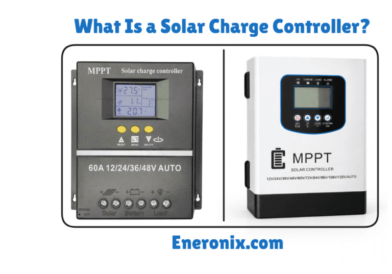
How Does a Solar Charge Controller Work?
Every solar panel produces more voltage than a battery can safely accept.
A typical “12V” solar panel operates at around 17–18V under load and can exceed 20V in full sun. Larger residential panels often run at 30–40V or more. Meanwhile, the battery they’re charging may only need 14.4V. Without something controlling that difference, the battery receives more voltage than it was designed to handle.
The damage doesn’t happen instantly. Lead-acid batteries slowly lose electrolyte, plates corrode, and capacity falls month after month. Lithium batteries can suffer permanent cell degradation from repeated overvoltage events. By the time the problem becomes obvious, the battery bank is often already damaged.
The component that prevents all of this is the solar charge controller.
But “prevents overcharging” is only part of the story.
Modern charge controllers are continuously measuring voltage, current, temperature, and battery state, then making hundreds of switching decisions every second to regulate how energy flows from the solar array into the battery. PWM controllers do this one way. MPPT controllers do it another. Both are solving the same problem: converting a constantly changing solar power source into a charging profile the battery can safely accept.
Understanding how that process works matters whether you’re designing a new solar system, troubleshooting poor battery performance, comparing PWM and MPPT controllers, or trying to determine why a battery bank is failing earlier than expected.
In this guide, we’ll look inside the charge controller itself: how voltage regulation works, how PWM and MPPT algorithms control power flow, what happens during bulk, absorption, and float charging, how temperature compensation affects battery life, and what occurs when regulation fails.
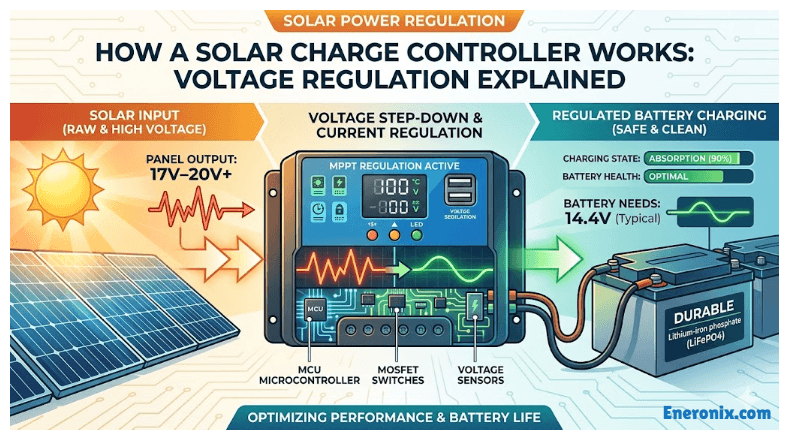
What “Regulation” Really Means
Here’s something that catches people off guard. That solar panel that is labelled 12V, doesn’t output 12V. Under full sun with nothing connected, it outputs somewhere between 20V and 22V. At its maximum power point, it’s operating around 17 to 18V. The “12V” label is a system classification, a way of telling you which battery bank and controller it’s designed to pair with. It is not a voltage reading.
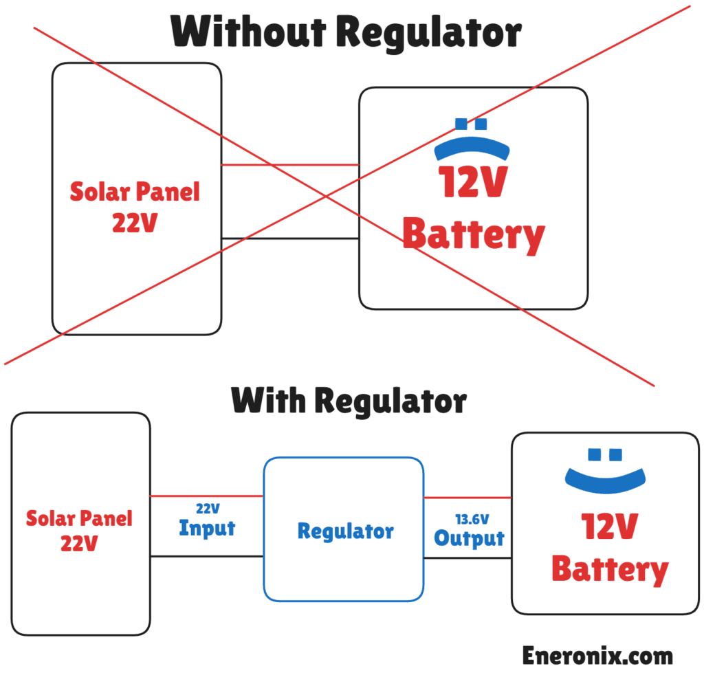
This matters because of how charging works. To push current into a battery, the source voltage has to be higher than the battery voltage. A 12V lead-acid battery in a healthy state sits around 12.6V resting. To charge it properly, you need to push it up to 14.4V during bulk and hold it at 13.6V in float. The solar panel needs headroom above those targets to drive current in. That headroom is exactly what Vmp provides.
Now look at a 24V system. A nominal 24V PV, has a Vmp around 35 to 36V and a Voc that can reach 44 to 46V. Your 24V lead-acid battery bank charges at 28.8V bulk. The gap between what the solar panel produces and what the battery needs is a big one, and that gap is where all the damage happens if there’s nothing actively managing it.
For LiFePO4, the tolerance is tighter. A 12V LiFePO4 pack charges to a maximum of 14.2V to 14.6V depending on the manufacturer. Push it past that ceiling, even briefly, and you start forcing excess lithium ions into the cathode material. The result is lithium plating on the anode, which is permanent. Those cells don’t recover. You can read more about what happens to lithium cells under overvoltage conditions in the LiFePO4 battery architecture guide.
“Regulation” means the controller is monitoring battery voltage continuously and adjusting current flow in real time to stay within these windows. Not once a second. On quality controllers, sensor sampling and switching decisions happen hundreds of times per second. The battery is always being watched.
Think of it less like a switch and more like a throttle. When the battery is low, the throttle is wide open and maximum available current flows in. As the battery fills and voltage climbs toward the setpoint, the throttle eases back. When it hits the target, the controller shifts into maintenance mode. That active, continuous adjustment is what regulation actually means.
Inside The Charge Controller
Most people treat a charge controller as a box. Voltage goes in, regulated power comes out. That mental model works fine until something fails or you’re trying to explain to a client why a ₦15,000 no-name unit isn’t the same thing as a Victron SmartSolar. That difference is almost entirely in this hardware stack.
Voltage sensors
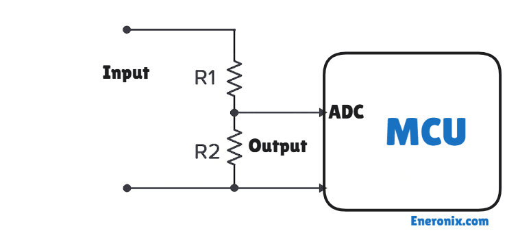
The controller is monitoring two voltage points simultaneously: the PV input side and the battery output side. Both are sampled continuously, typically using resistive voltage divider circuits feeding into the MCU’s analog-to-digital converter. On quality controllers, this happens at millisecond intervals. Every charging decision the controller makes traces back to these two readings. If either sensor is inaccurate or drifts with temperature, every downstream decision is wrong.
Current sensors
There are two main approaches: shunt resistors and Hall-effect sensors. A shunt resistor is a precision low-resistance element placed in the current path; the voltage drop across it is proportional to current. Hall-effect sensors measure the magnetic field generated by current flowing through a conductor, without direct electrical contact. MPPT controllers track both input current from the panels and output current to the battery separately, because they need to compute real-time power on both sides. Power is voltage multiplied by current, and the MPPT algorithm is continuously recalculating that figure to find the panel’s maximum output point.
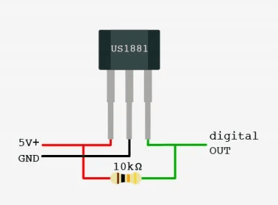
Temperature sensor
This is the component most installers never think about, and in Nigerian conditions it’s arguably the most important one after the voltage sensors. Lead-acid batteries require charge voltage to be reduced as temperature rises. The standard compensation coefficient is -3mV per cell per degree Celsius above the 25°C reference. On a 12V lead-acid battery with six cells, that’s -18mV per degree.
At 40°C ambient, which is a typical dry-season afternoon in Lagos, the bulk voltage should be reduced by about 0.27V from the 25°C setpoint. At 50°C inside a sealed enclosure, the reduction should be closer to 0.45V. A controller charging at a fixed 14.4V bulk in those conditions is continuously overcharging, quietly accelerating electrolyte loss and plate corrosion with every sunny day.
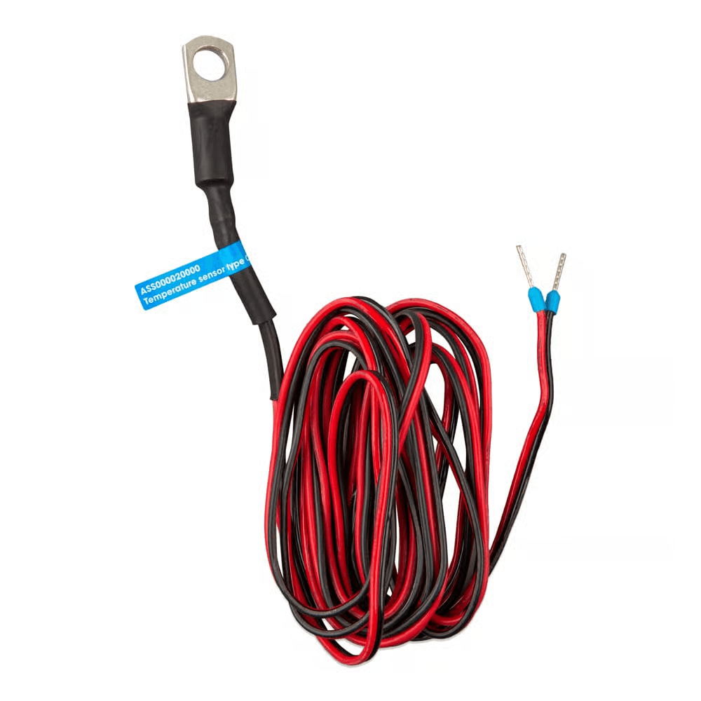
The sensor itself is either mounted internally on the controller board, measuring ambient air temperature, or connected externally via a probe attached directly to the battery surface. External probe is the correct setup for any quality installation. An internal sensor measures the controller’s environment, not the battery’s. In a system where the battery and controller are in different locations, those temperatures can differ by 10°C or more.
The microcontroller unit
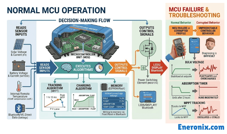
This is the decision-making core. It reads all sensor inputs, runs the charging algorithm, and outputs control signals to the power switching element. On MPPT controllers, it also executes the tracking algorithm, typically every 1 to 10 milliseconds. It stores your programmed setpoints: bulk voltage, float voltage, absorption timer, temperature compensation coefficient. When you change settings on the front panel or via Bluetooth on a Victron unit, you’re writing to the MCU’s memory. When the MCU fails or runs a corrupted profile, the controller’s behaviour becomes unpredictable in ways that are very difficult to diagnose without a calibrated multimeter and some patience.
The power MOSFET
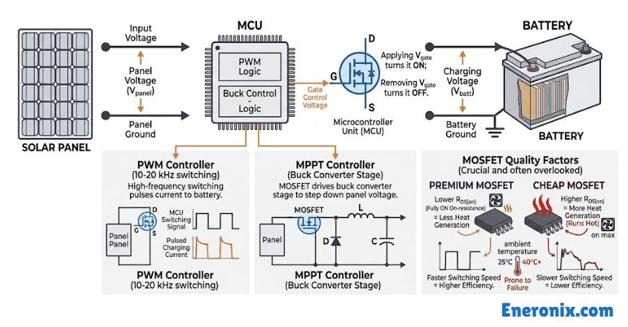
The MOSFET is the physical gating element between the panel and the battery. It’s a transistor controlled by gate voltage from the MCU. Applying voltage to the gate turns it on; removing it turns it off. In a PWM controller, the MCU switches this gate on and off at high frequency, typically 10 to 20 kHz, to pulse current. In an MPPT controller, the MOSFET drives a buck converter stage that steps down the panel voltage. The MOSFET’s quality matters more than most buyers realise. On-resistance when fully on determines heat generation. Switching speed determines efficiency. Cheap MOSFETs run hotter and fail faster, especially above 40°C ambient.
Reverse current protection
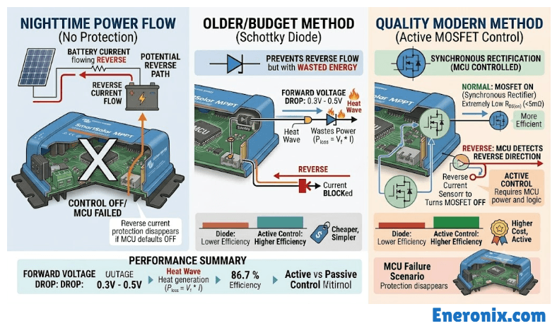
At night, with no panel output, there’s a potential path for battery current to flow backwards through the circuit into the panels. Older and budget controllers use a Schottky blocking diode to prevent this. It works but wastes energy as a forward voltage drop of 0.3 to 0.5V during normal operation. Quality modern controllers use the MOSFET itself as a synchronous rectifier instead: the MCU detects current direction and turns the MOSFET off when reverse flow is detected. More efficient, but it requires active control. If the MCU fails and defaults to off, reverse current protection disappears with it.
How PWM Regulation Works
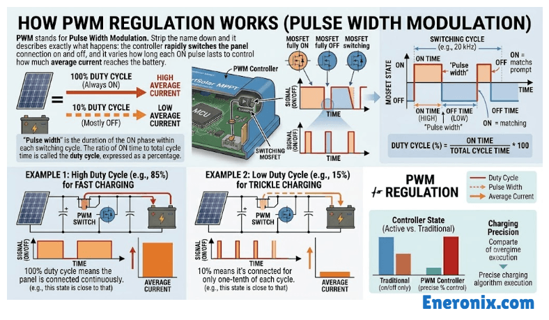
PWM stands for Pulse Width Modulation. Strip the name down and it describes exactly what happens: the controller rapidly switches the panel connection on and off, and it varies how long each ON pulse lasts to control how much average current reaches the battery.
“Pulse width” is the duration of the ON phase within each switching cycle. The ratio of ON time to total cycle time is called the duty cycle, expressed as a percentage. 100% duty cycle means the panel is connected continuously. 10% means it’s connected for only one-tenth of each cycle.
When the battery is deeply discharged, the controller runs at near-100% duty cycle. Full panel current flows in. As the battery charges and voltage climbs toward the bulk setpoint, the MCU starts reducing that duty cycle. Pulses get shorter. Average current tapers. By the time the battery reaches its absorption voltage target, the duty cycle has dropped to whatever level is needed to hold that voltage steady. At float, it drops further to just a trickle, enough to offset self-discharge.
That’s the mechanism. Simple, reliable, and genuinely effective when the system is sized correctly.
The problem is what happens to the voltage gap
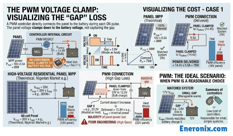
During each ON pulse, a PWM controller connects the panel directly to the battery. No conversion happens. The panel voltage physically clamps down to battery voltage at the moment of connection. If your panel is producing 18V at its maximum power point and the battery is sitting at 14.4V in bulk charge, the panel is pulled down to 14.4V the instant it connects. That 3.6V gap is not captured. It dissipates as heat in the MOSFET.
Now think about what that actually costs you. A panel rated at 18V Vmp and 5.5A produces 99W at its maximum power point. When a PWM controller clamps that panel to 14.4V, the current doesn’t increase to compensate. You’re delivering roughly 14.4V × 5.5A = 79W to the battery. About 20% of available power evaporated as heat. With a well-matched panel, that’s tolerable.
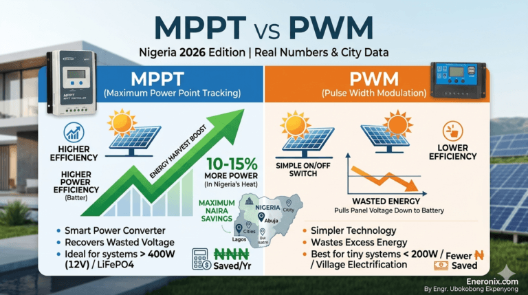
The situation gets worse as the voltage gap widens. A modern 60-cell residential panel common in the Nigerian market has a Vmp around 30 to 36V. Connect that through a PWM controller to a 12V battery bank and the controller clamps it from 33V down to 14.4V. You lose the majority of what the panel was capable of producing. This is not a malfunction. It is how PWM fundamentally works, and it is why using a PWM controller with higher-voltage panels is genuinely poor engineering, not just a minor inefficiency.
PWM works well in one specific scenario: when the panel’s Vmp closely matches the battery charge voltage, typically a 17 to 18V Vmp panel charging a 12V system. The gap is small, the waste is manageable, and the lower cost of PWM controllers makes them a reasonable choice for small, simple systems.
One thing worth knowing if you’re sourcing equipment in Nigeria: many controllers sold in Alaba and Computer Village as “PWM 30A” are implemented with a single switching transistor, a basic comparator circuit, and no meaningful switching frequency control. The switching frequency is one of the key quality indicators for a PWM unit, but it’s rarely printed on the label. A poor switching implementation runs hot, generates electrical noise on the battery, and has an early failure rate in high-ambient-temperature conditions. Cheap doesn’t necessarily mean simple. Sometimes it just means badly built. You can read more about the MPPT vs PWM trade-off for Nigerian installations specifically
How MPPT Regulation Works
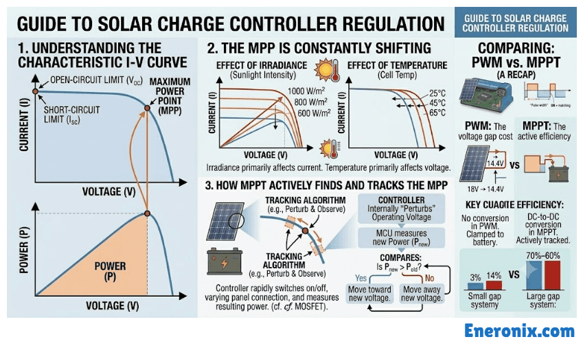
To understand MPPT, you first need to understand the I-V curve.
Every solar panel has a characteristic relationship between voltage and current at any given moment. Plot current on the vertical axis and voltage on the horizontal axis, and you get a curve that starts high on the left (high current, low voltage) and sweeps down to zero as voltage approaches the panel’s open-circuit limit. Somewhere on that curve is a single point where the product of voltage and current which is power is at its maximum. That point is the Maximum Power Point, and its exact position shifts constantly with temperature and irradiance.
On a hot Lagos rooftop in July, panel cell temperatures can reach 65 to 70°C. At that temperature, the panel’s maximum power point voltage can drop 10 to 15% below its rated STC value. The panel is producing less voltage than its nameplate suggests. In harmattan conditions with cooler ambient temperatures and stronger irradiance, the opposite happens. The MPP voltage rises. A controller that isn’t actively tracking this moving target is leaving power on the table every hour of every day.
The tracking algorithm
The most widely used algorithm is called Perturb and Observe, shortened to P&O. The name is exactly what it does. The controller makes a small deliberate change to the operating voltage a perturbation then measures whether power output went up or down. If power increased, it continues in that direction. If power decreased, it reverses. This repeats every few milliseconds, continuously nudging the operating point toward the peak.
P&O is simple, reliable, and effective under stable conditions. Its weakness appears when irradiance changes suddenly, as when a cloud passes. The controller perturbs the voltage in one direction, but the irradiance shift simultaneously moves the power curve. The algorithm can briefly interpret the irradiance change as the result of its own perturbation and step in the wrong direction. During that hunting period which typically lasts 1 to 3 seconds on a quality controller power harvest is briefly suboptimal.
Incremental Conductance is a more sophisticated approach. Rather than inferring direction from power change alone, it calculates the slope of the power-voltage curve mathematically. At the true maximum power point, the rate of change of power with respect to voltage equals zero. The algorithm compares incremental conductance to instantaneous conductance and determines not just which direction to move, but whether it has actually arrived at the peak and should stop oscillating. Under rapidly changing conditions, such as frequent cloud interruptions common during Lagos wet season, this produces more stable tracking. Both algorithms achieve 93 to 97% tracking efficiency in real-world conditions, with the gap between them widening only under frequently changing irradiance.
The buck converter stage
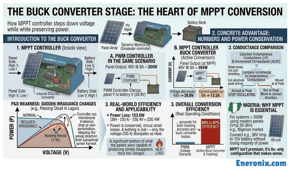
Once the algorithm has identified the maximum power point voltage, the controller faces a second problem. The panel is operating at, say, 48V to extract maximum power, but the battery needs 28.8V for a 24V system in bulk charge. Those two voltages need to be reconciled without wasting the difference as heat the way a PWM controller would.
This is where the buck converter comes in. A buck converter is a DC-to-DC step-down circuit. It takes higher voltage at lower current from the panel side and converts it to lower voltage at proportionally higher current on the battery side. The power is conserved in the conversion, minus small switching losses in the MOSFET and inductor.
The numbers make the advantage concrete. A 48V panel array producing 8A delivers 384W. The MPPT controller’s buck converter steps this down to 28.8V at approximately 13.3A for a 24V battery bank. The output is 383W. Almost nothing is lost only the voltage-to-current ratio has changed. Compare that to a PWM controller in the same scenario: it clamps the 48V array down to 28.8V during conduction, and the current doesn’t scale up to compensate. A significant portion of what the panels were capable of producing simply disappears.
Quality MPPT controllers achieve 93 to 97% overall conversion efficiency under real operating conditions. That figure accounts for both tracking accuracy and buck converter losses. For any system above 200W in Nigeria, particularly those using modern 60-cell panels with Vmp in the 30 to 36V range, MPPT isn’t a premium option. It’s the only configuration that actually makes sense. The MPPT charge controller selection guide covers how to size one correctly for your array.
How the Controller Executes The Charging Stage Sequence
The three-stage charging sequence bulk, absorption, float is usually described from the battery’s perspective. Here it’s worth looking at it from the controller’s side, because the controller is the one executing every transition. The battery is just responding.
Bulk stage
The controller opens the MOSFET fully, or in an MPPT unit, locks onto the panel’s maximum power point and holds it. Maximum available current flows into the battery. The battery voltage climbs steadily from wherever it started. The controller is watching that voltage continuously, every few milliseconds, waiting for one specific event: the moment battery voltage reaches the programmed bulk setpoint.
For a 12V lead-acid system that’s typically 14.4V. For 24V lead-acid, 28.8V. For a 12V LiFePO4 pack, the target is usually 14.2V to 14.6V depending on the cell specification. For 24V LiFePO4, 28.4V to 29.2V. The moment that threshold is crossed, the controller transitions. It doesn’t wait, doesn’t average, doesn’t apply a delay. The voltage hit the setpoint; bulk is done.
Roughly 70 to 80% of the battery’s total energy goes in during bulk. It’s the fastest phase because the battery’s internal resistance is low when depleted, and it accepts current readily.
Absorption stage
Now the controller switches from current-limited to voltage-regulated mode. Its job is to hold the battery voltage constant at the bulk setpoint. It does this by modulating the duty cycle of the MOSFET, backing off current just enough to prevent voltage from climbing further.
What happens inside the battery during absorption is electrochemically interesting. As the cells approach full charge, their internal resistance rises. Less current is needed to maintain the same terminal voltage. So current tapers naturally, not because the controller is directly reducing it, but because the battery itself is accepting less. The controller is just holding the voltage ceiling steady.
Absorption ends either on a timer commonly 1 to 2 hours on most programmable controllers or when current drops below a threshold, typically 2 to 5% of the battery’s Ah capacity. A 200Ah battery would transition out of absorption when charging current drops to 4 to 10A. Current-cutoff termination is more accurate than a fixed timer, but most budget controllers only offer time-based termination, and many set that timer too short. A battery that exits absorption at 85% state of charge because the timer ran out isn’t fully charged, regardless of what the controller display shows.
Float stage
The controller drops voltage to the float setpoint and holds it there indefinitely. For 12V lead-acid, that’s typically 13.6V. The small current flowing at float compensates for the battery’s natural self-discharge and keeps it sitting at full capacity.
For LiFePO4, this is where most installations get it wrong. LiFePO4 cells have extremely low self-discharge rates, and they don’t sulfate the way lead-acid does. They don’t need a continuous maintenance current. Holding a LiFePO4 pack at a float voltage of 13.6V keeps the top cells in a mildly stressed high-SOC state for hours every day. Over months, this causes SEI layer growth on the anode, sustained mechanical stress on cathode particles, and gradual lithium inventory loss.
The pack looks fine externally while quietly losing cycle life. A correctly configured controller on a LiFePO4 system should either disable float entirely or set it at the battery’s resting voltage, around 13.3V for a 12V pack, so no charging current actually flows. There’s a detailed breakdown of why this matters on why lithium batteries don’t need float charging
Equalization
This applies to flooded lead-acid only. Equalization is a periodic controlled overcharge, typically 15 to 15.5V on a 12V system, held for 2 to 4 hours. The purpose is to desulfate plates and redistribute electrolyte that has stratified in the cells. Done correctly and at the right interval, it extends flooded battery life meaningfully.
Never apply equalization to AGM, Gel, or any lithium chemistry. AGM and Gel batteries have no liquid electrolyte to redistribute, and the elevated voltage causes irreversible internal damage. On a significant number of cheap controllers sold in the Nigerian market, equalization is enabled by default and set to run automatically on a fixed schedule. Installers who don’t check this setting are routinely destroying AGM batteries without realising it. If you’re commissioning a system with AGM batteries, confirming equalization is disabled is not optional.
Temperature, Hot Climates, and What Most Controllers Get Wrong
Temperature compensation isn’t a bonus feature. In a country where ambient temperatures regularly hit 38 to 42°C and battery enclosures can exceed 50°C during dry season, it’s a core accuracy requirement. A controller without working temperature compensation is systematically overcharging your lead-acid batteries every single sunny day, and the damage accumulates invisibly until the batteries suddenly won’t hold charge.
Here’s the precise mechanism. Lead-acid battery chemistry becomes more reactive as temperature rises. The electrolyte conducts more freely, internal resistance drops, and the effective charge voltage threshold falls. The standard compensation coefficient is -3mV per cell per degree Celsius above the 25°C reference point. A 12V lead-acid battery has six cells, so the full-pack coefficient is -18mV per degree.
Work through the numbers for Lagos conditions. On a typical dry season afternoon with ambient at 40°C, the required correction is: (40 – 25) × 6 × 0.003 = 0.27V. Your bulk setpoint should drop from 14.4V to approximately 14.13V. At 50°C inside a sealed cabinet or BQ room during harmattan which is entirely realistic the correction becomes 0.45V, pushing the correct bulk voltage down to around 13.95V.
A controller running at a fixed 14.4V bulk in those conditions isn’t hitting a minor error. It is overcharging continuously, accelerating electrolyte gassing, boiling off water in flooded cells, accelerating grid corrosion in AGM types, and shortening battery life with every charge cycle. The battery doesn’t fail dramatically. It just slowly loses capacity and one day won’t hold a full charge anymore.
Some battery manufacturers actually recommend stopping charging entirely above 50°C. That threshold gets crossed routinely in sealed enclosures during peak dry season in Lagos.
The sensor placement problem
There are two ways a controller can measure temperature: an internal sensor on the controller’s own circuit board, or an external probe mounted directly on the battery surface. These can read very differently. A controller mounted in a ventilated location 1.5 metres from the battery bank in a separate cabinet may be reading 34°C while the battery surfaces are at 48°C. That 14-degree gap translates directly into a charging voltage error of about 0.25V, which is enough to cause chronic overcharge.
External temperature probe on the battery surface is the correct setup for any installation where accuracy matters. It’s not optional for lead-acid systems in hot climates. The probe attaches directly to the battery casing, typically secured with a cable tie, and feeds real battery temperature into the compensation algorithm.
What to watch for in the Nigerian market
Many controllers available locally have temperature compensation that is either absent, fixed at 25°C regardless of actual conditions, or listed in the spec sheet but implemented incorrectly. The only reliable way to verify it’s working is to measure bulk voltage with a calibrated multimeter at different ambient temperatures and confirm the output is shifting accordingly. Don’t rely on the controller’s own display.
For LiFePO4 systems, voltage temperature compensation is less critical because the chemistry is more tolerant across a temperature range. What matters instead is thermal protection: most quality controllers will halt charging above 45 to 50°C battery temperature. Cheap controllers often lack this protection entirely. At high temperatures, lithium cells degrade faster under charge, and a controller that keeps pushing current into a pack sitting at 55°C is doing real damage even if the voltage looks correct.
One practical point that applies to every installation regardless of battery chemistry: never mount a charge controller inside the same sealed enclosure as the battery bank. Batteries off-gas during charging. Charge controllers generate heat during operation. Combining both in an enclosed space accelerates failure on both ends. In Ajah, Satellite Town, and similar Lagos suburbs where systems are often installed in outdoor steel cabinets with no ventilation, internal temperatures routinely exceed what any controller is rated to handle. Ventilation and shade for the controller enclosure are not cosmetic considerations.
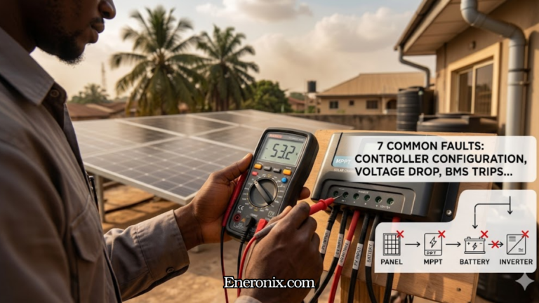
What Happens When Regulation Fails
Understanding the failure modes makes the whole regulation mechanism more concrete. Each one maps directly to a specific component or setting in the hardware stack described earlier.
Controller stuck in bulk overcharge failure
For LiFePO4, the BMS is the last line of defence. When cell voltage climbs above the overvoltage threshold, the BMS trips and disconnects the charge path. The system goes offline. If you’re getting repeated BMS disconnects on a sunny afternoon with no obvious load explanation, an overcharging controller is high on the list of causes. The more dangerous scenario is a cheap BMS that doesn’t trip correctly. In that case, lithium plating begins on the anode. That damage is permanent and invisible until capacity has already been lost. You can find a detailed breakdown of BMS protection thresholds and what happens when they’re breached in this BMS protection functions guide,
Float voltage set too high
This is one of the quietest and most common failure modes in Nigerian installations. An installer sets up a controller using a generic lead-acid profile on an AGM battery without adjusting the float voltage down from the default. The battery sits at 14.4V in float when it should be at 13.4 to 13.6V. No visible symptoms for weeks or even months. Then capacity suddenly drops and the battery won’t recover. By that point the damage is done.
The mechanism is straightforward: a float voltage that’s too high keeps a small but constant overcharge current flowing indefinitely. On AGM batteries, that current drives excess gassing through the recombination plates, accelerating their degradation. On flooded cells, it boils off electrolyte steadily. The battery looks fine on the controller display because voltage is where the controller expects it to be. The display is confirming the controller’s own output, not the battery’s actual health.
Missing or failed reverse current protection
At night with no panel output, current can flow backwards from the battery through the circuit into the panels. A failed blocking diode or a MOSFET-based protection circuit that isn’t activating correctly leaves this path open. Depending on array size, reverse current can reach 2 to 5A on a larger system.
The field symptom is a battery that drains overnight even with all loads disconnected. Many installers blame phantom loads, spend time checking the inverter and appliances, and miss the actual cause entirely. The diagnostic is simple: disconnect the PV input at the controller terminals overnight and check whether the battery holds its voltage. If it does, the reverse current path through the controller is the culprit. If it still drains, you’re looking at a genuine load issue. For a deeper look at phantom loads and standby draw in off-grid systems, our article on phantom loads and energy budgeting covers the full diagnostic process.
Wrong battery profile selected
A lead-acid charging profile applied to a LiFePO4 battery runs bulk voltage too high, float voltage too high, and likely enables equalization. None of these are immediately catastrophic because the BMS will trip on overvoltage before the worst damage occurs, but the repeated BMS disconnects stress the system and over time the mismatch degrades the pack. The reverse a LiFePO4 profile on a lead-acid battery sets bulk voltage too low and the battery never reaches full charge. After a few weeks the battery sits in a chronically undercharged state, sulfation begins on the plates, and capacity drops.
The field symptom for both scenarios is a battery that never seems to reach full charge, or one that’s consistently warm after a full day of sun with no heavy loads running. Neither symptom is dramatic enough that most people immediately suspect the controller profile. They usually blame the battery. Always verify the battery profile setting as part of any commissioning checklist, and recheck it any time a controller is replaced or reset to factory defaults.
Nigeria Field Notes:
Temperature compensation is not optional here.
Lagos ambient temperatures sit between 28 and 33°C for most of the year, but sealed enclosures, outdoor steel cabinets, and BQ rooms regularly push battery surface temperatures to 45 to 55°C during dry season peaks in February and March. At those temperatures, a lead-acid controller running a fixed 14.4V bulk is continuously overcharging. Enable temperature compensation on every lead-acid installation, and use an external probe on the battery surface, not the controller’s internal sensor.
Verify your bulk voltage after commissioning.
Many controllers available have temperature compensation listed in the spec sheet but implemented incorrectly or not at all. The only way to confirm it’s working is to measure actual output voltage with a calibrated multimeter at different times of day and compare against the expected compensated value. Don’t trust the controller display to confirm its own accuracy.
Harmattan dust reduces panel output but doesn't damage the controller.
Between December and February, dust accumulation on panels is the real performance killer. A dirty panel produces less power. The MPPT algorithm will track whatever maximum power point exists on the degraded panel, but it can’t recover power that isn’t there. Clean panels regularly during harmattan season. A 10 to 15% output loss from soiling is common on flat or low-tilt installations — the full picture on how tilt affects this is in this article on optimal panel tilt angles for Nigerian installations.
Never install the controller inside the battery enclosure.
This is the single most common installation mistake seen in Lagos residential systems. Batteries off-gas hydrogen during charging. Charge controllers generate heat during operation. Combine both in a sealed steel cabinet in direct sun, and you’re creating conditions that accelerate failure on both components simultaneously. Controllers should be wall-mounted in a ventilated, shaded indoor location, separate from the battery bank.
For LiFePO4 systems, wrong profiles are a widespread problem.
Many local installers use whatever default profile the controller ships with. If that default is a sealed lead-acid profile, your LiFePO4 pack is being float-charged at the wrong voltage every day. Check and set the correct profile manually after every installation and after any factory reset.
Victron SmartSolar units with Bluetooth monitoring are worth the premium
for any system above 1kW. The VictronConnect app shows real-time charging stage, actual voltage being applied, temperature compensation offset, and historical data. When something is wrong, the diagnosis takes minutes instead of hours. At the scale most Lagos residential and small commercial systems run, that visibility pays for itself quickly.
Frequently Asked Questions
Does a charge controller reduce the power from my solar panels?
No. A correctly sized and functioning controller harvests close to 100% of whatever power the panels can produce at any given moment. MPPT specifically maximises that harvest by keeping the panels operating at their most efficient voltage point. What the controller manages is how that power is delivered to the battery the rate, the voltage, the stage not the total amount captured from the panels. If your system is producing less than expected, the cause is almost always panel shading, soiling, incorrect array sizing, or a wiring issue, not the controller itself.
Why does my charge controller feel hot?
Some heat is normal and expected. PWM controllers dissipate the voltage difference between panel Vmp and battery voltage as heat in the MOSFET during every charge cycle. MPPT controllers generate heat from switching losses in the buck converter stage. Neither should be too hot to touch briefly. If the casing is burning hot or you can’t hold your hand on it, that usually points to one of three things: the controller is undersized for the array, ventilation around the unit is poor, or there’s a loose connection somewhere creating resistance.
In Nigerian ambient temperatures where the air temperature alone is already 35 to 40°C, adequate ventilation around the controller isn’t optional. A unit running hot in a poorly ventilated space will derate, fault, or fail early.
Can the charge controller damage my battery if set incorrectly?
Yes, directly and permanently. Wrong bulk voltage on lead-acid causes overcharge, electrolyte loss, and plate corrosion. A float voltage set too high on AGM slowly destroys the recombination plates over weeks without obvious symptoms. A lead-acid profile applied to a LiFePO4 battery pushes voltage above the safe ceiling and triggers repeated BMS disconnects, and if the BMS protection is weak, causes lithium plating. A LiFePO4 profile on a flooded lead-acid battery chronically undercharges and accelerates sulfation. The controller’s settings are not a set-and-forget item.
Verify them after installation, after any factory reset, and whenever a battery bank is replaced with a different chemistry. For a detailed breakdown of what correct settings look like per chemistry, this guide to lead-acid versus lithium charging differences covers the key parameters.
Why does my MPPT controller take a few seconds to start charging after sunrise?
The MPPT algorithm requires a minimum input voltage before it can lock onto the maximum power point. Most controllers need the panel-side voltage to be at least battery voltage plus 5V before the tracking algorithm will engage. In the first few minutes after sunrise, panel output voltage is rising from zero and may not cross that threshold immediately. This is entirely normal behaviour. It is not a fault. On partly cloudy mornings where irradiance is low and patchy, you might see the controller repeatedly attempting to lock on and dropping out. That too is the algorithm doing exactly what it’s designed to do.
Does the charge controller work at night?
No charging happens at night because there is no panel input to regulate. The controller stays powered in standby mode, monitoring battery voltage, managing any connected load outputs, and waiting for the PV input voltage to rise above the startup threshold at dawn. Standby self-consumption on most quality controllers runs between 0.5 and 3W depending on the model. On a large battery bank that’s negligible. On a small 100Ah system with a cheap controller drawing 3W continuously overnight, it adds up to about 30Wh drained before the sun comes up.
Do I need a separate charge controller if my inverter has a built-in MPPT?
No. Hybrid inverters with integrated MPPT Deye, Growatt SPF series, and Victron units among others handle solar charging directly. A standalone external controller connected in parallel creates a conflict between two independent regulation algorithms both trying to control battery voltage simultaneously. They will interfere with each other, and in some configurations one will actively fight the other’s charging decisions. If you’re expanding a system where the hybrid inverter’s MPPT input is already at capacity, the correct solution is a second hybrid inverter in parallel, not bolting on a standalone charge controller. You can find more on how hybrid inverter MPPT inputs are sized and configured in this hybrid solar system wiring guide.
Summary
The panel produces variable high voltage that shifts with temperature and irradiance every minute of the day. The controller monitors it continuously through voltage and current sensors sampling at millisecond intervals, computing real-time power on both the input and output sides of the circuit.
A microcontroller processes all of that sensor data and decides, hundreds of times per second, exactly how much current to allow through to the battery.
In a PWM controller, it does this by switching the panel connection on and off at high frequency, varying the pulse width to taper current as the battery fills. Simple and effective when panel voltage closely matches battery charge voltage. Wasteful when the gap is large.
In an MPPT controller, it runs a tracking algorithm that hunts for the panel’s maximum power point by making small deliberate voltage perturbations and measuring the result. Once it finds that point, a buck converter steps the panel’s higher voltage down to battery charging voltage, preserving nearly all the available power in the process rather than burning the difference as heat.
Temperature sensors feed ambient or battery surface readings into the algorithm, adjusting all charge setpoints to match actual conditions. In Nigerian installations this matters more than most installers account for.
The whole process follows a three-stage sequence. Bulk pushes maximum current in while battery voltage climbs to the setpoint. Absorption holds that voltage steady while current tapers naturally as the battery fills. Float drops to a lower maintenance voltage to offset self-discharge. For LiFePO4, that third stage needs to be set correctly or disabled entirely.
Get the battery profile right. Mount the controller in a ventilated location away from the battery bank. Verify bulk voltage with a multimeter after commissioning. Use an external temperature probe on any lead-acid installation. On those four points, most charge controller failures in the field trace back to at least one of them being skipped.
A quality controller with correct settings runs without meaningful intervention for ten years or more. The work is almost entirely in the commissioning.

I am Engr. Ubokobong Ekpenyong, a solar specialist and lithium battery systems engineer with over five years of hands-on experience designing, assembling, and commissioning off-grid solar and energy storage systems. My work focuses on lithium battery pack architecture, BMS configuration, and system reliability in off-grid and high-demand environments.