Pylontech Battery Error Codes Explained: What Each Alarm Means and How to Fix It
Pylontech battery error codes explained: Internal Failure, red light alarms, voltage protection, and communication errors with fixes for US2000C–US5000 systems.
Your Pylontech battery is showing a red light. Your inverter display says “Internal Failure” or “Battery Alarm.” Your system shut down at midnight for no obvious reason. You search for answers and find forum threads full of contradictory advice and no clear diagnosis path.
This guide fixes that. It covers every alarm and error state that Pylontech batteries generate, explains exactly what the BMS is detecting in each case, and gives you a step-by-step diagnosis and fix for each one. Nothing is left vague.
Before reading further, understand one important point: the Pylontech BMS has two distinct response levels. An alarm means the BMS has detected a condition approaching the limits of safe operation. The battery continues to function but is warning you. A protection event means the BMS has exceeded a threshold and has shut down the charge or discharge path to prevent cell damage. These are different situations requiring different responses.
How to Read the Pylontech LED Indicators
Every Pylontech US-series battery (US2000C, US3000C, US5000) has three indicator groups on the front panel. Reading them correctly is the first step in any diagnosis.
The RUN Light (Green)
RUN LED State
What It Means
Solid on
Battery is charging
Flashing every 1.5 seconds
Battery is discharging normally
Flashing slowly every 3.5 seconds
Battery is idle, no charge or discharge occurring
Off completely
Battery is off or in deep protection mode
The RUN light tells you the operating state. A slowly flashing RUN with no SOC lights visible is normal idle behaviour, not a fault. Many Nigerian system owners call their installer for this when the battery is simply resting between cycles.
The ALM Light (Red)
ALM LED State
What It Means
Flashing
Alarm: a condition is approaching the limits of safe operation. Battery still operating.
Solid on
Protection: BMS has shut down charge or discharge path. Battery not operating normally.
Off
No alarm or protection event active
The difference between a flashing ALM and a solid ALM is critical. Flashing means “pay attention.” Solid means “the BMS has intervened.”
The SOC Lights (Green, 4 to 6 depending on model)
Each SOC LED represents approximately 16 to 25% of capacity depending on the model. When the ALM light is solid on alongside specific SOC LEDs, the combination tells you which protection type has triggered. This is covered in detail under each alarm type below.
Understanding the Two BMS Protection Layers
The Pylontech BMS uses a two-stage protection architecture. Understanding this prevents panic when you see an alarm.
Stage 1: Soft protection.
The BMS reduces the CCL (charge current limit) or DCL (discharge current limit) signals sent to the inverter via CAN or RS485. The battery continues operating but at reduced current. The inverter receives a lower charge or discharge ceiling and adjusts accordingly. You may see this as the inverter charging more slowly than expected, or the system switching to grid earlier than the SOC percentage suggests.
Stage 2: Hard protection.
The BMS opens the internal MOS switch, physically disconnecting the charge or discharge path. The battery stops accepting or delivering current entirely. The ALM light goes solid. The CCL or DCL sent to the inverter drops to 0A.
Stage 1 is self-correcting in most cases. Stage 2 requires the triggering condition to be resolved and may require a manual reset.
What you see: Red ALM light solid or flashing. Inverter display shows “Internal Failure,” “Battery Alarm,” or “Internal Error.” On Victron systems with a Cerbo GX, the notification reads “Battery: Internal error alarm.”
Why this alarm has three different causes and why most guides miss this
The “Internal Failure” label is the most confusing alarm in the Pylontech system because Pylontech uses the same alarm message for three fundamentally different underlying conditions. Each has a different fix. Applying the wrong fix wastes days.
Cause 1: BMS Sleep Mode After 3 Days of Idle
This is the most common cause of Internal Failure alarms on backup-only systems in Nigeria and anywhere NEPA supply is reliable.
When a Pylontech battery has not charged or discharged for 72 continuous hours, the BMS automatically puts the module into sleep mode to reduce self-discharge losses. When a slave module in a parallel bank enters sleep mode, the master battery detects the loss of communication from that module and sends an Internal Failure alarm to the inverter. The master battery’s ALM light turns red.
This is confirmed by Pylontech’s own engineering team: the alarm is generated by the normal sleep logic of the BMS and does not indicate a physical fault with the cells or the BMS board.
How to confirm this is the cause: Check the alarm log. If the Internal Failure alarm appears consistently at 72-hour intervals (3 days after the last charge or discharge event), this is sleep mode. The alarm will clear automatically the moment charging or discharging resumes.
Fix: The battery does not need any repair. On hybrid systems that regularly have long idle periods (grid-connected backup systems in areas with good NEPA supply), configure the inverter to allow small charge or discharge events every 24 to 48 hours. This keeps the batteries active and prevents the sleep trigger. On off-grid Nigerian systems that cycle daily, this alarm will never appear.
Cause 2: Cell Imbalance (Most Common on New Batteries and After Deep Discharge)
When the voltage difference between the highest and lowest cell in a module exceeds the BMS tolerance threshold, the BMS reports Internal Failure via the CAN bus. This happens most often on new batteries during their first 10 to 20 charge cycles, and on any battery that has been discharged below 20% state of charge repeatedly without being given a full recharge.
The BMS is not reporting a dead cell. It is reporting that cells within the module have drifted apart and the balancing algorithm has not yet corrected them. The balancing circuit in the US-series BMS is a passive top-balancer: it can only balance cells when they are approaching full charge. If the system never charges to 100% because TOU settings or load priority settings keep it at 80 to 95%, the cells never get the full-voltage balancing window they need.
How to confirm this is the cause:
On Victron systems, navigate to Device List on the Cerbo GX, select the Pylontech battery, and open the Parameters screen. If BMS communication is active, you will see the min and max cell voltages reported by the BMS. A gap of more than 100 to 150 mV between the highest and lowest cell at near-full SOC indicates imbalance.
Fix: Allow the system to reach 100% SOC and hold it there for several hours. Do not use TOU scheduling or any settings that prevent the battery reaching full charge during this period. On a Victron system, you can enable “Keep batteries charged” mode temporarily. After one to three full charge cycles reaching 100%, the passive balancer should correct the imbalance and the alarm should stop.
If the alarm persists after five or more complete full-charge cycles, the imbalance is structural and the battery may have a degraded cell. Contact Pylontech support at service@pylontech.com.cn with the BatteryView log data (see the diagnostic tools section at the end of this post).
Cause 3: BMS Firmware Sampling Error (US3000C and US5000 Specific)
Image source: communityarchive.victronenergy.com
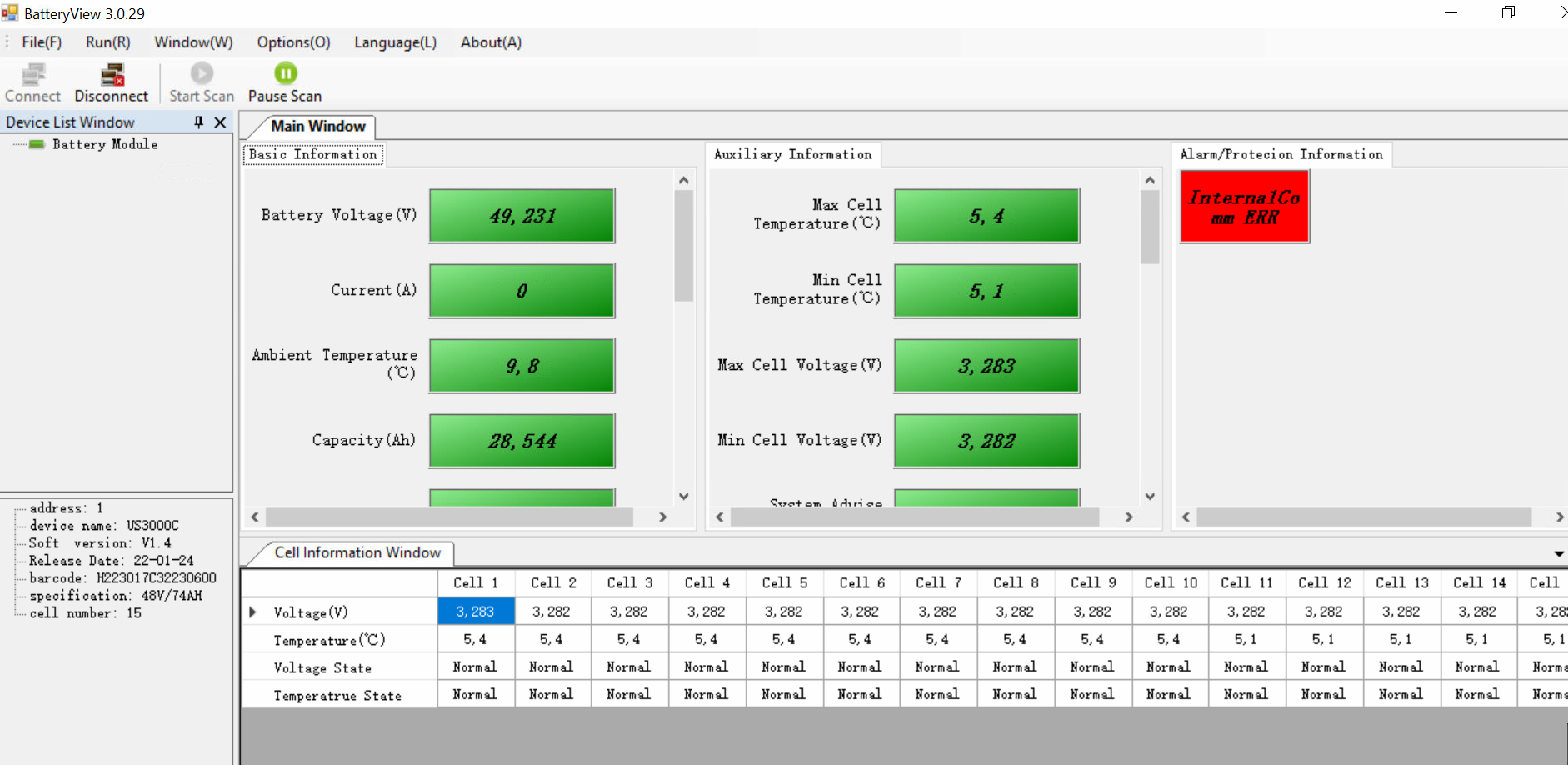
On certain US3000C and US5000 serial numbers running older firmware versions (below 1.7 on one batch, below 2.8 on another), the BMS ADC sampling circuit produces spurious cell voltage readings. A cell briefly reads 4,000 mV (4V) which is above the maximum safe cell voltage of 3.65V, triggering an Internal Failure alarm. The 4,000 mV reading is not real. The cell has not reached 4V. It is a BMS measurement error.
Pylontech engineers confirmed this in writing and released firmware patches 1.7 and 2.8 to fix it. The fix requires the BatteryView software and a custom RJ45 to RS232 cable, and must be performed with guidance from Pylontech support. Do not attempt firmware updates on Pylontech batteries without Pylontech’s explicit instruction, incorrect firmware flashing can permanently brick the BMS board.
How to confirm this is the cause:
On BatteryView logs, the cell that triggers the alarm reads 4,000 mV momentarily and then returns to normal in the next reading. This is impossible under real operating conditions (a genuine 4V cell would cause thermal runaway) and confirms a sampling error.
Fix: Contact Pylontech support and request the firmware update for your serial number range. Provide your battery serial numbers so they can confirm whether your units are in the affected batch.
Alarm 2: High Voltage Protection
What you see:
ALM light solid or flashing. Inverter may show “High Battery Voltage,” “OV Alarm,” or “Battery Voltage High.” On Victron, the GX shows “Battery: High voltage alarm.”
What the BMS is detecting:
One or more individual cells have reached or exceeded the maximum safe cell voltage of approximately 3.6 to 3.65V. The total module voltage at this point may only be 52V to 53V, well within the apparent safe range because the BMS is monitoring individual cells, not just terminal voltage.
This is why a multimeter across the battery terminals showing a “normal” 52V does not clear a High Voltage alarm. The problem is inside the module at the cell level.
The most common cause in installations:
The inverter battery type setting is configured for tubular lead-acid (float voltage 54.4V, equalization enabled) and the system was subsequently upgraded to Pylontech LiFePO4 without changing the inverter settings. The float and equalization voltages push individual cells above their 3.65V maximum.
Cell imbalance during charging. If cells within a module have drifted in capacity, the weakest cell reaches its maximum voltage before the others. The BMS sees that cell hit 3.65V, triggers the High Voltage alarm, and reduces or stops the charge current. The other cells may still be at 3.45V or 3.5V at this point. From the terminal voltage perspective, the module appears to be at 80 to 90% SOC.
Step-by-step fix:
Step 1: Check inverter settings. Confirm battery type is set to LiFePO4 or Lithium. Confirm charge voltage limit is 52.5V (recommended) and does not exceed 53.5V. Confirm float is disabled or set to 53.6V maximum. Confirm equalization is completely off.
Step 2: If inverter settings are already correct, the issue is cell imbalance. Allow the battery to reach full charge slowly over two to three consecutive full charge cycles. Do not interrupt charging before the battery reaches 100% SOC.
Step 3: If the alarm persists after three correct charge cycles, lower the CVL (charge voltage limit) in the inverter settings to 51.75V temporarily. This reduces the charge ceiling and allows the BMS more time to balance cells at the top without triggering the protection threshold. Gradually raise the CVL back toward 52.5V over subsequent weeks as the imbalance corrects.
Step 4: If the alarm still persists after two weeks of this approach, the battery has a structurally degraded cell. Contact Pylontech support.
Alarm 3: Low Voltage Protection (Under-Voltage)
What you see:
ALM light solid. Inverter shows “Low Battery Voltage,” “Battery Under Voltage,” or the system shuts down entirely. Some inverters show “Battery Open” when the BMS has fully disconnected the discharge path.
What the BMS is detecting:
The battery has discharged to the minimum safe voltage. For US-series batteries, the discharge cutoff is approximately 44.5V to 45V at the module level, which corresponds to a per-cell voltage of approximately 2.97V to 3.0V.
The BMS opens the discharge MOS switch. No current can leave the battery. The system cannot operate until charging begins and the voltage rises above the restart threshold.
Important distinction for Nigerian systems:
Low Voltage protection on a correctly sized system with BMS communication active should almost never occur. If the BMS is properly communicating with the inverter, it sends a progressively lower DCL as the battery depletes. The inverter switches to grid or generator input long before the hard cutoff is reached. If your system is triggering Low Voltage protection regularly, one of three things is wrong:
First: The battery bank is undersized for your load. The battery is being discharged faster than the BMS soft limits can signal the inverter to respond. Check your actual load vs. the sizing calculation in the Eneronix guide on How Many Batteries for a 5kVA Inverter.
Second: BMS communication is not active. The inverter is managing the battery on voltage estimation only, not receiving real-time DCL signals from the BMS. Without communication, the inverter does not receive the early warning that allows it to switch source before the hard cutoff. Read the Eneronix guide on Inverter Battery Communication Protocols for the full diagnosis process.
Third: The discharge cutoff voltage in the inverter settings is configured too low. If the inverter’s low battery cutoff is set below 45V, the inverter will continue drawing current past the point where the BMS wants to stop. The BMS then has no choice but to trigger hard protection.
Fix for regular Low Voltage protection:
Step 1: Verify BMS communication is active. Check the inverter display for cell-level data (individual cell voltages and BMS temperature). If not visible, communication is not active. Resolve this first.
Step 2: Set the inverter’s discharge cutoff to 46.4V (approximately 3.09V per cell), which is above the BMS hard cutoff threshold of 44.5V. This gives the inverter time to switch source before the BMS triggers.
Step 3: If Low Voltage protection still triggers after Steps 1 and 2, the bank is genuinely undersized. Add modules.
Recovering from a Low Voltage protection event:
The battery will not accept a high charge current immediately after a hard cutoff from over-discharge. The BMS implements a slow-charge recovery: it allows charging to begin at a reduced current (approximately 0.1C) until the cell voltages rise above the recovery threshold. On a 48V US3000C, this recovery charge may take 30 to 60 minutes before the battery accepts full charge current. Do not attempt to force the system with high charge currents during this period.
Alarm 4: Over-Current Protection
What you see:
ALM light solid. Inverter may show “Battery Over Current” or the system trips and refuses to restart. In some cases the battery appears dead: no output, no charge acceptance.
What the BMS is detecting:
The current flowing through the battery (either charge or discharge direction) has exceeded the module’s maximum rated current. For US2000C: 50A maximum continuous, 90A peak for 15 seconds. For US3000C: 74A maximum continuous, 90A peak for 15 seconds. For US5000: 100A maximum continuous, 150A peak.
The most common cause in Nigeria:
A single or dual-module bank is connected to a 5kVA inverter and the inverter attempts to start under full load, particularly with an air conditioner in the circuit. The startup inrush current of a 1.5HP AC compressor can reach 35 to 50A for 2 to 3 seconds. If this coincides with other running loads, the total current draw may exceed the single-module BMS threshold.
The second common cause:
The inverter capacitor bank drawing inrush current at startup when the battery is connected first and the inverter is powered on. This is specifically documented in the Pylontech installation guide: the startup inrush of the inverter capacitors looks like a dead short to the BMS. The correct startup procedure (press the red start button on the master battery, which activates the pre-charge circuit) prevents this. Bypassing the startup procedure by switching on the inverter without the pre-charge sequence triggers an immediate over-current protection event.
Fix:
Step 1: Follow the correct startup sequence. Switch on the battery rocker switches first. Then press and hold the red START button on the master battery for one second. Wait for all batteries to signal active (RUN lights on). Then power on the inverter. The pre-charge circuit limits the inrush current to the inverter capacitors.
Step 2: If over-current protection triggers during operation (not startup), verify that the parallel bank has enough modules to handle the peak load. A single US2000C module supports up to 50A continuous. A 5kVA inverter at full load needs 104A. You need at least three US2000C or two US3000C modules for adequate current headroom.
Step 3: If the battery trips in an existing correctly-sized system that previously ran without issues, inspect the power cable connections at the battery terminals. Loose or corroded terminals create resistance that forces the battery to deliver more current to compensate for voltage drop. Clean all terminal connections and torque to specification.
Alarm 5: Over-Temperature Protection
What you see:
ALM light flashing (warning stage) or solid (protection stage). System may continue briefly on the warning stage before shutting down if the temperature is not reduced.
What the BMS is detecting:
The cell temperature sensors inside the module have exceeded safe operating thresholds. For Pylontech US-series batteries, the charge over-temperature protection typically triggers around 45 to 50 degrees Celsius cell temperature. Discharge over-temperature triggers at a slightly higher threshold.
Why this is a serious issue specifically in Nigeria:
A Pylontech battery installed in a sealed, unventilated Nigerian equipment room during harmattan or peak dry season can reach internal temperatures of 40 to 45 degrees Celsius before the BMS even considers a protection event. At those ambient temperatures, the margin between normal operation and BMS shutdown is small. Field data from Nigerian LiFePO4 installations consistently shows that battery rooms without forced ventilation see 10 to 15% higher annual capacity degradation than properly ventilated rooms. The over-temperature protection event is the acute symptom. Accelerated degradation is the chronic one.
LiFePO4 cells are rated for 0 to 50 degrees Celsius operating temperature. At sustained temperatures above 35 degrees Celsius, every 8-degree increase roughly doubles the degradation rate. A battery specified for 6,000 cycles at 25 degrees Celsius may deliver fewer than 3,000 usable cycles if operated continuously at 40 degrees Celsius.
Fix:
Step 1: Move the battery to a ventilated location. The minimum requirement is that air can move freely around the module. A sealed cupboard with no airflow is not adequate.
Step 2: Add a small fan to the equipment room if natural ventilation is insufficient. A 20W fan running during the 8 to 10 hours of peak charging (when the inverter is also generating heat) is a low-cost fix with a significant impact on battery lifespan.
Step 3: Do not mount batteries directly against a west-facing wall in Nigerian sun. The wall surface temperature can reach 50 to 55 degrees Celsius during afternoon hours, heating the battery room from outside.
Step 4: For new installations, the battery room should be on the shaded (north or east) side of the building or in an interior space.
Alarm 6: Communication Loss (No BMS / Inverter Not Detecting Battery)
What you see:
Inverter display shows “No Battery Communication,” “BMS Not Connected,” or Error 61 (on Axpert/Voltronic inverters) or Error 67 (on Victron MPPT showing “No BMS”). The inverter may fall back to lead-acid voltage management mode.
What is happening:
The inverter is not receiving CAN bus or RS485 data packets from the master Pylontech battery. Without this data stream, the inverter cannot receive CVL, CCL, or DCL limits from the BMS. It manages the battery blindly on voltage estimation.
This is the most dangerous silent failure mode in Pylontech systems.
The battery may appear to work normally. Charging and discharging continue. But the inverter is applying the static lead-acid charge profile rather than the dynamic LiFePO4 profile sent by the BMS. Float voltage, equalization, and incorrect cutoff voltages may be applied for weeks or months before visible damage appears on the battery’s capacity.
The most common causes in Nigeria:
Wrong communication cable pinout. Different inverter brands require different RJ45 pin assignments on the communication cable. A Growatt cable wired for pins 1-3 will not communicate with a Victron inverter requiring a different configuration. Many Nigerian installers use generic RJ45 cables without verifying the pinout against the specific inverter’s documentation.
Wrong protocol selected on the inverter. The inverter must be set to “PylonLV” or “Pylontech” protocol (the exact menu label varies by brand). Setting it to “CAN” generically without selecting the Pylontech-specific protocol will fail communication even with the correct cable.
Wrong baud rate on the RS485 port. On US2000C and US3000C, DIP switch 2 controls the RS485 baud rate: 0 (down) = 115,200 baud, 1 (up) = 9,600 baud. Most inverters expect 115,200 baud. If this DIP switch has been changed from factory default, communication will fail.
Defective RJ45 connector. RJ45 connectors crimped in the field are a common failure point, especially in Nigerian installations where tools are sometimes shared between teams and crimping is done quickly. A connector where pin 1 has broken contact produces intermittent communication loss that is very difficult to diagnose without a cable tester.
Step-by-step fix:
Step 1: Verify the inverter battery protocol setting matches “PylonLV” or the equivalent Pylontech-specific setting for your inverter brand. Do not use a generic CAN or RS485 setting.
Step 2: Verify the communication cable pinout against your specific inverter’s documentation. The Pylontech manual publishes the correct pin assignment for the battery side. Your inverter manual publishes the expected pin assignment on the inverter side. Cross-reference them.
Step 3: Check DIP switch 2 on the master battery (US2000C/US3000C). It should be in the 0 (down/off) position for 115,200 baud RS485. Only change it to position 1 if your specific inverter explicitly requires 9,600 baud.
Step 4: Confirm the correct battery is acting as master. The master battery is identified by its Link 0 port being left free. Only the master battery’s CAN or RS485 port connects to the inverter. Slave batteries connect only to adjacent batteries in the daisy chain.
Step 5: Replace the RJ45 communication cable with a new, factory-crimped cable. Test communication before assuming any other cause.
How to confirm communication is restored: On the inverter display, navigate to the battery status screen. If BMS communication is active, you will see real-time cell voltages, BMS-reported temperature, and a state-of-charge percentage that updates dynamically as load changes. If the SOC increments in smooth fixed steps (100%, 99%, 98%…) rather than responding to load, communication is still not active and the inverter is still estimating.
Alarm 7: Battery Cannot Turn On / No Response From Battery
What you see:
You press the red START button but nothing happens. No lights, no beep, no response. Or the lights briefly illuminate and then go dark.
Three possible causes:
Cause A: Battery is in deep under-voltage shutdown.
If the battery has self-discharged over a long storage period to below approximately 40V, the internal BMS cannot power up from the residual cell voltage. The BMS electronics themselves need approximately 40 to 42V to initialise.
Fix: Apply a low-voltage recovery charge using an external 48V charger at 0.1C maximum (5A for a US2000C, 7.4A for a US3000C). Do not connect the inverter during recovery charging. Once the module voltage rises above 45V, the BMS should initialise normally and the module can be connected to the inverter.
Cause B: Internal BMS fuse has blown.
Pylontech batteries have a multi-level protection architecture. The final protection level is an internal fuse on the BMS board that permanently opens under extreme over-current or sustained over-voltage conditions. This fuse cannot be reset in the field. The battery will show no response to any input. This requires warranty replacement of the BMS board by Pylontech or an authorised service centre.
A blown internal fuse is relatively rare and typically indicates an installation error: reverse polarity connection, a charge voltage event well above 60V, or sustained severe over-current. Check installation records before pursuing warranty.
Cause C: Battery is in protect mode triggered by inverter capacitor inrush.
If the battery turns on briefly and immediately shuts off when connected to the inverter, the inverter capacitor bank is drawing inrush current that exceeds the BMS threshold. This is not a battery fault. Follow the correct pre-charge startup sequence: power on battery rocker switches, press and hold the START button for one second, wait for battery to stabilise, then power on the inverter.
Battery Protection Mode
What you see:
Battery shows RUN light (active), no ALM light (no alarm), but refuses to discharge. The inverter shows battery available but draws zero current from it. This is the “protect mode stuck” pattern that appears specifically after a high-voltage event.
What has happened:
The BMS triggered a protection event (most commonly high voltage from an incorrect inverter configuration) and has not received a signal to resume normal operation. The protection flag is stored in the BMS memory. Simply powering the battery off and on does not clear this flag if the triggering condition has not been resolved.
Fix:
Step 1: Resolve the triggering condition. If the battery went into protection from high voltage, reduce the inverter charge voltage limit to 52.5V and disable float before proceeding. If you restore the battery without fixing the underlying inverter settings, it will immediately re-enter protection.
Step 2: Power off the inverter completely.
Step 3: Turn off all battery rocker switches.
Step 4: Disconnect the power cables from the battery to the inverter (both positive and negative).
Step 5: Wait 5 minutes. This allows the BMS capacitors to fully discharge and the protection flag to clear from volatile memory.
Step 6: Reconnect the power cables.
Step 7: Switch on the battery rocker switches.
Step 8: Press and hold the START button on the master battery for one second. Wait for the RUN light to show stable operation.
Step 9: Power on the inverter.
If the protection mode reappears immediately after this sequence, the triggering condition has not been resolved. Do not proceed until the inverter settings are corrected.
Diagnostic Tools: Reading Pylontech Internal Data
When the LED indicators and inverter display are not giving you enough information, Pylontech batteries have a direct diagnostic interface.
The Console Port (RS232)
The RS232 port on every US-series battery provides a command-line interface for reading cell-level data, event logs, firmware version, and BMS state. Access requires a custom cable: an RJ45-to-RS232 or RJ45-to-USB serial cable with a specific pin mapping provided by Pylontech support.
With the cable connected and a terminal emulator (such as PuTTY on Windows) set to 115,200 baud, 8N1, type the word “pylon” at the prompt. Type “?” to see available commands. The most useful commands are:
“pwr” shows pack voltage, current, temperature, SOC, and SOH. “bat” shows individual cell voltages and temperatures. “log” shows the event log with timestamped fault codes.
The event log is what Pylontech support will ask for when you raise a warranty claim. Having this data ready significantly shortens the support resolution time.
BatteryView Software
Pylontech provides a Windows application called BatteryView that provides a graphical interface over the same RS232 connection. It displays cell voltage charts, event logs, and SOH history. BatteryView is not publicly downloadable. You must request it from Pylontech support at service@pylontech.com.cn along with your battery serial numbers.
Do not use unofficial versions of BatteryView downloaded from third-party sites. The firmware flashing feature in BatteryView can permanently damage the BMS if used incorrectly.
What Your Inverter Can Show Without External Tools
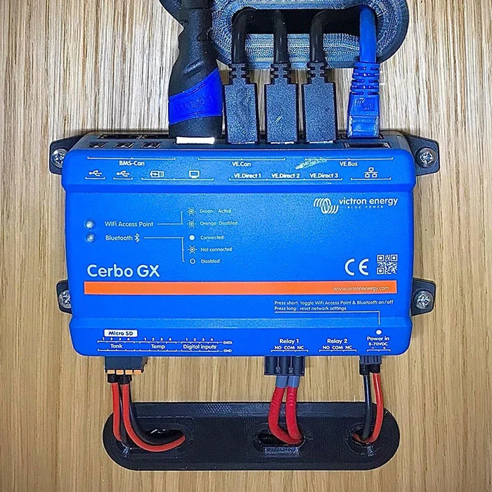
On Victron systems with a Cerbo GX or similar GX device, navigate to Device List, select the Pylontech battery, and open the Parameters screen. This shows CVL, CCL, and DCL in real time, BMS-reported min and max cell voltages, and alarm flags. This is the quickest in-field diagnostic without any additional hardware.
On Growatt and Deye systems with Wi-Fi monitoring, the ShineMonitor or SolarmanSmart apps show BMS communication status and battery alarm history. These logs are useful for pattern diagnosis (for example, identifying whether an Internal Failure alarm is appearing on a 3-day cycle).
Quick Diagnosis Reference
What You See
Most Likely Cause
Priority
Internal Failure, 3-day pattern
BMS sleep mode after idle period
Low: normal behaviour
Internal Failure on new battery
Cell imbalance, needs full charge cycles
Medium: self-resolving
Internal Failure on US3000C, random
Firmware sampling error
Medium: contact Pylontech
High Voltage alarm, new battery
Cell imbalance during first cycles
Medium: allow full charges
High Voltage alarm, LFP replacing tubular
Wrong inverter settings (float/equalise still on)
High: fix settings immediately
Low Voltage protection
Bank undersized or BMS comms not active
High: check sizing and comms
Over-current protection at startup
Startup sequence not followed or bank too small
High: follow pre-charge sequence
Over-temperature warning
Inadequate ventilation
High: improve airflow
No BMS communication
Wrong cable, wrong protocol, or DIP switch error
High: fix before operating
Battery will not turn on
Deep discharge, blown fuse, or startup sequence
Varies: see Alarm 7
Stuck in protection mode
Triggering condition not resolved before reset
High: fix inverter settings first
Frequently Asked Questions
What does the red light on my Pylontech battery mean?
A flashing red ALM light means the BMS has detected a condition approaching the limits of safe operation (alarm state). The battery continues operating. A solid red ALM light means the BMS has triggered protection and shut down the charge or discharge path. The battery is not operating normally. The combination of the red light with specific SOC LEDs lit indicates the type of protection. Consult your specific model’s LED indicator table in the manual for the exact combination codes.
Why does my Pylontech show “Internal Failure” on a brand new system?
On a new installation, Internal Failure almost always indicates one of two things: the BMS sleep mode has triggered because the backup system has not cycled in 3 days (common on systems where NEPA supply is reliable), or cell imbalance during the first charge cycles. In both cases, no physical fault has occurred. Allow the battery to complete several full charge cycles reaching 100% SOC and the alarm should resolve. If it does not resolve after five full charge cycles, contact Pylontech support.
My Pylontech battery shows a red alarm light but the system is still working. Is this dangerous?
A flashing red ALM light is a warning, not a protection event. The battery is still operating and the cells are not in immediate danger. You should investigate and resolve the cause within a reasonable timeframe (days, not months), but there is no immediate risk to the system. A solid red ALM light is more urgent: the BMS has intervened and the battery is not operating normally.
How do I reset a Pylontech battery after a protection event?
Power off the inverter. Turn off all battery rocker switches. Disconnect the power cables from the inverter terminals. Wait 5 minutes. Reconnect the cables. Switch on the rocker switches. Press and hold the START button on the master battery for one second. Wait for stable RUN LED operation. Power on the inverter. Do not reset without first resolving the condition that caused the protection event, or the protection will trigger again immediately.
Why does my Pylontech battery show correct SOC on the inverter but the runtime is much shorter than expected?
This symptom correct-looking SOC with shorter-than-expected runtime — almost always indicates the inverter is estimating SOC from terminal voltage rather than receiving it from the BMS via CAN or RS485. When BMS communication is not active, the SOC display is a smooth interpolation from voltage, not an accurate reading. The actual usable capacity may be significantly lower than the displayed percentage, especially if the battery has experienced cell imbalance or thermal degradation. Verify BMS communication is active by checking whether the inverter display shows cell-level data (individual cell voltages and BMS temperature). If not visible, communication is not active.
Can I run Pylontech batteries without BMS communication connected to the inverter?
Technically yes. The battery will charge and discharge. But the inverter will manage it on voltage estimation only, applying the static profile for whatever battery type is selected in the menu. If the profile does not match LiFePO4, cells will be damaged over time. Even if the profile is set to LiFePO4, the dynamic limits (CCL, DCL, CVL) that protect cells during temperature extremes, cell imbalance events, and high-load conditions will not be active. Pylontech batteries are designed to operate with BMS communication active. Running without it voids the protection mechanism that justifies the battery’s 10-year warranty.
Why does my Pylontech battery go into protection mode when I connect it to the inverter?
This is almost certainly the inverter capacitor inrush problem. When the inverter is already powered on and the battery is connected, the inverter capacitor bank draws a sudden large current to charge from the battery voltage. This current spike is large enough to trigger the BMS over-current protection. The correct sequence is to connect the battery cables first while the inverter is off, then use the battery’s red START button (which activates the internal pre-charge circuit that limits inrush current), and then power on the inverter. See Alarm 4 (Over-Current Protection) for the full procedure.
What is the difference between an alarm and a fault on a Pylontech battery?
An alarm (flashing ALM LED) indicates that a parameter is approaching the safe operating boundary. The BMS has detected it and is warning the system, but the battery remains operational. A fault or protection event (solid ALM LED) means the BMS has exceeded the boundary and has opened the charge or discharge MOS switch, stopping operation. Alarms are often self-resolving. Protection events require the triggering condition to be resolved and a manual reset procedure before the battery resumes operation.
How do I know if my Pylontech battery needs to be replaced?
A battery that needs replacement shows one or more of these conditions: consistent capacity delivery below 70% of rated usable capacity after multiple full charge cycles; persistent Internal Failure alarms that do not resolve after firmware update and repeated full charge cycles; a cell that shows 0V in BatteryView diagnostics (a genuine dead cell, not a sampling error); or a BMS that has triggered the internal fuse protection (no response to any input, confirmed by Pylontech support). Degraded performance alone is not sufficient reason for warranty replacement — the battery must be operating outside its published specifications. Document all alarm events and contact Pylontech at service@pylontech.com.cn with serial numbers and BatteryView log files.
Conclusion
Most Pylontech alarm events in Nigerian solar installations fall into three categories: incorrect inverter settings, inadequate BMS communication, or cell imbalance from incomplete charge cycles. Very few are genuine hardware failures.
The diagnosis path is always the same: read the LED combination correctly, check inverter settings first, verify BMS communication is active, and only then suspect the battery hardware itself.
Every alarm covered in this guide has a specific and identifiable cause. The BMS is not failing randomly. It is detecting real conditions and reporting them through the only interface it has: the ALM light and the communication bus. Your job is to read what it is telling you accurately.
For everything on configuring your hybrid inverter correctly for Pylontech batteries from day one and preventing these alarms before they occur, read the Eneronix guide on Hybrid Inverter Battery Compatibility.
I am Engr. Ubokobong Ekpenyong, a solar specialist and lithium battery systems engineer with over five years of hands-on experience designing, assembling, and commissioning off-grid solar and energy storage systems. My work focuses on lithium battery pack architecture, BMS configuration, and system reliability in off-grid and high-demand environments.
Contains information related to marketing campaigns of the user. These are shared with Google AdWords / Google Ads when the Google Ads and Google Analytics accounts are linked together.
90 days
__utma
ID used to identify users and sessions
2 years after last activity
__utmt
Used to monitor number of Google Analytics server requests
10 minutes
__utmb
Used to distinguish new sessions and visits. This cookie is set when the GA.js javascript library is loaded and there is no existing __utmb cookie. The cookie is updated every time data is sent to the Google Analytics server.
30 minutes after last activity
__utmc
Used only with old Urchin versions of Google Analytics and not with GA.js. Was used to distinguish between new sessions and visits at the end of a session.
End of session (browser)
__utmz
Contains information about the traffic source or campaign that directed user to the website. The cookie is set when the GA.js javascript is loaded and updated when data is sent to the Google Anaytics server
6 months after last activity
__utmv
Contains custom information set by the web developer via the _setCustomVar method in Google Analytics. This cookie is updated every time new data is sent to the Google Analytics server.
2 years after last activity
__utmx
Used to determine whether a user is included in an A / B or Multivariate test.
18 months
_ga
ID used to identify users
2 years
_gali
Used by Google Analytics to determine which links on a page are being clicked
30 seconds
_ga_
ID used to identify users
2 years
_gid
ID used to identify users for 24 hours after last activity
24 hours
_gat
Used to monitor number of Google Analytics server requests when using Google Tag Manager
1 minute
You can find more information in our Cookie Policy and .


")
")


