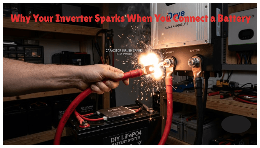
The spark you see when connecting a battery to an inverter is not normal or harmless. It is a capacitor inrush current event that stresses your BMS every single time it happens. This article explains the physics, the damage mechanism, and how a simple pre-charge circuit eliminates the problem permanently.
Why Your Inverter Sparks When You Connect a Battery
Every experienced solar installer has seen it. You connect the battery positive cable to the inverter DC input terminal, and there is a visible arc, a pop, sometimes a spark that makes you flinch. The system powers up fine. You tell the customer everything is normal. You move on.
It is not normal. And the fact that the system powers up fine after it does not mean nothing happened. Something happened every time, to a component inside the BMS that cannot tell you it is being slowly degraded, until it cannot perform its protective function any more.
That component is the MOSFET switch inside the BMS. The spark is caused by a rapid current surge called capacitor inrush, and understanding what it is, where it comes from, and what it does to the BMS over hundreds of identical startup events is what separates installers who have mysterious BMS failures at the 18-month mark from installers who do not.
This article explains the physics of inverter capacitor inrush, shows you exactly how much current is actually flowing in that half-second spark, documents the MOSFET degradation pathway it creates, and gives you every detail needed to build a pre-charge circuit that costs under 3,000 naira and eliminates the problem permanently.
TL;DR
What this covers: why inverters spark when connected to batteries, what the inrush current does to your BMS over time, and how to build a pre-charge circuit that eliminates it. Who it is for: DIY builders, solar installers, and anyone whose BMS keeps tripping when the inverter starts up. Key takeaways: – The spark is capacitor inrush current. It is not normal.
It damages BMS MOSFETs every time it happens. – A pre-charge circuit costs under 3,000 NGN and takes 30 minutes to install. There is no good reason not to have one. – Raising the BMS OCP threshold to stop inrush trips is the wrong fix. It makes the damage invisible, not stop. – The MOSFET degradation from inrush is cumulative and silent. It shows up as unexplained BMS failures at 18 months. Estimated read time: 12 to 15 minutes.
Why Inverters Have Large Capacitors and What Happens When You Connect a Battery
Modern inverters are not simple switches. They are switching power converters that rapidly chop DC current into high-frequency pulses, which are then shaped into the AC waveform that your appliances use. The fundamental requirement of this switching process is a stable, low-impedance DC source at the inverter’s input terminals.
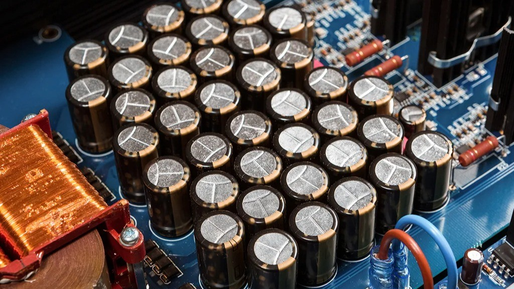
To create this stable DC source internally, inverter designers place large electrolytic capacitors directly across the DC bus inside the inverter. These capacitors act as a local energy reservoir. When the inverter’s switching transistors fire, they draw current from the capacitors in microsecond pulses. Between pulses, the battery (or solar input) replenishes the capacitors. The capacitors smooth the rapid current demand and prevent the switching action from creating voltage spikes that would damage the inverter’s transistors.
A 5kVA inverter typically contains 5,000 to 15,000 microfarads of DC bus capacitance. Some larger models have even more. This capacitance is proportional to the inverter’s power rating and switching architecture. You can find this figure in the inverter’s service manual or by measuring between the DC input terminals with a capacitance meter when the inverter is powered off.
Now here is the problem. When the inverter is off and you connect the battery, the DC bus capacitors are completely discharged. They are at 0V. The battery terminal is at 58.4V. You have connected a 0V capacitor bank to a 58.4V low-impedance source. The capacitors will charge to 58.4V. And they will do it as fast as physics allows.
The charging speed is limited by one thing: the resistance of the circuit between the battery and the capacitors. In a well-installed system with 50mm2 copper cable, a properly torqued ANL fuse, and a low on-resistance BMS MOSFET, that total circuit resistance is approximately 0.03 to 0.1 ohms. At 58.4V, the peak charging current is I = V/R = 58.4 / 0.07 = 834A. That is what creates the spark.
| KEY TAKEAWAY | The spark is 500 to 1,000 amps flowing for 5 to 20 milliseconds. It is not a small event. Every time it happens, it passes through your BMS MOSFET switches. The MOSFETs are not designed for repeated 800A transients. They degrade. |
How Much Inrush Current Is Your System Actually Generating?
The inrush current varies by system. Larger inverters have bigger capacitor banks and generate higher inrush. Higher pack voltages also increase the inrush for the same capacitance. The following table gives realistic estimates for common Nigerian solar system configurations.
| System | Pack Voltage | Typical Inverter Capacitance | Estimated Inrush Current | Risk Without Pre-Charge |
| 1 kVA, 12V inverter, 100Ah LiFePO4 | 14.6V | 1,000 to 5,000 uF (typical small inverter) | 15 to 75A peak | Low. Spark visible but manageable. No OCP trip on most BMS units. |
| 3 kVA, 48V inverter, 200Ah LiFePO4 | 58.4V | 2,000 to 8,000 uF | 100 to 400A peak | Moderate to high. OCP trips common. MOSFET stress significant. |
| 5 kVA, 48V inverter, 200Ah LiFePO4 | 58.4V | 5,000 to 15,000 uF | 200 to 700A peak | High. Consistent OCP trips without pre-charge. MOSFET degradation accelerated. |
| 10 kVA, 48V inverter, 400Ah LiFePO4 | 58.4V | 10,000 to 30,000 uF | 400 to 1,500A peak | Very high. Pre-charge is non-negotiable. Without it, BMS failure within 12 months is likely. |
| 5 kVA, 96V high-voltage inverter | 109.5V | 3,000 to 10,000 uF | 150 to 600A peak | High despite lower capacitance because voltage is higher. Pre-charge still required. |
These numbers are consistent with the capacitor inrush current calculations published in application notes by both Texas Instruments for their gate driver ICs (TI application note SLVA681 covers capacitive load inrush specifically) and Infineon Technologies in their power MOSFET application notes (Infineon AN2015-17 documents inrush current effects on power MOSFET safe operating area). Both are publicly available through the respective manufacturer websites.
The BMS current rating calculation that must account for the inverter’s rated current demand is covered in our article how to size a BMS correctly. The inrush scenario in this article is a separate but related consideration: the BMS must handle both the rated operating current and the startup inrush event.
What the Inrush Actually Does to Your BMS
The BMS MOSFET switch sits in the current path between the battery cells and the inverter. When the inverter is first connected, the inrush current flows through the MOSFET. The MOSFET is in a conducting state at this point (it opened to connect the battery to the inverter). The inrush current is not being switched by the MOSFET. It flows directly through the conducting channel.
At 834A through a MOSFET with an on-resistance of 1 milliohm, the power dissipated is P = I2 x R = 834 squared x 0.001 = 695 watts. This dissipation lasts approximately 10 to 20 milliseconds. The thermal energy deposited in the MOSFET junction is 695W x 0.015s = 10.4 joules in a single startup event.
The MOSFET’s junction thermal impedance determines how much its temperature rises from this pulse. For typical BMS MOSFETs with transient thermal impedance around 0.5 degC/W at 20ms pulse width, the junction temperature rise is approximately 695 x 0.5 = 347 degC above ambient. This briefly exceeds the MOSFET’s absolute maximum junction temperature rating of 150 to 175 degC for most silicon power MOSFETs.
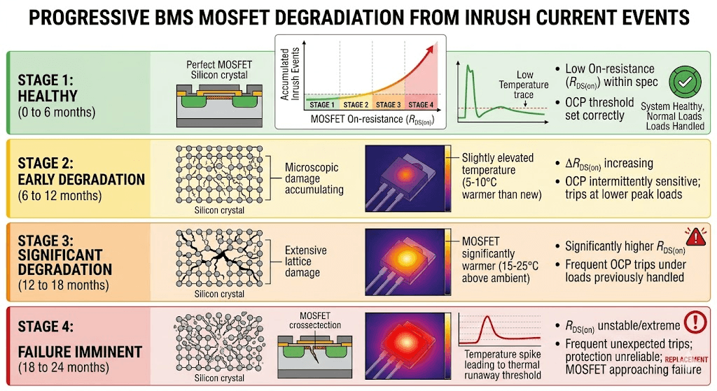
The MOSFET does not fail immediately. The junction temperature spike is local and brief. The MOSFET recovers. But each spike causes microscopic damage to the silicon crystal structure of the MOSFET channel, a phenomenon documented in JEDEC standard JESD22-A108 on temperature cycling degradation in semiconductor devices. The damage accumulates. After 200 to 500 such startup events, the MOSFET on-resistance has increased measurably. After 500 to 1,000 events, protection reliability is compromised.
| Degradation Stage | Observable Signs | Symptom at System Level |
| Stage 1: Healthy (0 to 6 months) | Normal. On-resistance within specification. No measurable performance impact. | OCP threshold set correctly. No inrush-related trips. |
| Stage 2: Early degradation (6 to 12 months) | On-resistance begins increasing. MOSFET temperature under normal load slightly elevated. Thermal imaging may show MOSFET running 5 to 10 degC warmer than at installation. | OCP may trip at higher loads than previously. BMS appears intermittently sensitive. |
| Stage 3: Significant degradation (12 to 18 months) | On-resistance noticeably higher. MOSFET temperature during normal load 15 to 25 degC above ambient. BMS app may show elevated internal temperature. | Regular OCP trips under loads that were previously handled without issue. Customer reports intermittent disconnects. |
| Stage 4: Failure imminent (18 to 24 months) | MOSFET approaching thermal runaway threshold under normal load. On-resistance unstable. Protection functions unreliable. | Frequent unexpected BMS trips. System barely operational under any significant load. BMS replacement required. |
The symptoms that appear at each degradation stage are covered in detail in our article on signs of a failing BMS. If your BMS is already showing Stage 2 or Stage 3 symptoms, the inrush damage may already be underway. Installing a pre-charge circuit now will prevent further damage but will not reverse what has already occurred.
The OCP Threshold Trap:
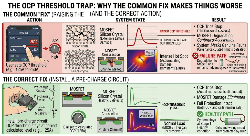
The most common response to inrush-triggered BMS OCP trips is to raise the OCP threshold. The installer sets the BMS OCP from 125A to 250A or higher. The OCP trips stop. The problem appears solved.
It is not solved. It is hidden.
The OCP protection fires when the BMS detects current exceeding the threshold. By raising the threshold, the installer has told the BMS to ignore currents that previously triggered a trip. The inverter capacitors are still charging through the BMS MOSFETs at exactly the same inrush current on every startup. The MOSFET stress is identical. The difference is that the BMS no longer reports that anything unusual is happening.
The raised OCP threshold also removes genuine overcurrent protection. If a real fault occurs and current exceeds the original OCP threshold but stays below the raised threshold, the BMS will not trip. The cells and wiring are exposed to sustained overcurrent that the protection was specifically designed to interrupt.
This situation is covered in our article on
BMS protection explained: every protection function has a specific purpose, and defeating any one of them to solve an installation problem creates a gap in the protection envelope that can have serious consequences.
The correct fix is a pre-charge circuit that prevents the inrush from reaching the BMS MOSFETs at all. The OCP threshold stays at its properly calculated level. The MOSFET stress stops. The protection remains intact.
| THE RULE | If your BMS keeps tripping OCP at inverter startup, the correct action is to install a pre-charge circuit. Not to raise the OCP threshold. Not to use a slower fuse. Not to accept the trips as normal operation. A pre-charge circuit. |
Five Ways to Build a Pre-Charge Circuit
There is no single correct pre-charge circuit design. The right approach depends on your specific installation, budget, and whether the system restarts automatically or requires manual intervention. The following table covers every practical pre-charge method with an honest assessment of each.
| Pre-Charge Method | How It Works | Pros | Cons |
| Resistor + manual bypass switch | A resistor in series with P+ cable. Installer manually shorts the resistor with a switch after 1 to 2 seconds. No relay required. | Simplest and cheapest. Cost: 500 to 1,000 NGN. | Requires operator presence at every inverter startup. Not suitable for automated systems. If the operator forgets to close the bypass, the system runs permanently through the resistor at reduced efficiency. |
| Resistor + time-delay relay | A resistor in series with P+, bypassed by a relay that closes automatically after 500ms to 1 second via a 555-timer or commercial time-delay relay module. | Fully automatic. Works on every startup without operator intervention. Cost: 2,000 to 5,000 NGN. | Slightly more complex to wire than the manual version. Timer must be set correctly. If timer fails open, pre-charge never bypasses and the system runs through the resistor indefinitely. |
| Resistor + NTC thermistor (passive pre-charge) | NTC (negative temperature coefficient) thermistor in series with P+. Cold resistance is high (limits inrush). As thermistor warms from current flow, resistance drops, allowing full current. | No relay, no timer, no external control. Self-regulating. Cost: under 1,000 NGN. | NTC thermistor resistance at operating temperature is not zero, so there is always some small continuous voltage drop. For frequent restarts, the thermistor may not cool fully between startups, reducing pre-charge effectiveness on rapid cycling. |
| Dedicated pre-charge relay output from BMS | Some premium BMS units (including certain Seplos and REC BMS models) have a dedicated pre-charge relay output that fires before the main MOSFET bank opens. The BMS controls the entire sequence automatically. | Fully integrated. No external components. Pre-charge is managed by the BMS firmware. | Only available on specific premium BMS models. Not available on JK BMS or standard Daly. Requires a BMS with this specific feature. |
| Inverter-integrated soft start | Some inverter models include a built-in soft-start circuit that limits the charging rate of their own DC bus capacitors on power-up. Check the inverter datasheet for ‘battery soft-start’ or ‘DC bus pre-charge’ specification. | No external components required. Pre-charge handled by the inverter itself. | Not universal. Most Chinese hybrid inverters in the Nigerian market do not include this feature. Verify in the specific inverter datasheet before assuming it is present. |
For most Nigerian DIY LiFePO4 solar installations, the resistor plus time-delay relay is the correct choice. It is automatic, inexpensive, reliable, and does not require any special features from the BMS or inverter. The 555-timer relay module is widely available in Nigerian electronics markets for under 2,000 NGN and requires no electronics knowledge to configure beyond setting the time delay potentiometer.
The Complete Pre-Charge Calculation: Every Number You Need
Pre-charge circuit design involves three calculations: the resistor value, the power rating, and the relay bypass timing. None of these is complex. All three are done with arithmetic.
| Parameter | Value / Calculation | Notes |
| Pack voltage (V_battery) | 58.4V | Fully charged 16S LiFePO4 pack |
| Target inrush current (I_target) | 10A | Conservative target for zero OCP trips and minimal MOSFET stress |
| Pre-charge resistor (R) | 58.4V / 10A = 5.84 ohms. Use 10 ohm for margin. | Higher resistance = lower peak current = longer charge time. 10 ohm gives 5.84A peak. |
| Pre-charge time constant (tau) | tau = R x C. For R=10 ohm, C=5,000uF: tau = 10 x 0.005 = 0.05 seconds. | Capacitors are charged to 63% of pack voltage in one tau, 95% in 3 tau (0.15s), 99% in 5 tau (0.25s). |
| Relay bypass timer setting | 500ms to 1,000ms (10 to 20 x tau) | Gives full capacitor charging with generous margin. No need to set it shorter. |
| Energy dissipated in resistor | E = 0.5 x C x V2 = 0.5 x 0.005 x 58.42 = 8.5 joules per pre-charge event. | Duration 0.25 seconds max. Peak power = V2/R = 58.42/10 = 341W but only for 250ms. A 10W resistor handles this easily. |
| Resistor power rating | 10W wirewound minimum. 20W for frequent restart scenarios. | The 10W rating is for continuous service. The pre-charge pulse is brief. Even a 5W resistor handles a single pre-charge event. Use 10W for reliability margin. |
| Relay contact rating | 300A minimum (equal to BMS current rating or above). | The bypass relay carries full system current after closing. It must be rated for DC switching at the pack voltage. |
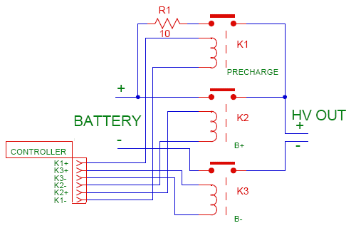
The Complete Circuit Description for a 5kVA 48V System
With the calculations confirmed, the pre-charge circuit for a standard Nigerian 5kVA 48V Deye installation is:
- A 10-ohm 10W wirewound resistor in series with the P+ cable between the BMS P+ terminal and the inverter DC positive input.
- A 12V or 24V coil relay with 300A DC-rated contacts, wired to bypass the resistor. The relay coil is controlled by a 555-timer module set to 500ms to 1 second delay from the moment power is applied.
- The timer module is powered from a 12V auxiliary supply or from a small buck converter stepping down from the 48V pack.
- When the system starts: current flows through the resistor, limiting inrush to approximately 5.8A. After 500ms to 1 second, the timer closes the relay, shorting the resistor. Normal operation at full current begins.
Total component cost in Nigeria: 10-ohm 10W resistor (300 to 500 NGN), 555 timer delay relay module (1,500 to 2,500 NGN), relay socket and wiring (500 to 1,000 NGN). Total under 4,000 NGN. This is one of the highest-value investments in the entire battery build.
Installing the Pre-Charge Circuit: Where It Goes and How It Connects
The pre-charge circuit connects between the BMS P+ output terminal and the inverter DC positive input terminal. It is in series with the main P+ cable, not parallel to it. The resistor must carry the full inrush current (briefly) and the relay contacts must carry the full continuous operating current once bypassed.
Wiring Sequence
- BMS P+ terminal connects to one end of the pre-charge resistor.
- The other end of the resistor connects to both the normally-open contact of the bypass relay AND continues to the inverter DC positive input terminal.
- The relay contact bridges the resistor directly: one contact to the BMS P+ terminal side of the resistor, the other contact to the inverter DC input side.
- The relay coil connects to the timer module output and timer module common. The timer module is powered from a 12V auxiliary supply.
- Timer module input trigger is connected to the same point as the BMS P+ output (it activates when the BMS connects the pack to the circuit).
The physical pre-charge assembly can be mounted on a small DIN rail inside the battery enclosure or on the wall of the generator room adjacent to the battery and inverter. Keep all connections accessible for inspection. Label the resistor and relay clearly with their function.
For the full wiring context including the ANL fuse placement relative to the pre-charge circuit, see our article on busbar sizing, cable sizing, and fuse selection. The fuse is between the battery B+ terminal and the BMS B+ terminal. The pre-charge circuit is between the BMS P+ terminal and the inverter. These are different segments of the same power path.
Deye, Growatt, Victron: What Each Inverter Needs
Deye SUN-xK-SG Series
The Deye SUN-5K-SG03LP1 and similar models in the SUN-xK-SG series use approximately 4,700 to 6,800 microfarads of DC bus capacitance based on reverse-engineering measurements documented by the DIY solar community. Inrush current at 58.4V pack voltage with 0.07 ohm circuit resistance peaks at approximately 550 to 800A.
Deye does not include a pre-charge circuit or document the capacitor value in their consumer-facing manuals. The SUN-xK-SG installation manual available on the Deye website at deye.com.cn/global recommends connecting the battery cable ‘firmly’, with no mention of inrush or pre-charge. This is a gap in their installation guidance that experienced solar engineers routinely correct by adding external pre-charge circuits.
For Deye systems: use a 10-ohm resistor with a 500ms relay bypass. This works for all models in the SUN-xK-SG range.
Growatt SPF and SPH Series
Growatt SPF 5000TL and SPH series inverters have similar DC bus capacitance to Deye. The Growatt installation documentation available at growatt.com also does not specifically address inrush or recommend pre-charge circuits. Field experience with Nigerian installations shows inrush behaviour identical to Deye systems.
Use the same 10-ohm, 500ms relay bypass pre-charge circuit as the Deye recommendation.
Victron MultiPlus and Quattro
Victron is more transparent than most Chinese inverter manufacturers about their DC input characteristics. The Victron MultiPlus-II 48/5000 datasheet available at victronenergy.com documents a maximum battery cable length and wire gauge partly to manage inductance in the inrush circuit. However, Victron does not include a pre-charge circuit in the MultiPlus package.
For Victron systems with DIY LiFePO4 packs: the same 10-ohm, 500ms relay bypass pre-charge circuit is the correct specification. For sealed Pylontech batteries connected to Victron, the Pylontech integrated BMS manages its own soft-start sequence, reducing but not eliminating the need for external pre-charge consideration.
For the Victron communication configuration that enables the BMS and inverter to work as a coordinated system (separate from pre-charge), our article on BMS-to-inverter communication troubleshooting covers the VE.Can setup and verification procedure.
Three Pre-Charge Mistakes to Avoid
| MISTAKE 1 | Using a relay with AC-rated contacts for DC switching. Relay contact ratings for AC and DC are very different. A relay rated at 30A AC may be rated for only 5 to 10A DC at 48V because DC arc suppression is significantly harder than AC (AC naturally crosses zero current 100 times per second, which extinguishes arcs automatically. DC does not). For DC battery circuits, always use relays with DC contact ratings specified for your voltage and current. SPDT power relays rated for 48VDC at 200A+ are available from suppliers including TE Connectivity and Omron, referenced at te.com and components.omron.com. |
| MISTAKE 2 | Using an undersized resistor that burns out during the pre-charge pulse. The energy deposited in the pre-charge resistor per startup event is 0.5 x C x V2. For a 5kVA inverter with 10,000 microfarad capacitance at 58.4V: 0.5 x 0.01 x 58.42 = 17 joules. A 5W resistor can absorb about 5 joules without damage for a brief pulse. 17 joules will burn it. Use a 10W wirewound resistor for standard solar systems and 20W for larger inverters or systems that restart frequently. |
| MISTAKE 3 | Setting the timer delay too short. A 100ms delay allows only 2 RC time constants for capacitor charging. At this point, the capacitors are at approximately 86% of pack voltage. When the relay closes, the remaining 14% charges through the relay contacts, creating a smaller but still significant current spike. Set the delay to 500ms minimum (10 RC time constants) to ensure capacitors are fully charged before the relay closes. |
The 3,000 Naira Investment That Saves Your BMS
A pre-charge circuit costs under 3,000 naira in components and takes 30 minutes to install. It eliminates the inrush current event that otherwise stresses your BMS MOSFET switches at every inverter startup for the life of the installation.
The installer who does not put in a pre-charge circuit will, at some point, be diagnosing a BMS that trips unexpectedly under normal loads, replacing a BMS that failed at 18 months for no apparent reason, or explaining to a customer why a 35,000 naira JK BMS needs replacement after less than two years of service.
The installer who puts in the pre-charge circuit will not have those conversations.
For the commissioning protocol that verifies all aspects of the power circuit including pre-charge operation after installation, our hybrid solar system commissioning checklist includes pre-charge circuit verification as a commissioning checkpoint.
Frequently Asked Questions
Why does my inverter spark when I connect the battery?
The spark happens because your inverter contains large capacitors on its DC input stage. When you connect a charged battery to an uncharged capacitor bank, current flows instantly to equalise the voltage. The current is limited only by the resistance of the connecting circuit, which is very low in a well-wired battery system. This creates a brief but intense current spike that causes the visible arc at the connection point. The physics is identical to touching two charged capacitors together, which is exactly what is happening. The pre-charge circuit solves this by placing a current-limiting resistor in the circuit before the full battery voltage is applied.
Is it dangerous to connect a battery to an inverter without a pre-charge?
The spark itself is not immediately dangerous to people in most low-voltage DC systems below 60V. However, it is damaging to equipment over time. The inrush current spike stresses the BMS MOSFET switches, can trip the BMS OCP protection at every startup, and can cause contact arcing at the battery terminal connections that progressively erodes the contact surfaces. For systems above 60V (high-voltage inverters), the arc energy at connection is more significant and presents a greater risk of sustained arcing if contact quality is poor.
What size pre-charge resistor do I need?
For a 48V LiFePO4 system targeting 10A maximum inrush: R = V_battery / I_limit = 58.4V / 10A = 5.84 ohms. Use a 10-ohm wirewound resistor for margin. For a 24V system: R = 29.2V / 10A = 2.92 ohms, use 5 ohms. For a 12V system: R = 14.6V / 10A = 1.46 ohms, use 2 ohms. Power rating: 10W for most solar storage applications with infrequent restarts. Use 20W if the inverter restarts frequently (multiple times per hour).
How long should the pre-charge resistor be in circuit before bypassing?
The pre-charge time should be at least 5 to 10 times the RC time constant (tau = R x C). For a 10-ohm resistor and a 5,000 microfarad inverter capacitor bank: tau = 10 x 0.005 = 0.05 seconds. The relay should bypass after 500ms minimum (10 times tau). In practice, 500ms to 1 second covers all common inverter capacitor sizes without being so long that the pre-charge period is inconvenient.
Does my Deye or Growatt inverter need a pre-charge circuit?
Yes. Both the Deye SUN-xK-SG series and Growatt SPF/SPH series use large electrolytic capacitors on their DC bus. Neither includes a factory-installed pre-charge circuit for the battery connection. The inverter manuals for these products do not explicitly warn about inrush, but the physics applies regardless. Every installation of a DIY LiFePO4 pack with a Deye or Growatt inverter should include a pre-charge circuit. The component cost is under 3,000 NGN.
Can the BMS protect itself from inrush without a pre-charge circuit?
Not effectively. The BMS OCP protection uses either firmware detection (relatively slow, 500 microseconds to milliseconds) or hardware comparator detection (under 200 microseconds). Both are slower than the inrush current rise time. The capacitor begins charging before the BMS OCP can respond. The MOSFET absorbs the inrush energy before the protection fires. The BMS may then trip OCP after the peak, but the MOSFET has already been stressed. Repeated inrush events cause cumulative MOSFET degradation that the OCP trip does not prevent.
What happens if I raise the BMS OCP threshold to stop inrush trips?
Raising the OCP threshold to accommodate inrush current makes the inrush trips stop, but it does not solve the underlying problem. The inverter capacitors are still charging through the BMS MOSFETs at full inrush current on every startup. The MOSFET stress is identical whether the OCP fires or not. The only change is that you have removed the warning signal that the inrush was happening. The MOSFET degradation continues silently. This is a common workaround that makes a problem invisible rather than solved, and the BMS hardware failure it eventually produces is significantly worse than the occasional OCP trip that prompted the threshold change.
Does a Pylontech battery need a pre-charge circuit?
Pylontech batteries include a factory-integrated BMS with pre-charge management built into their power-up sequence. The Pylontech BMS manages the connection to the inverter through its own controlled ramp-up that limits inrush. If the Pylontech battery is correctly connected and communicating with the inverter, you do not need an external pre-charge circuit. However, if the Pylontech is being connected to an inverter with incorrect battery type settings or without the RS485 communication cable, the factory pre-charge sequence may not function as designed.
External References (Also Linked in Article Body)
- Texas Instruments — SLVA681: Capacitive load inrush current and MOSFET safe operating area
- Infineon Technologies — AN2015-17: Power MOSFET transient thermal impedance and safe operating area under inrush conditions
- JEDEC — JESD22-A108: Temperature Cycling degradation in semiconductor devices

I am Engr. Ubokobong Ekpenyong, a solar specialist and lithium battery systems engineer with over five years of hands-on experience designing, assembling, and commissioning off-grid solar and energy storage systems. My work focuses on lithium battery pack architecture, BMS configuration, and system reliability in off-grid and high-demand environments.