How to Connect LiFePO4 Cells in Parallel Safely
Quick Answer
What this covers: how to safely connect LiFePO4 cells in parallel to increase pack capacity, including voltage matching, equalisation current management, wiring topology, BMS requirements, and cable length principles. Who it is for: DIY battery builders scaling from a single-string pack to a multi-string parallel configuration for higher capacity. Key takeaways: Voltage match cells to within 50mV before connecting in parallel. Above 300mV difference, use a limiting resistor. Equal cable lengths from each parallel string to the bus is non-negotiable. Unequal lengths create unequal current sharing. Series-first-then-parallel (one BMS per string) is safer and more diagnostic than parallel-first-then-series. Never mix cells of different ages, capacities, or internal resistance in the same parallel group. Estimated read time: 13 to 16 minutes.
When a customer comes back six months after installation saying the battery system does not last as long as it used to, and you open the BMS app to find one string reporting 70% of the discharge current that the other string is carrying, the problem was almost always decided on the day the parallel cables were cut.
Connecting cells or battery strings in parallel to increase capacity is one of the most common scaling decisions in DIY LiFePO4 builds. It is also one of the most frequently done incorrectly, not dramatically incorrectly, but subtly. Slightly mismatched cell voltages. Slightly different cable lengths. Slightly different cable routes that add different resistance. All minor on paper, all cumulatively significant over years of daily cycling.
This article covers parallel cell connections from the physics up. Why equalisation current exists and how to calculate it. How to voltage-match cells before connecting them. The two main parallel wiring topologies and when to use each. Why equal cable lengths are not a suggestion but a requirement. And the five mistakes that produce imbalanced packs, overloaded strings, and premature cell degradation.
If you are building your first parallel pack, read all of it. If you are debugging an existing parallel installation, start at the equal cable length section.
What Happens When Two Cells at Different Voltages Connect in Parallel
Connecting two LiFePO4 cells in parallel joins their positive terminals and their negative terminals. Immediately, current flows between them to equalise their voltages. The higher-voltage cell pushes current into the lower-voltage cell until both reach the same equilibrium voltage. This is called equalisation current, and understanding it is the foundation of safe parallel cell handling.
The magnitude of the equalisation current is governed by Ohm’s law:
I_equalisation = V_difference / R_combined
Where V_difference is the voltage gap between the two cells and R_combined is the sum of both cells’ internal resistances plus any cable resistance in the parallel circuit. For two Grade A LiFePO4 200Ah prismatic cells, internal resistance is typically 0.2 to 0.5 milliohms each. Combined: 0.4 to 1.0 milliohms. Cable resistance for short connections adds another 0.1 to 0.5 milliohms.
At a 0.10V voltage difference and 0.5 milliohm combined resistance: I = 0.10 / 0.0005 = 200A. That is two hundred amps flowing between the cells for a few seconds until voltages equalise. This is why connecting cells at very different voltages directly in parallel is dangerous. The current is not controlled by any protection circuit. It flows as fast as the cell impedances allow.
In practice, a 200A equalisation event does not destroy good LiFePO4 cells immediately. LiFePO4 has excellent short-term current tolerance. But it heats the cells, stresses the busbar connections, and in worst cases causes lithium plating on the anode of the cell receiving the charge surge. For cells at very large voltage differences (over 1V), direct parallel connection can permanently damage both cells.
| Voltage Difference | Typical Equalisation Current* | Recommended Action |
|---|---|---|
| 0.00V | 0A | Safe to connect directly |
| 0.05V | 50–125A | Generally safe for matched LiFePO4 cells, but expect a brief current surge |
| 0.10V | 100–250A | Direct connection possible but not ideal; pre-charge preferred |
| 0.20V | 200–500A | Use a current-limiting resistor before direct connection |
| 0.30V | 300–750A | Strongly recommended to pre-charge first |
| 0.50V | 500–1250A | Do not connect directly |
| >1.0V | Extremely high | Bring voltages closer before connecting |
Assumes combined circuit resistance of approximately 0.4–1.0mΩ.
The same physics that governs equalisation current between parallel cells also drives the cell imbalance problems covered in our article on why lithium batteries go out of balance. Understanding both articles gives you the complete picture of how voltage differences between cells cause problems in both series and parallel configurations.
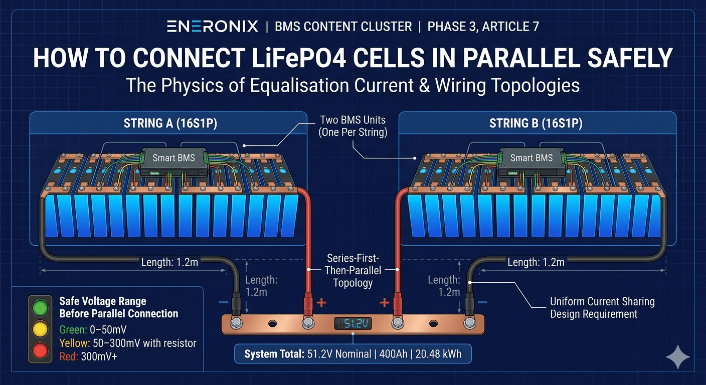
| KEY TAKEAWAY | Check the voltage of every cell before connecting anything in parallel. Under 50mV difference: connect directly. 50 to 300mV: use a 1-ohm resistor for 30 seconds then remove it. Above 300mV: charge the lower cell first. The arithmetic is not complicated and neither is the consequence of ignoring it. |
Parallel Configurations: What 2P, 3P, and 16S2P Actually Mean
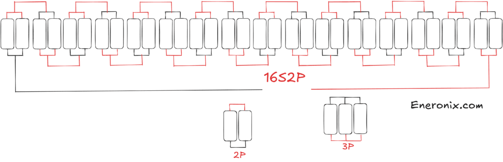
When builders talk about parallel cell configurations, they use shorthand that can be confusing if you have not seen it before. A quick glossary before the wiring topologies.
P refers to the number of cells in parallel at each position in the series string. 1P means one cell per position (single string). 2P means two cells in parallel at each position. 3P means three cells in parallel at each position.
S refers to the number of series positions. 16S means 16 cells in series, producing approximately 51.2V nominal for a 48V LiFePO4 pack.
So 16S2P means 16 positions in series, 2 cells at each position, for a total of 32 cells. The pack voltage is still 51.2V nominal (series count determines voltage). The capacity is 200Ah x 2 = 400Ah (parallel count determines capacity).
| Parameter | 16S2P Value / Note |
| Total capacity | Cell_Ah x 2 (e.g. 2 x 200Ah = 400Ah) |
| Pack voltage | Same as single cell nominal: 3.2V per parallel group |
| Pack energy (single group) | 3.2V x 400Ah = 1.28 kWh |
| In a 16S2P configuration | 51.2V x 400Ah = 20.48 kWh gross |
| Maximum discharge current | Sum of both cells’ rated discharge current (e.g. 2 x 200A = 400A at 1C for 200Ah cells) |
| BMS requirement | One BMS is required per 16S battery pack. A 16S2P cell-level configuration uses one BMS total, while a system built from two independent 16S1P packs requires two BMS units (one per pack). |
| Imbalance risk | Parallel cells self-equalise to the same voltage. Capacity differences between cells still exist. The BMS monitors one voltage per parallel group, not per individual cell. |
The energy math: a 16S2P pack with 200Ah cells has 51.2V x 400Ah = 20.48 kWh gross, approximately 16.4 kWh usable at 80% depth of discharge. For a household running 3 kWh per night, this pack provides roughly 5 nights of autonomy. For the same system with a 16S1P 200Ah pack, it is approximately 2.5 nights. The parallel string doubles the autonomy.
For the complete battery sizing calculation that determines whether you need 1P, 2P, or more strings for your specific load, our 48V lithium battery sizing guide walks through the full load audit to battery sizing process with worked examples.
Two Ways to Wire a Parallel Pack: Which Is Right for You
There are two fundamentally different approaches to wiring a parallel LiFePO4 pack, and the choice between them affects how you configure the BMS, how easy it is to diagnose problems, and how robust the system is if one cell or string fails.
| Wiring Topology | How It Works | Advantages | Disadvantages |
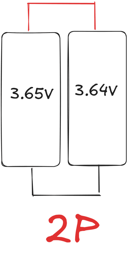
| Direct parallel before series (P first then S) | Both cells of each parallel group are connected positive-to-positive and negative-to-negative first, forming a 2P group. The 2P group is then treated as a single cell in the series string. | Simple wiring. The parallel group self-balances continuously because the cells are permanently connected positive-to-positive. Standard approach for 16S2P DIY packs. | Both cells in a parallel group must have identical specifications. If one cell fails open, the other carries all the current for that position. |
| Series first then parallel (S first then P) | Two complete 16S series strings are built independently. Each string has its own BMS. The two strings are then connected in parallel via their P+ and P- terminals on a common bus. | Each string is independently protected and monitored by its own BMS. One string can fail without the other losing protection. Easier to commission and test string by string. | More wiring complexity. Requires two complete BMS units. Parallel bus must use equal-length cables from each string to maintain equal current sharing. |
| Mixed (some groups 1P, some 2P) | Not recommended. Different parallel ratios at different positions in the series string create voltage imbalances that the BMS cannot track correctly. | Avoid. | Avoid. |
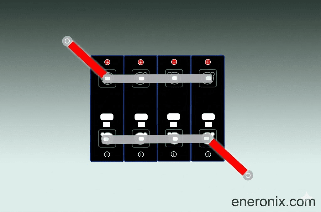
Topology 1: Parallel First, Then Series (P-then-S)
In this topology, you build each parallel group first. For a 16S2P pack, you connect Cell 1A positive to Cell 1B positive, and Cell 1A negative to Cell 1B negative. This creates a 2P group at Position 1. You repeat for all 16 positions. The 16 parallel groups are then connected in series exactly as you would connect single cells for a 16S1P pack.
The BMS sees 16 voltage nodes: one per parallel group. It cannot tell the difference between a single 400Ah cell and two 200Ah cells in parallel at each position. As far as the BMS is concerned, this is just a 16S pack with 400Ah capacity.
The advantage of P-then-S is simplicity. One BMS, one cable run to the inverter, identical commissioning procedure to a 16S1P pack. The limitation is that if one cell in a parallel group fails open, the other cell in that group now carries all the current for that position with no indication in the BMS that anything has changed.
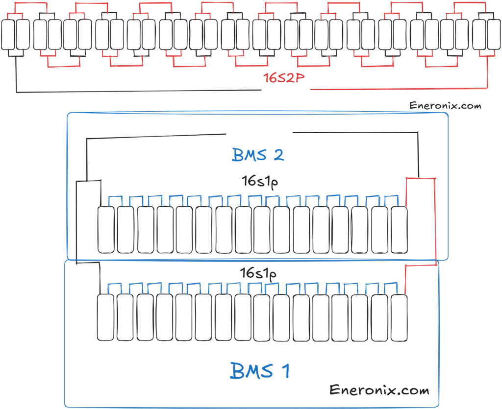
Topology 2: Series First, Then Parallel (S-then-P)
In this topology, you build two complete 16S series strings independently. Each string has its own BMS. String 1 (String A) connects to its BMS. String 2 (String B) connects to its own BMS. Both BMS units have their P+ and P- terminals connected to a shared parallel bus, which then connects to the inverter.
The BMS monitors every cell in its own string. A failing cell in String A is detected and diagnosed by String A’s BMS. String B continues to operate independently. The system provides more protection coverage than P-then-S.
The disadvantage of S-then-P is cost and complexity: two complete BMS units instead of one, more wiring, and two separate configurations to manage. But for larger systems above 400Ah where a single cell failure would be a significant event, the diagnostic advantage is worth the additional cost.
For the specific wiring of the parallel bus in an S-then-P system, the procedure is directly analogous to wiring multiple Pylontech batteries in parallel. The principles of equal cable lengths, voltage matching at connection, and BMS protocol configuration for the inverter all apply identically.
Our article on how to wire Pylontech batteries in parallel covers the parallel bus wiring, cable sizing, and inverter communication setup for a multi-string parallel system. The same procedures apply to DIY LiFePO4 parallel strings.
| KEY TAKEAWAY | For first-time parallel builders building a 16S2P pack: use P-then-S topology with a single BMS. For builders with larger packs above 400Ah who need per-string fault diagnosis: use S-then-P with one BMS per string. Both are valid. Choose based on your diagnostic requirements. |
The Equal Cable Length Rule: Why This Is Not Negotiable
In a parallel system with two or more strings, current distributes between the strings in inverse proportion to their resistance. Lower resistance strings carry more current. Higher resistance strings carry less.
In theory, the cells in each string have matching internal resistance and therefore the only variable is the cable resistance from each string to the common parallel bus. In practice, if you cut one string’s cable to 0.5 metres and the other string’s cable to 1.5 metres, you have deliberately created a 3x resistance imbalance between the strings. The short-cable string carries approximately 75% of the total load current. The long-cable string carries approximately 25%.
Over time, the string that carries more current ages faster. Its cells heat more per cycle, cycle at higher C-rate than designed, and develop higher internal resistance than the lightly loaded string. The imbalance compounds. Within 12 to 18 months, you have one string in excellent condition and one that is significantly degraded.
| Cable Configuration | Resistance Calculation | Current Distribution Effect | Practical Impact |
| String 1: 0.5m cable, String 2: 1.5m cable | 0.5m: R = 1.72e-8 x 0.5 / 50e-6 = 0.00017 ohm. 1.5m: R = 1.72e-8 x 1.5 / 50e-6 = 0.00052 ohm. | String 1 resistance is 3x lower than String 2. At 100A total load, String 1 carries approximately 75A and String 2 carries approximately 25A. | Severe. String 1 is chronically overloaded. Its BMS current sensor shows 75A while the system is designed for 50A per string. |
| String 1: 1.0m cable, String 2: 1.0m cable | Both: R = 1.72e-8 x 1.0 / 50e-6 = 0.00034 ohm. | Resistance is equal. Current distributes equally. | Balanced. 50A per string at 100A total load. |
| String 1: 1.0m cable, String 2: 1.2m cable | String 1: 0.00034 ohm. String 2: 0.00041 ohm. Difference: 17%. | String 1 carries approximately 55A, String 2 carries approximately 45A at 100A total. | Minor but present. For most applications this is acceptable. Current measurement in each BMS will confirm. |
The rule is simple: cut all parallel cable runs to the same length. Same cross-section. Same route. If String A’s P+ cable is 1.2 metres, String B’s P+ cable must also be 1.2 metres. Use cable ties to secure any excess length rather than cutting it short. A few grams of extra copper is worth it.
This principle is documented in virtually every multi-string battery system standard including the IEC 62619 safety standard for secondary lithium cells, which specifies uniform current sharing as a design requirement for parallel battery configurations. The standard is publicly referenced through the IEC webstore at iec.ch.
| FIELD TIP | When wiring a parallel system in an enclosure, measure and cut all positive cables simultaneously, then all negative cables simultaneously. This ensures they are genuinely identical in length and not just approximately identical. Mark each cable with its function before cutting so you do not mix up strings during assembly. |
The Step-by-Step Parallel Connection Procedure
With the topology chosen and cables cut to equal lengths, the actual parallel connection procedure is straightforward. The order of steps matters for safety.
For P-then-S (Cells in Parallel Before Series Assembly)
- Measure all cells individually. Record voltage for each.
- Group cells into parallel pairs. Each pair must be within 50mV of each other. If voltage differences exceed 50mV, charge the lower cell individually until the gap is under 50mV.
- For each parallel pair: connect the negative terminal of Cell A to the negative terminal of Cell B using a short bus link. Then connect the positive terminal of Cell A to the positive terminal of Cell B. The cells are now in parallel and will self-equalise to the same voltage.
- After all 16 parallel groups are assembled, proceed with series connection and BMS installation exactly as for a 16S1P pack. The parallel groups behave as single cells from the BMS perspective.
- Top balance the entire assembled pack. With two cells in each position, the top balance procedure is the same: parallel connection of all groups to a 3.65V source until current drops near zero.
For S-then-P (Complete Strings in Parallel)
- Build and commission String A as a complete 16S pack with its own BMS. Perform top balance, configure BMS thresholds, verify inverter communication.
- Build and commission String B identically. Bring String B to the same state of charge as String A. The pack terminal voltages of both strings should be within 0.2V of each other before parallel connection.
- Connect String A P- to String B P- on the common negative bus. Connect String A P+ to String B P+ on the common positive bus. If the pack voltages differ by more than 0.2V, use a pre-charge resistor (10 to 50 ohm) in the first string’s positive connection for 30 seconds before completing the direct connection.
- Connect the common bus to the inverter via the main fuse and pre-charge circuit. Configure the inverter to communicate with both BMS units if the inverter supports multi-BMS communication, or with String A as the master if only one communication link is used.
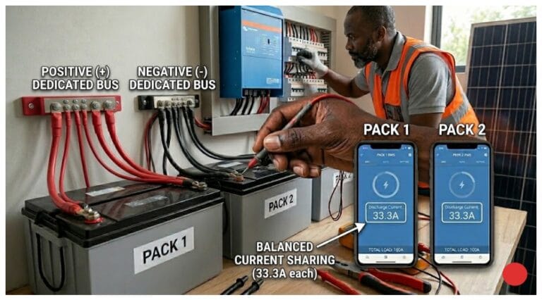
- After the parallel connection is made, verify current sharing under load by reading both BMS apps simultaneously. Equal current within 15% confirms the wiring is balanced.
BMS Configuration for Parallel Systems
When two strings share a common bus connected to one inverter, the inverter receives battery data from one BMS (or both if the inverter supports multiple BMS units). The SOC displayed on the inverter should represent the combined pack state, not just one string.
For single-master BMS communication (most common in Nigerian installations with Deye, Growatt, or Solis inverters): designate String A’s BMS as the master. The inverter communicates only with String A’s BMS. The SOC reported by String A’s BMS represents approximately half the total system energy, but because both strings are at the same voltage (they are in parallel), the SOC calculation is approximately correct for the combined system.
String B’s BMS operates independently, protecting String B’s cells. Its data is only accessible via the Bluetooth app. This is adequate for most installations. For commercial installations where precise aggregate SOC reporting is required, check whether the inverter supports multi-BMS aggregation (some Victron and newer Deye firmware versions support this).
The specific protocol configuration for multi-string systems with Deye and Growatt inverters is covered in our article on inverter-battery communication protocols in modern solar systems. The parallel string communication architecture is one of the advanced configurations documented there.
Five Parallel Connection Mistakes and Their Consequences
| MISTAKE 1 | Connecting cells at large voltage differences directly in parallel without a limiting resistor. A 500mV voltage difference between two 200Ah cells creates an equalisation current of approximately 500 to 1,000 amps for a few seconds. This spike heats the cells and busbars rapidly, can cause lithium plating on the receiving cell’s anode, and stresses the busbar connections. Some builders never notice because the cells survive. Over time the affected cells show higher internal resistance and faster capacity loss from the stress event. Always measure voltages before connecting. |
| MISTAKE 2 | Cutting parallel bus cables to unequal lengths and expecting it not to matter. A 3x resistance difference between cable paths creates a 3x current imbalance between strings. This is not a minor performance issue. At 100A total system load, the short-cable string carries 75A and the long-cable string carries 25A. The short-cable string’s BMS is running near its thermal limit while the long-cable string is barely working. After 18 months, the pack has aged at two different rates and the system delivers less capacity than expected. |
| MISTAKE 3 | Using one BMS for a multi-string S-then-P system by connecting both strings to the same BMS P+ terminal. Without individual BMS protection on each string, cells in the second string are unmonitored. A weak cell in the unmonitored string will hit UVP during discharge or OVP during charge with no protection responding. The system continues to run. The weak cell is progressively damaged until it fails. You discover it only when pack capacity has dropped significantly. |
| MISTAKE 4 | Mixing cells from different production batches or different ages in the same parallel group. A 200Ah new cell and a 180Ah older cell in parallel at the same position carry unequal current because their internal resistances differ. The lower-resistance new cell carries more current. Over time the load imbalance accelerates capacity divergence. A pack assembled with mixed cells in parallel groups will show increasing imbalance within 6 to 12 months regardless of how well the BMS balances the series string. |
| MISTAKE 5 | Not verifying current sharing after installation. Connecting two strings in parallel and assuming they are sharing equally is not safe practice. One connection that is slightly loose, one cable that is slightly longer, one cell internal resistance that is slightly higher, all of these create current imbalance that is invisible without checking. Open both BMS apps under load after commissioning and verify the current is within 15% between strings. This takes 3 minutes and catches problems before 18 months of uneven cycling creates them. |
For the diagnostic procedure to check whether unequal current sharing has already caused BMS degradation in an existing parallel system, see our article on signs of a failing BMS. The current sensor drift diagnostic in that article specifically addresses the scenario where one string’s BMS reads differently from the expected current share.
One Final Thought on Parallel Cells
Parallel connections multiply capacity. They also multiply the number of things that can go wrong if the wiring is not done carefully. A 16S1P pack has 16 cells to worry about. A 16S2P pack has 32. A 16S3P pack has 48.
The builders who get the best long-term performance from parallel packs are the ones who are most systematic about matching cells before assembly, cutting cables to equal lengths, verifying current sharing after commissioning, and checking the BMS apps at the 30-day and 6-month marks rather than assuming everything is fine.
It is not difficult work. But it requires actual attention rather than assumption. Parallel packs reward careful builders and punish sloppy ones, silently, over 18 months.
Frequently Asked Questions
Can I connect LiFePO4 cells of different capacities in parallel?
Technically yes, but it is not recommended for daily-cycling solar storage. When cells of different capacities are connected in parallel, the higher-capacity cell will supply more current during discharge and accept more current during charge, even though they are at the same voltage. The internal resistance ratio determines the current split. Over time, the cells age at different rates because of the unequal loading. For a permanent solar storage pack, use cells from the same batch with matched capacities within 2% of each other. Different-capacity parallel connections are acceptable only for temporary use or for packs with very low cycling frequency.
What voltage difference is safe before connecting cells in parallel?
For cells at 50mV or less difference, direct parallel connection is generally safe. Even a 50mV voltage difference can produce a brief equalisation current of tens to over one hundred amps because large LiFePO4 cells have extremely low internal resistance. The duration is typically very short, which is why small voltage differences are generally acceptable. For best practice, bring cells within 50mV before connecting them in parallel. For differences of 100mV to 300mV, use a current-limiting resistor before making the final connection. For differences above 300mV, bring the cells closer in voltage before connecting them in parallel.
Do I need a separate BMS for each parallel string?
For the series-first-then-parallel topology (two complete 16S strings joined at their P+ and P- outputs), yes, each string needs its own BMS. Each BMS monitors and protects 16 cells. Without a BMS on each string, cells in the unmonitored strings can be overcharged, deep-discharged, or develop undetected faults. For the parallel-first-then-series topology (cells connected in 2P groups before series assembly), a single BMS monitoring 16 voltage nodes (one per parallel group) is adequate. The BMS sees the parallel group as a single cell.
What is the best way to wire two parallel battery packs?
Use the series-first-then-parallel topology with one BMS per 16S string. Connect the two strings to a common parallel bus using equal-length cables of the same cross-section from each string to the bus. Equal cable lengths ensure equal resistance and therefore equal current sharing between strings. The common bus then connects to the inverter via the main fuse and pre-charge circuit. Verify current sharing by checking each BMS app under load: both should show approximately equal current.
Why do batteries heat up when connected in parallel?
Heat during parallel connection is caused by equalisation current flowing between the cells to equalise their voltages. If cells are at different voltages when connected, current flows from the higher-voltage cell to the lower-voltage cell until both reach the same voltage. The heat generated is I2 x R, where I is the equalisation current and R is the combined internal resistance.
For cells at similar voltages (under 50mV difference), equalisation current is brief and generally well tolerated by healthy LiFePO4 cells. As voltage differences increase, both the peak equalisation current and the resulting heat increase significantly. Always bring cells as close in voltage as practical before connecting them in parallel. For cells at large voltage differences (over 300mV), the current can be tens of amps and the heat is significant. Always bring cells to within 50mV before connecting in parallel.
Can I mix old and new cells in a parallel pack?
No. Mixing old and new cells in parallel creates an immediate and ongoing problem. Old cells have higher internal resistance and lower capacity than new cells. In parallel, the new low-resistance cells carry more current than the old high-resistance cells during both charge and discharge. The old cells are underutilised while the new cells are overworked. The pack as a whole delivers less capacity than the new cells alone would provide because the old cells drag the parallel group’s average performance down. Always use cells of similar age, similar capacity, and similar internal resistance in any parallel group.
How do I check if my parallel packs are sharing current equally?
Open both BMS apps simultaneously while the system is under a representative load. Read the discharge current reported by each BMS. In a correctly wired two-string parallel system with equal cable lengths, both BMS units should report approximately equal current within 10 to 15% of each other. If one string is showing significantly higher current than the other (for example, 80A vs 20A when both should be around 50A), the cable lengths are unequal or there is a difference in cable cross-section or connection quality that is creating unequal resistance between the two paths. Investigate and correct the physical wiring.
External References
- IEC 62619 — Safety requirements for secondary lithium cells and batteries: parallel configuration current sharing requirements
- IEEE 1625 — Standard for Rechargeable Batteries for Multi-Cell Mobile Computing Devices: parallel cell considerations: standards.
- Battery University — Parallel battery configurations: current sharing and imbalance effects

I am Engr. Ubokobong Ekpenyong, a solar specialist and lithium battery systems engineer with over five years of hands-on experience designing, assembling, and commissioning off-grid solar and energy storage systems. My work focuses on lithium battery pack architecture, BMS configuration, and system reliability in off-grid and high-demand environments.