Signs of a Failing BMS (And How to Prevent Damage)
7 signs of a failing BMS is explained with real field scenarios, root cause analysis, and step-by-step diagnostic procedures. Learn how to catch BMS failure before it destroys your battery pack.
There is a conversation I have had many times, in different forms, with different people, but it always sounds roughly the same.
The customer says the battery is dying. The installer agrees and is already thinking about replacement cells. But when you sit down with the BMS app and actually look at what is happening inside the pack, the cells are fine. All 16 of them are sitting at healthy voltages, similar capacities, low internal resistance. The pack is not dying.
The BMS is dying. And because nobody checked, the cells have been operating outside their safe parameters for weeks while the failing BMS continued to report incorrect data to the inverter.
BMS failure is misdiagnosed as battery failure more often than any other fault in the Nigerian solar storage market. The symptoms look the same from the outside: reduced runtime, unexpected disconnections, incorrect SOC readings, inconsistent performance. The diagnosis is different and the solution is different. Replacing cells when the BMS is the problem is expensive. Missing BMS failure until the cells are damaged is even more expensive.
This article gives you the seven signs of a failing BMS, the engineering explanation behind each one, and a step-by-step diagnostic protocol for confirming whether you are looking at a BMS problem, a cell problem, or something else entirely.
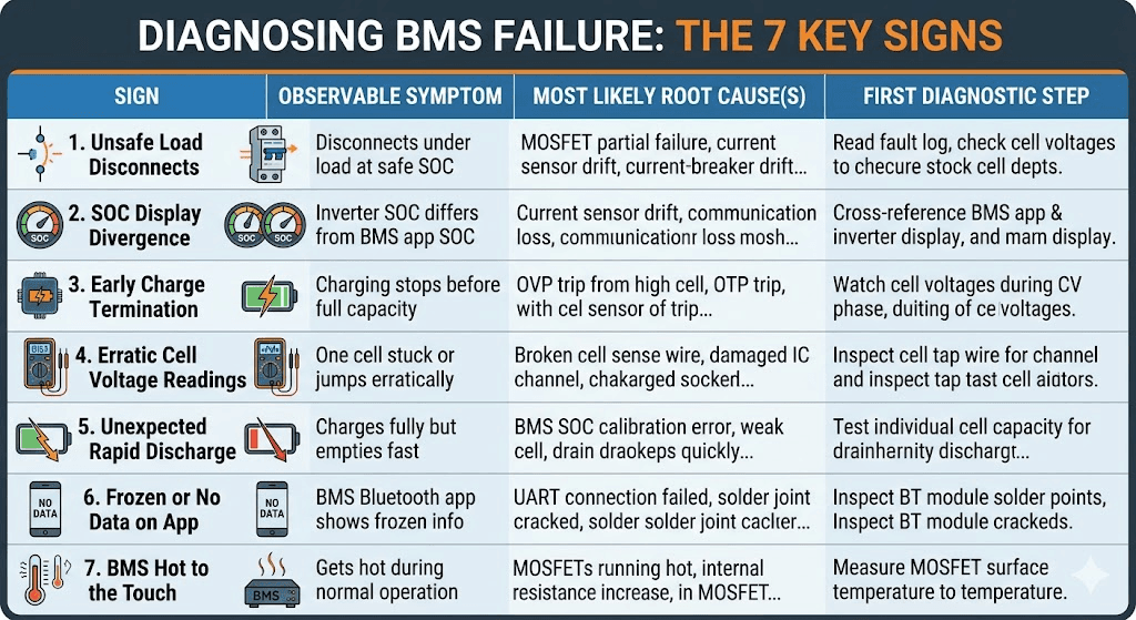
Here is the complete reference table first, so you have it for quick diagnosis. Each sign is then explained in depth below.
Sign
Observable Symptom
Most Likely Root Cause(s)
First Diagnostic Step
1
Battery disconnects under load at a state of charge that should be safe
MOSFET partial failure, current sensor drift, OCP threshold misconfiguration, or weak cell triggering UVP
Read BMS fault log. Check cell voltages at time of disconnect. Measure actual pack current with clamp meter.
2
Inverter SOC display diverges significantly from BMS app SOC
Current sensor drift causing coulomb counting errors. BMS-to-inverter communication loss. SOC calibration drift.
Cross-reference BMS app SOC against inverter display. If they diverge over 5%, check communication link and recalibrate BMS SOC.
3
Charging terminates early without reaching full capacity
OVP trip from one high cell, OTP trip from elevated temperature, charge MOSFET partial failure, inverter communication sending incorrect CVL.
Watch individual cell voltages during CV phase. Identify which cell triggers early termination. Check BMS app for OVP or OTP events.
4
One cell voltage reads stuck at a fixed value or jumps erratically
Broken or high-resistance cell sense wire. Damaged cell monitoring IC channel. Loose balance wire connection.
Inspect the cell tap wire for that channel physically. Check resistance with a multimeter. Replace the sense wire if resistance is high.
5
Battery charges to full but discharges faster than expected
BMS SOC calibration error (showing full when not truly full). Weak cell limiting accessible capacity. MOSFET on-resistance increase from degradation.
Test individual cell capacity. Check BMS current sensor accuracy by comparing measured pack current against inverter reported current.
6
BMS Bluetooth app connects but shows no data or frozen data
UART connection between BMS MCU and Bluetooth module failed. Thermal cycling cracked a solder joint on the Bluetooth PCB interface.
Inspect Bluetooth module solder points if board is accessible. In most cases, BMS hardware replacement is required.
7
BMS gets hot to the touch during normal operation
MOSFETs running above rated thermal point from undersizing or inadequate enclosure ventilation. Internal resistance has increased from degradation.
Measure MOSFET surface temperature with IR thermometer. Above 65 degC surface during normal load indicates a problem. Improve ventilation or replace BMS with correctly rated unit.
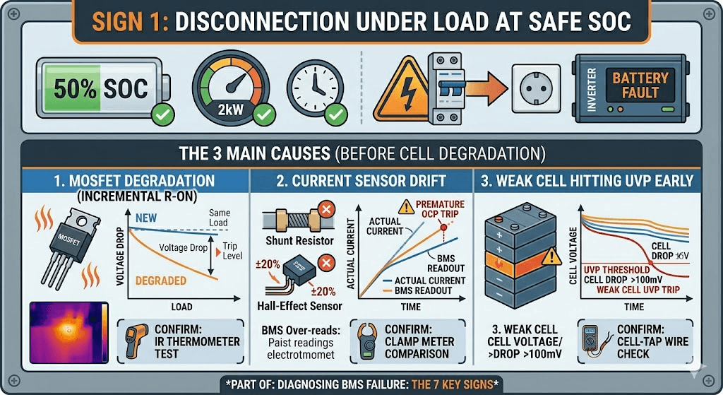
Sign 1: The Battery Disconnects Under Load at a Seemingly Safe SOC
The inverter is running at 50% SOC. Loads are normal. No abnormal peaks. And then the battery disconnects. The inverter shows a battery fault. You reconnect, and within a few hours it happens again.
The instinct is to blame the cells. But there are three BMS hardware problems that cause exactly this symptom before any cell has degraded at all.
The MOSFET Is Degrading
A MOSFET that has been running near its thermal limit for an extended period develops a slowly increasing on-resistance. As resistance rises, the voltage drop across the MOSFET at a given current also rises. The BMS firmware monitors this voltage and uses it as part of its protection logic.
When the MOSFET on-resistance has increased enough, a normal operating current creates a voltage drop that the BMS interprets as an overcurrent event. The BMS trips OCP even though the actual current is within the rated limit. From the outside, it looks like the battery is cutting out for no reason. From inside the BMS, the MOSFET is telling the protection logic that it is being pushed harder than it actually is.
How to confirm: measure the MOSFET surface temperature with an IR thermometer during normal load. A MOSFET running hot during what should be routine operation is telling you its resistance has increased. Cross-reference the BMS app current reading against a clamp meter measurement on the battery cable. If the BMS is reading higher current than the clamp meter is measuring, the current sensing path has drifted.
The Current Sensor Has Drifted
The BMS current sensor uses either a shunt resistor or Hall-effect sensor to measure discharge current. Both can drift over time due to temperature cycling, component aging, or mechanical stress. A drifted sensor that reads 15 to 20% higher than actual current will cause OCP trips at loads that should be well within the rated limit.
This is one of the most insidious BMS failure modes because the protection function is technically working correctly. The BMS is tripping OCP based on what it believes is the current. The fault is that what it believes is wrong.
SOC error from current sensor drift is covered in detail in our article on SOC drift: why your BMS and inverter disagree. The same drift that causes SOC errors also causes premature OCP trips when the sensor over-reads current.
A Weak Cell Is Hitting UVP Early
This is a cell problem rather than a pure BMS hardware problem, but it presents identically from the customer’s perspective and the BMS is the tool you use to diagnose it. If one cell in the pack has significantly less capacity than the others, it hits the UVP threshold during discharge while the pack as a whole still has 30 to 40% of its nominal capacity remaining.
The BMS is working correctly: it disconnected when a cell reached the danger threshold. But the customer experience is a battery that cuts out at 50% SOC with no warning.
Open the BMS app during a discharge cycle and watch individual cell voltages. The cell that is dropping fastest is the culprit. If it is 100mV or more below its neighbours during mid-discharge, it needs investigation.
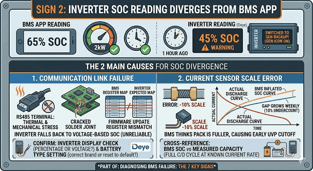
Sign 2: The Inverter SOC Reading Diverges From the BMS App
You have a BMS app showing 65% SOC. The Deye inverter is showing 45% SOC. The system switched to generator backup an hour ago based on the inverter reading. But the cells are genuinely at 65%.
When the BMS app and the inverter disagree significantly on SOC, one of three things has happened.
The Communication Link Has Failed
The RS485 cable is physically connected but the inverter is no longer receiving BMS data. Maybe a connector worked loose. Maybe a thermal cycle cracked a solder joint on the RS485 terminal block. Maybe the BMS firmware updated and changed a register that the inverter expects at a different address.
The inverter, receiving nothing from the BMS, falls back to its own voltage-based SOC estimation. For LiFePO4, this is unreliable across most of the discharge range because the voltage curve is flat. The inverter guesses wrong and acts on the wrong guess.
How to confirm: check whether the inverter display shows SOC as a percentage or as a voltage. If it shows voltage, communication is definitely lost. Also check whether the inverter’s battery type setting still shows the correct BMS brand, or whether a firmware update reset it to a default.
The Current Sensor Has a Scale Error
If the BMS current sensor reads 10% low consistently, the coulomb counting will show the pack as fuller than it actually is. After a week of daily cycling at 10% undercount, the BMS thinks the pack has 10% more charge than it really has at any given moment.
The inverter, if it is receiving BMS SOC data, will display the inflated SOC from the BMS. But the pack will reach its UVP cutoff earlier than the BMS predicted. The inverter will see an unexpected battery disconnect at what should have been a safe SOC.
This is why the annual cross-reference check matters: compare BMS reported SOC against measured capacity annually by doing a full charge and full discharge at a known current rate.
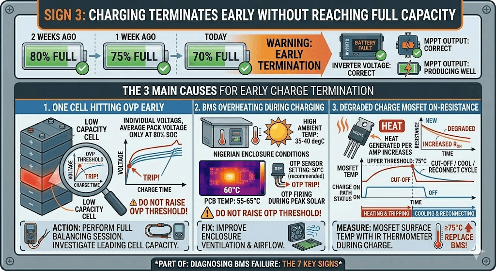
Sign 3: Charging Terminates Earlier Than Expected
The pack should charge to full each day. But for the past two weeks, charging has been stopping at 80%, then 75%, then 70% full. The inverter charge voltage is set correctly. The MPPT is producing well. Something is cutting the charge short.
There are four BMS-related causes for early charge termination.
One Cell Is Reaching OVP Before the Pack Is Full
The most common cause. One cell with lower capacity charges faster than its neighbours and reaches the OVP threshold while the rest of the pack is only at 80 to 85% SOC. The BMS correctly trips OVP to protect that cell. From the customer’s perspective, the pack is not charging fully.
The solution is not to raise the OVP threshold. The solution is to run a full balancing session and investigate whether the leading cell has genuinely lower capacity than its neighbours. If the balancer cannot correct the divergence within a few days of normal cycling, the leading cell may need individual capacity testing.
The BMS Is Overheating During Charging
In Nigerian enclosure conditions during midday charging, the BMS PCB temperature can climb to 55 to 65 degC. If the OTP charge threshold is set to 50 degC (as recommended for Nigerian conditions), OTP will fire during peak solar hours and cut charging.
This is the BMS working correctly, but it is also telling you something important: the enclosure ventilation is inadequate. The fix is not to raise the OTP threshold. The fix is to improve airflow across the BMS board.
The Charge MOSFET Has Increased On-Resistance
A degraded charge MOSFET generates more heat per amp of charge current than a healthy one. As the MOSFET heats up under charge current, the BMS thermal protection triggers. The charge path is cut. After cooling, the BMS reconnects. The cycle repeats. From the outside, charging appears erratic or incomplete.
Measure MOSFET surface temperature during the charge cycle with an IR thermometer. A charge MOSFET reaching 75 degC or above during normal charge current is running too hot and should prompt BMS replacement before it fails completely.
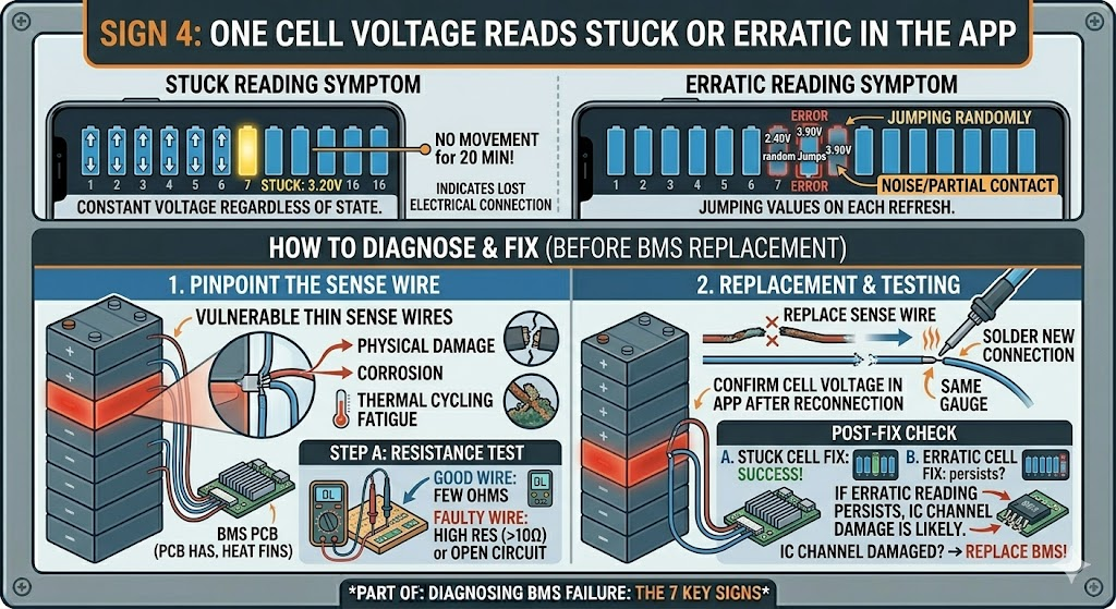
Sign 4: One Cell Voltage Reads Stuck or Erratic in the App
You open the BMS app and 15 of the 16 cell bars are moving normally as the pack charges. One bar is stuck at 3.20V and has not moved in the past 20 minutes. Or one bar is jumping between 2.40V and 3.90V randomly while all the others are stable.
A cell that reads stuck at a constant voltage regardless of charge or discharge state has lost electrical connection to the BMS monitoring circuit. The voltage you are seeing is the last voltage that was properly measured before the connection broke, or the default value the BMS assigns to a disconnected channel.
A cell that reads erratically, jumping to different values on each refresh, has a high-resistance or intermittent connection on the cell sense wire. The BMS is getting noise or partial contact on that monitoring channel.
How to Diagnose
The cell sense wires are the thin wires that connect each cell junction to the BMS PCB. They carry only monitoring voltage, no power current, so they use small-gauge wire that is vulnerable to physical damage, corrosion, or thermal cycling fatigue.
With the pack disconnected from all loads and chargers, measure the resistance of the sense wire for the affected cell channel using a multimeter set to resistance. The wire should read a few ohms at most. A reading above 10 ohms indicates high resistance. A reading of infinite resistance (open circuit) means the wire is broken.
In most cases, the sense wire can be replaced without replacing the BMS. Source the same gauge wire, solder a new connection at both ends, and confirm the cell voltage reads correctly in the app after reconnection. If the erratic readings persist after sense wire replacement, the cell monitoring IC channel on the BMS PCB itself may have been damaged by the intermittent connection.
FIELD OBSERVATION
In generator rooms where the battery enclosure sits on or near a running generator, vibration fatigue on cell sense wire solder joints is a frequent cause of erratic cell voltage readings. The thin sense wires are particularly vulnerable because they have low mass and are soldered to a relatively large PCB that vibrates with the structure. If an installation is in a generator room, inspect sense wire solder joints annually and consider using silicone wire instead of PVC for its better flex fatigue resistance.
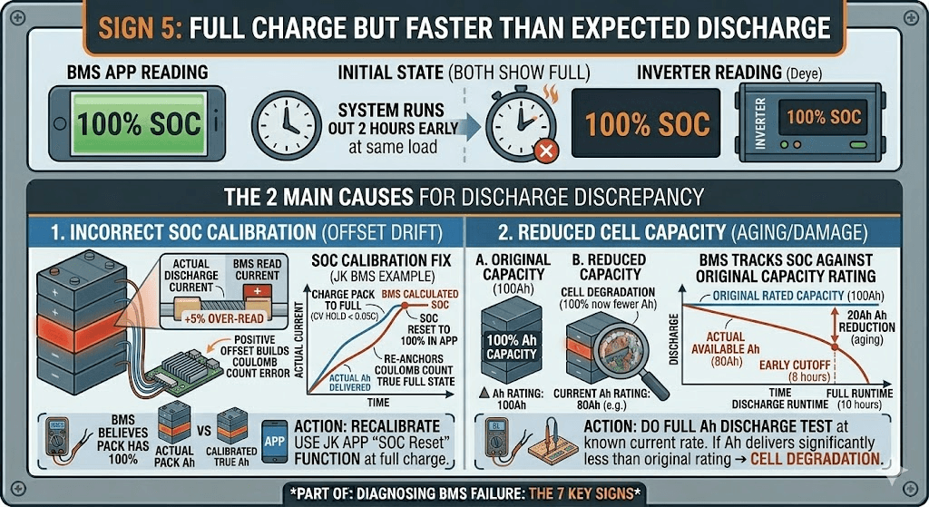
Sign 5: Full Charge But Faster Than Expected Discharge
The BMS app shows the pack charged to 100%. The inverter shows 100%. But the system is running out of charge two hours earlier than it should at the same load.
There are two BMS failure modes that produce this symptom.
The BMS SOC Is Calibrated Incorrectly
If the BMS current sensor has a positive offset (reads slightly more discharge current than actual), the coulomb counting will accumulate an error over time, showing the pack as emptier than it actually is. After a period of running with the offset, the BMS is calibrated against the wrong baseline. When it shows 100% SOC, the pack may only be at 85 to 90% of true full charge.
Recalibrate the BMS SOC. On the JK BMS, this is done by charging the pack to full (hold at CV until charge current drops below 0.05C) and then using the SOC calibration function in the app to reset to 100%. This re-anchors the coulomb counting to a confirmed full charge state.
Cell Capacity Has Reduced But SOC Is Still Tracking Against Original Capacity
If the cells have lost capacity through aging or damage, the BMS may still be tracking SOC against the original rated capacity. The pack shows 100% SOC but that 100% now represents fewer Ah than it did at installation.
This is technically cell degradation rather than BMS failure, but the BMS is the tool that reveals it. Do a full discharge at a known current rate and measure total Ah delivered. If it is significantly less than the original rated capacity, the cells have degraded. If it matches the rated capacity, the BMS SOC calibration is the issue.
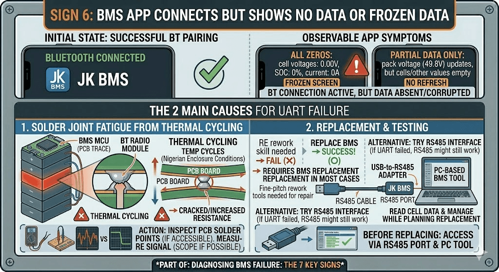
Sign 6: The BMS App Connects But Shows No Data or Frozen Data
You pair the Bluetooth on your phone. The JK BMS app connects successfully. But the screen is frozen on the last reading, or shows all zeros, or refreshes only the pack voltage and nothing else.
When the Bluetooth connection is live but the data is wrong or absent, the fault is typically on the UART connection between the BMS microcontroller and the Bluetooth radio module. These are two separate components on the BMS PCB connected by a short UART serial link. If that link fails, the Bluetooth module continues advertising and accepting connections (because it is powered and functional) but has no data to display because the MCU is not sending any.
What Causes This
The UART connection is a PCB trace and a few solder joints. In thermally stressed environments where the PCB expands and contracts with temperature cycles, solder joint fatigue is the most common cause of failure. The joint does not completely break, but resistance increases to the point where the UART signal is too weak to decode reliably. The Bluetooth module receives corrupted data and displays nothing.
In most cases this requires BMS replacement rather than repair, unless you have the tools and skills for fine-pitch PCB solder rework. Before replacing, try the alternative: some JK BMS units can be accessed via the RS485 port directly using a USB-to-RS485 adapter and a PC-based BMS configuration tool. If the RS485 interface is working correctly, you can still read cell data and manage the BMS through that path while planning the replacement.
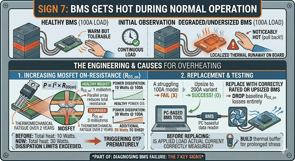
Sign 7: The BMS Gets Hot During Normal Operation
You check the battery enclosure and the BMS board is uncomfortably hot. Not warm from normal operation but noticeably hot. You hold your hand near it and pull back.
A BMS that is running significantly hotter than ambient during normal load is a BMS that is either undersized for the actual current or has degraded MOSFETs with increased on-resistance, or both.
The Engineering Behind BMS Heating
Power dissipation in the BMS MOSFETs is governed by P = I squared times R_DS_on. Where I is the current flowing through the MOSFET and R_DS_on is its on-resistance. At rated specifications, a healthy MOSFET has a very low R_DS_on, typically 0.5 to 2 milliohms per MOSFET, and the parallel arrangement of multiple MOSFETs in a BMS reduces this further. Total power dissipation should be modest.
When the MOSFET has degraded, R_DS_on increases. Maybe it was 1 milliohm at installation and is now 3 milliohms after two years of thermal stress. At 100A discharge current, 1 milliohm produces 10 watts of heat. 3 milliohms produces 30 watts. The BMS board is now dissipating 20 additional watts that it was not designed to handle thermally, and the temperature rises accordingly.
Measure MOSFET surface temperature with an IR thermometer during a representative load cycle. A healthy BMS running at 100A should show MOSFET temperatures no more than 15 to 25 degC above ambient in a ventilated enclosure. If MOSFET temperature is 40 to 50 degC above ambient during normal operation, the MOSFETs are running in a degraded state.
ACTION THRESHOLD
If the BMS MOSFET surface temperature exceeds 75 degC during normal load operation, schedule immediate BMS replacement. At 80 degC MOSFET surface temperature, the component is operating beyond its reliability zone for the junction temperature inside. At 90 degC surface temperature, complete MOSFET failure is imminent. Do not continue operating a battery system with a BMS showing these temperatures.
BMS MOSFET Failure Modes: Understanding What Is Actually Breaking
The MOSFET is the most failure-prone component in a BMS deployed in Nigerian conditions. Understanding how MOSFETs fail explains why the symptoms look the way they do and what the correct response is for each failure mode.
MOSFET Failure Mode
Observable Symptom
Typical Cause in Nigerian Solar Installations
Impact on Protection Integrity
Open failure (stuck open)
MOSFET cannot conduct current in either direction. Pack appears completely dead: no charge or discharge possible.
Hard overcurrent event (short circuit beyond SCP rating), catastrophic thermal runaway in the MOSFET junction, gate driver IC failure that leaves the gate permanently at drive-off voltage.
Complete. Pack is isolated from external circuit. System inoperable.
Short failure (stuck closed)
MOSFET cannot open on BMS command. Protection cannot disconnect the pack. BMS may show fault state but circuit remains connected.
Progressive thermal degradation reducing the drain-source breakdown voltage below the circuit voltage. Repeated overcurrent events that each slightly reduce breakdown margin.
Catastrophic. OVP, UVP, OCP, and SCP protection are all compromised because the switch cannot open. Cells are unprotected even when the BMS believes it has disconnected them.
Increased on-resistance
MOSFET conducts but with higher resistance than rated. Increased heat dissipation under load. Reduced apparent pack capacity due to increased voltage drop at high current.
Sustained thermal stress cycling. Operating near maximum rated current for extended periods. Natural component aging accelerated by heat.
Partial and progressive. System continues to function but efficiency decreases and thermal stress on the BMS increases. Eventually leads to either open or short failure.
Slow switching (degraded gate)
MOSFET switches incompletely or slowly. Short circuit response time increases. During switching transitions, the MOSFET passes through a high-resistance high-power zone longer than designed.
Gate oxide degradation from voltage stress. Gate driver IC output impedance increase. Gate capacitor damage from repeated high-current switching events.
Partial. Most protection functions still work, but SCP response time increases. For LiFePO4 this is less critical; for NMC or NCA it represents a safety concern.
The engineering context for why MOSFET sizing matters so much in Nigerian conditions is in our article on how to size a BMS correctly. The thermal derating calculation in that article directly explains why Nigerian installations need more BMS current headroom than global standards specify.
Current Sensor Failure: The Silent SOC Killer
The current sensor is the BMS component that most directly affects day-to-day system performance without appearing to be faulty. A failed MOSFET produces obvious symptoms: the battery disconnects. A drifted current sensor produces subtle symptoms that accumulate over weeks: SOC readings that slowly diverge from reality, systems that run out of charge earlier than expected, inverters that switch to generator backup at the wrong time.
Current Sensor Failure Type
What You See
Effect on SOC Accuracy and System Behaviour
Zero offset drift
BMS reports current flowing when the pack is at rest (not charging or discharging). Even at open circuit, the BMS shows a small non-zero current reading.
This small phantom current integrates into the SOC calculation continuously. Over weeks, the SOC reading drifts away from reality. The BMS may show 80% SOC when the pack is genuinely at 60%.
Scale factor error
BMS current reading is consistently higher or lower than the actual current by a fixed percentage. The inverter and a clamp meter show different values.
SOC calculation is systematically wrong by the scale factor error. A 10% scale factor error means the BMS thinks it has discharged 10% more or less energy than it actually has on every cycle. Over months, this produces a large cumulative SOC error.
Temperature coefficient error
BMS current accuracy changes with temperature. Current readings are accurate in the morning and increasingly wrong in the afternoon as the BMS heats up.
SOC accuracy varies throughout the day. Night-time SOC readings may be reliable while peak-heat afternoon readings are significantly off. The inverter makes different decisions at different times of day based on inaccurate data.
Complete failure
BMS shows zero current regardless of actual load or charge state. SOC may be stuck at one value or jump randomly.
Without current measurement, coulomb counting cannot function. The BMS falls back to voltage-based SOC estimation, which for LiFePO4 is unreliable across most of the discharge range. All current-dependent protection functions (OCP, DCL) also lose their data source.
FIELD TIP
The fastest way to check for current sensor drift in the field is to compare three numbers simultaneously: the BMS app current reading, the inverter’s reported battery current, and a clamp meter measurement on the main battery cable. All three should agree within 3 to 5%. If the BMS app reads significantly different from both the inverter and the clamp meter, the BMS current sensor has drifted. If only the inverter disagrees, the communication link is the problem, not the sensor.
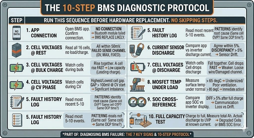
The 10-Step BMS Diagnostic Protocol
When a customer reports any of the seven signs above, this is the diagnostic sequence I run before drawing any conclusions. Do not skip steps. Do not replace hardware before completing the diagnostic. The most expensive mistake in BMS troubleshooting is replacing the wrong component.
Step
Action
What to Look For and What It Means
1
Open BMS Bluetooth app. Confirm connection.
If app fails to connect: Bluetooth module failed. BMS hardware replacement likely required.
2
Read all 16 cell voltages with pack at rest (no charge or load).
All cells should be within 50mV of each other. A cell reading 0V, max voltage, or a fixed value unrelated to the others indicates a failed sense channel.
3
Start a charge cycle. Watch cell voltages during bulk charge.
All cells should rise together at similar rates. A cell that rises significantly faster than others has lower capacity and is leading the charge. A cell stuck at a fixed value while others rise has a failed sense wire.
4
Watch cell voltages during CV phase.
Look for which cell reaches the OVP threshold first. Note the voltage gap between the highest and lowest cell. Over 100mV gap at CV phase start indicates significant imbalance.
5
Read BMS fault history log.
Note the most recent 5-10 fault events. Are they all OVP on the same cell? All OTP? All OCP at a similar time of day? Patterns in the log identify the root cause.
6
Start a discharge cycle. Watch current reading.
Compare BMS app current reading against inverter reported discharge current. Should agree within 5%. A large discrepancy indicates current sensor drift.
7
Watch cell voltages during discharge.
All cells should fall together. A cell that drops faster than others is weaker. A cell that reads erratically during discharge has a loose sense wire or damaged monitoring channel.
8
Measure MOSFET temperature under load with IR thermometer.
MOSFET surface temperature above 65 degC during normal load indicates undersizing or inadequate ventilation. Above 80 degC is immediate action territory.
9
Cross-reference inverter SOC display against BMS app SOC.
Difference over 5% after a full charge cycle indicates either communication loss or current sensor calibration drift. Investigate which.
10
Perform a full capacity test if previous steps are inconclusive.
Charge to full, discharge to UVP cutoff at a known current, measure the total Ah delivered. Compare against rated capacity. Actual capacity below 80% of rated indicates either significant cell degradation or BMS SOC miscalibration.
How to Prevent BMS Failure: Six Practices That Extend BMS Life
Most of the BMS failures I encounter in the field were preventable. Not in a theoretical way but in a practical way. Wrong current rating, no ventilation, no communication cable connected. The same three mistakes over and over.
Here is the complete prevention framework.
Prevention Practice
How to Implement It
Why It Extends BMS Life
Correct current sizing
Size BMS at 125% of max inverter current demand, plus 15% thermal derating for Nigerian conditions. For a 5kVA/48V system: 200A BMS minimum.
Eliminates the sustained thermal stress that is the primary cause of MOSFET degradation in Nigerian field installations.
Enclosure ventilation
Ensure airflow across the BMS board. MOSFET surface temperature should not exceed 55 degC during peak load. Add a forced-air fan if passive ventilation is insufficient.
Keeps MOSFETs within their thermal rating, extends electrolytic capacitor life, and prevents OTP trips that stress the system.
Communication cable connected
Always connect and configure the RS485 or CAN communication cable. A communicating BMS uses CVL and CCL to moderate inverter behaviour before hard trips become necessary.
Reduces MOSFET switching frequency and amplitude. A BMS that rarely needs to hard-trip its MOSFETs experiences far less switching stress than one that is constantly in hard-protection mode.
Active balancing specified
Use a BMS with active balancing for any pack above 100Ah in daily service. Prevents the cell imbalance that leads to repeated OVP and UVP trips.
A pack with well-matched cells does not stress the BMS protection circuits. Reduced trip frequency is directly correlated with longer BMS hardware life.
Annual app health check
Once per year, open the BMS app on every installation. Read cell voltages, check fault log, verify SOC accuracy, confirm communication with inverter.
Catches early-stage failures (growing imbalance, drifting current sensor, OTP trips) before they escalate to hardware failure or cell damage.
Protect from physical shock
Mount the BMS securely on a vibration-dampened surface. In generator rooms especially, structural vibration causes solder joint fatigue over time.
Prevents intermittent connections on cell sense wires, thermistor connections, and Bluetooth module solder joints that are the most common connection failure mode.
For the full lifespan extension framework covering both BMS and cell health, our article on how to increase lithium battery lifespan covers the operational practices that keep a well-specified system performing well for 10 years or more.
BMS Failure vs Cell Failure: How to Tell the Difference
The question that comes up most often at the end of a BMS diagnostic is: is this a BMS problem or a cell problem? The answer matters because the solutions are completely different and the cost is completely different.
Here is the diagnostic logic I use:
Test cells individually before concluding they have failed
Disconnect the BMS, remove cells from the pack, and test each one individually with a cell capacity tester at 0.2C discharge rate. If cells test at 90% or more of their rated capacity, the cells are healthy and the problem is in the BMS or system configuration.
Check cell voltages at rest before assuming imbalance is the BMS failing
Leave the pack at rest (no charge or discharge) for 4 to 8 hours. Read cell voltages. On a healthy balanced pack, all cells should be within 30 to 50mV of each other. If one cell is significantly below the others after a rest period, that cell has higher self-discharge and may be defective at the cell level. This is cell failure, not BMS failure.
The critical distinguishing test
If the BMS app shows erratic or impossible cell voltage readings (negative voltage, voltages above 4.5V on LiFePO4, voltages that do not change during charge), and physically measuring the cell terminals with a multimeter shows normal voltages that contradict the BMS display, the BMS monitoring circuit has failed. The cells are fine and the BMS is giving you false data.
If the BMS app shows accurate cell voltages that confirm one cell is significantly degraded compared to its neighbours, the problem is the cell. The BMS is working correctly and is showing you exactly what is happening.
The complete framework for distinguishing BMS failure from battery failure is also covered in our article on lithium battery problems: real causes and prevention. It covers the most common misdiagnoses and the diagnostic steps that avoid expensive mistakes.
Frequently Asked Questions
How do I know if my BMS is failing?
The clearest signs of a failing BMS are: the battery disconnects under load at a state of charge that should be safe, the inverter displays SOC readings that do not match the BMS app, charging terminates early without reaching full capacity, one or more cell voltages show erratic or stuck readings that do not change during charge and discharge, and the BMS app either fails to connect or shows cell data that contradicts the physical state of the pack. Open the BMS app, pull the fault log, and read the cell voltages in real time during a charge and discharge cycle. The data in the app is the most reliable diagnostic tool you have.
Can a BMS fail without tripping any protection?
Yes, and this is the most dangerous failure mode. A BMS with a partially failed MOSFET that cannot fully open on command will not trip protection because the protection circuit fires but the switch does not respond correctly. The cells continue to be connected to the external circuit even during what appears to be a protective disconnect. Similarly, a BMS with a failed cell sense wire will read that channel as zero or maximum voltage and will either trip protection based on false data or fail to detect a genuinely dangerous cell condition. Both failure modes can occur with no visible fault codes.
What causes a BMS MOSFET to fail?
The primary cause of MOSFET failure in BMS units deployed in Nigerian solar installations is sustained thermal stress. When a BMS is undersized for the actual current demand, or installed in a poorly ventilated enclosure where ambient temperatures push MOSFET junction temperatures above their rated maximum, the semiconductor junction degrades over time. Each thermal stress cycle reduces the MOSFET’s breakdown voltage margin and increases its on-resistance slightly. After 12 to 24 months of this, the MOSFET fails either open (circuit breaks permanently) or partially conducting (cannot fully switch off under BMS command).
How long should a BMS last?
A correctly sized, correctly installed BMS operating within its rated temperature range should last 5 to 10 years or more. The components with the shortest expected life are the electrolytic capacitors on the BMS PCB (rated for 2,000 to 5,000 hours at rated temperature, which translates to many years at normal operating temperatures) and the MOSFET switches if they are run consistently near their thermal limits. In Nigerian conditions where enclosure temperatures are high, extending MOSFET life requires appropriate sizing margin and good enclosure ventilation.
My BMS keeps tripping but there is no obvious fault. What is happening?
Repeated BMS trips without obvious cause usually mean one of four things. First, the pack has developed enough cell imbalance that the weakest cell is regularly hitting OVP during charging or UVP during discharge, even though the pack as a whole appears to have capacity available. Open the BMS app during a charge cycle and watch the individual cell voltages near the top. Second, the BMS OCP threshold is set too low for the actual load peaks from your inverter. Third, the BMS MOSFET is partially degraded and is tripping at lower currents than it should. Fourth, the BMS temperature sensors are reading elevated temperatures due to poor ventilation, triggering OTP protection.
Is it safe to keep using a battery with a failing BMS?
No. A BMS that is exhibiting signs of failure should be treated as a system with compromised protection. The cells may be continuing to cycle outside their safe operating parameters if the BMS is no longer accurately monitoring and protecting them. Using a battery system with a known BMS fault is acceptable only for the brief period needed to plan a controlled replacement. Operating it indefinitely is risking cell damage, premature pack failure, and in NMC or NCA systems, a safety incident.
What is the difference between a BMS fault and a battery fault?
A BMS fault is a problem with the management system hardware or firmware: a failed MOSFET, a drifted current sensor, a broken cell sense wire, a dead Bluetooth module. The cells themselves may be perfectly healthy. A battery fault is a problem with the cells: reduced capacity from aging, high internal resistance, copper dissolution from deep discharge damage, or an internal short circuit. A BMS fault often mimics the symptoms of a battery fault, which is why the standard diagnosis protocol starts with reading cell data from the BMS app rather than assuming the cells are the problem. Cells test individually at normal voltages in many BMS fault scenarios.
How do I prevent a BMS from failing prematurely?
Three practices prevent the majority of premature BMS failures. First, size the BMS correctly: use at least 125% of the maximum inverter current demand as the BMS continuous current rating, and add 15% for Nigerian thermal derating. An undersized BMS running its MOSFETs near their thermal limit is the single largest cause of premature BMS hardware failure. Second, ventilate the battery enclosure adequately: keep MOSFET temperatures below 55 degC during peak load by ensuring airflow across the BMS board. Third, maintain BMS-to-inverter communication: a communicating BMS that broadcasts CVL and CCL to the inverter uses its MOSFETs less aggressively because the inverter modulates its behaviour before hard trips become necessary.
I am Engr. Ubokobong Ekpenyong, a solar specialist and lithium battery systems engineer with over five years of hands-on experience designing, assembling, and commissioning off-grid solar and energy storage systems. My work focuses on lithium battery pack architecture, BMS configuration, and system reliability in off-grid and high-demand environments.
Contains information related to marketing campaigns of the user. These are shared with Google AdWords / Google Ads when the Google Ads and Google Analytics accounts are linked together.
90 days
__utma
ID used to identify users and sessions
2 years after last activity
__utmt
Used to monitor number of Google Analytics server requests
10 minutes
__utmb
Used to distinguish new sessions and visits. This cookie is set when the GA.js javascript library is loaded and there is no existing __utmb cookie. The cookie is updated every time data is sent to the Google Analytics server.
30 minutes after last activity
__utmc
Used only with old Urchin versions of Google Analytics and not with GA.js. Was used to distinguish between new sessions and visits at the end of a session.
End of session (browser)
__utmz
Contains information about the traffic source or campaign that directed user to the website. The cookie is set when the GA.js javascript is loaded and updated when data is sent to the Google Anaytics server
6 months after last activity
__utmv
Contains custom information set by the web developer via the _setCustomVar method in Google Analytics. This cookie is updated every time new data is sent to the Google Analytics server.
2 years after last activity
__utmx
Used to determine whether a user is included in an A / B or Multivariate test.
18 months
_ga
ID used to identify users
2 years
_gali
Used by Google Analytics to determine which links on a page are being clicked
30 seconds
_ga_
ID used to identify users
2 years
_gid
ID used to identify users for 24 hours after last activity
24 hours
_gat
Used to monitor number of Google Analytics server requests when using Google Tag Manager
1 minute
You can find more information in our Cookie Policy and .