48V Lithium Battery Sizing Guide: Complete Technical Reference for Solar and Inverter Systems
48V lithium battery sizing guide for solar and inverter systems. Learn load calculation, DoD, BMS limits, and accurate battery bank sizing for Nigeria.
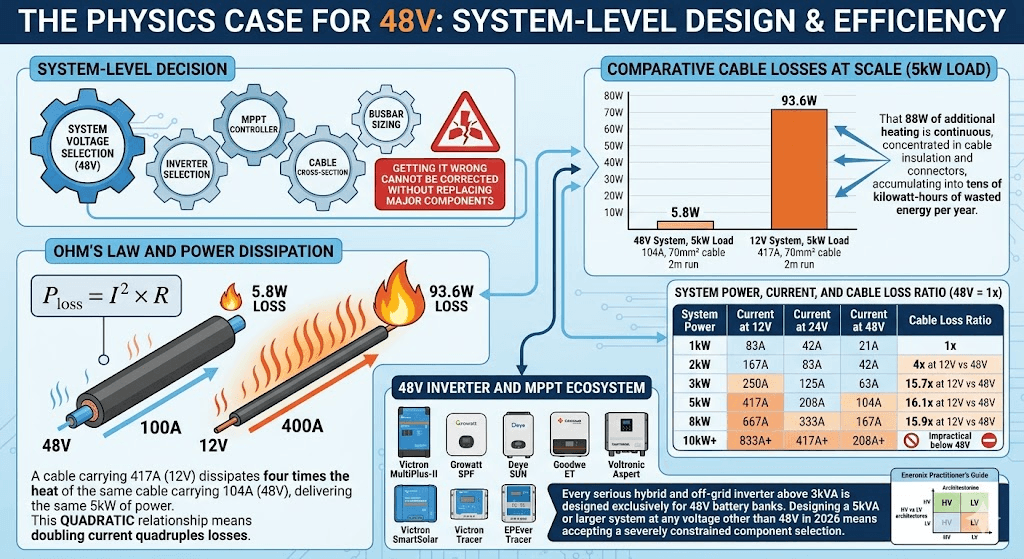
The 48V battery bank has become the de facto standard for any inverter system above 3kVA. The physics behind that choice are simple: power equals voltage multiplied by current (P = V x I). At a fixed power output, doubling the voltage halves the current. Halving the current cuts resistive cable losses by a factor of four, because those losses scale with the square of current (P_loss = I squared x R).At 48V, a 5kW load draws approximately 104A. At 12V, the same load draws 417A a figure that demands multiple parallel cable runs of 120mm squared cross-section and fusing arrangements that are both impractical and dangerous in a residential installation.
Choosing 48V is the easy part. Sizing the battery bank correctly is where most systems either succeed or fail. This guide covers every technical layer of the problem: cell-level specifications, usable capacity calculations, BMS dynamic limit management, series-parallel wiring constraints, charge parameter configuration, MPPT sizing, DC protection, and the thermal variables that make Nigerian installations behave differently from the datasheets written for temperate climates.
Every section goes deep. If you want a surface overview, this is not the right article. If you want to understand exactly what is happening inside your 48V system and why each design decision matters, read on.
Why Voltage Selection Is a System-Level Decision
System voltage selection is locked in at the design stage and affects every downstream component — inverter selection, MPPT controller ratings, cable cross-section, fuse ratings, and busbar sizing. Getting it wrong at the design stage cannot be corrected without replacing major components.
Current, Cable Losses, and the Inverse Square Relationship
Ohm’s Law and the power dissipation formula together explain why higher voltage is always preferred for high-power systems. For a conductor with resistance R carrying current I, power lost as heat is P_loss = I^2 x R. This quadratic relationship means that doubling the current quadruples the losses. A cable carrying 200A at 24V dissipates four times the heat of the same cable carrying 100A at 48V, even though both configurations deliver the same 2.4kW of power (ignoring efficiency).
In practical terms, a 70mm squared flexible copper cable rated for continuous DC service has an approximate resistance of 0.27 milliohms per metre. At 104A (48V system, 5kW load) over a 2-metre battery-to-inverter run, the resistive loss is 104 squared x 0.00027 x 2 = 5.8W. At 417A (12V system, same 5kW load, same cable), the loss is 417 squared x 0.00027 x 2 = 93.6W. That 88W of additional heating is continuous, concentrated in the cable insulation and connectors, and accumulates into tens of kilowatt-hours of wasted energy per year.
The choice between high-voltage and low-voltage inverter architectures has additional implications beyond cable losses. The Eneronix practitioner’s guide on high-voltage vs low-voltage inverters covers the complete decision framework — including how 48V low-voltage systems compare to 100V+ high-voltage battery strings used in larger commercial installations — with worked examples of where each architecture is most appropriate.
System Power
Current at 12V
Current at 24V
Current at 48V
Cable Loss Ratio (48V = 1x)
1kW
83A
42A
21A
1x
2kW
167A
83A
42A
4x at 12V vs 48V
3kW
250A
125A
63A
15.7x at 12V vs 48V
5kW
417A
208A
104A
16.1x at 12V vs 48V
8kW
667A
333A
167A
15.9x at 12V vs 48V
10kW+
833A+
417A+
208A+
Impractical below 48V
48V Inverter and MPPT Ecosystem
Every serious hybrid and off-grid inverter above 3 kVA — the Victron MultiPlus-II 48/5000, Growatt SPF 5000TL HVM-48V, Deye SUN-5K-SG04LP3, GoodWe ET 5K, and Voltronic Axpert MKS 5K — is designed exclusively for 48 V battery banks. The 48 V MPPT charge controller ecosystem (Victron SmartSolar, EPEver Tracer BN, Growatt SPF series built-in MPPT) similarly targets 48 V as the primary battery bus voltage above 3 kW of solar input. Designing a 5 kVA or larger system at any other voltage in 2026 means accepting a severely constrained component selection.
Understanding 48V LiFePO4 Cell Architecture and Specifications
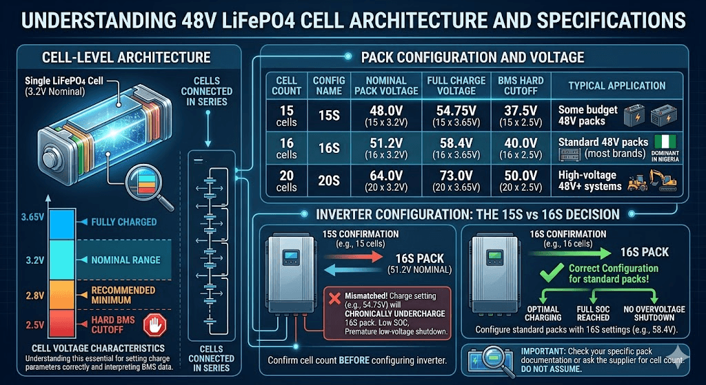
A 48V LiFePO4 battery is an assembly of individual LiFePO4 cells connected in series to reach the nominal 48V system voltage. Understanding the cell-level architecture is essential for setting charge parameters correctly and for interpreting BMS data during operation.
Cell Nominal Voltage and Pack Configuration
A single LiFePO4 cell has a nominal voltage of 3.2V, a fully charged voltage of 3.65V, and a fully discharged cutoff of approximately 2.5V (hard BMS cutoff) to 2.8V (recommended operational minimum). The number of cells in series determines the pack voltage.
Cell Count
Config Name
Nominal Pack Voltage
Full Charge Voltage
BMS Hard Cutoff
Typical Application
15 cells
15S
48.0V (15 x 3.2V)
54.75V (15 x 3.65V)
37.5V (15 x 2.5V)
Some budget 48V packs
16 cells
16S
51.2V (16 x 3.2V)
58.4V (16 x 3.65V)
40.0V (16 x 2.5V)
Standard 48V packs (most brands)
20 cells
20S
64.0V (20 x 3.2V)
73.0V (20 x 3.65V)
50.0V (20 x 2.5V)
High-voltage 48V+ systems
The overwhelming majority of 48V LiFePO4 rack batteries sold in Nigeria use the 16S configuration. This is important because it determines every charge voltage setting in your inverter. Setting a charge voltage calibrated for a 15S pack (54.75V) on a 16S pack results in chronic undercharging — the pack will never reach 100% SOC and will show premature low-voltage shutdowns as it slowly drifts toward a depleted baseline. Setting a 16S charge voltage (58.4V) on a 15S pack triggers repeated BMS overvoltage protection as individual cells are pushed above 3.65V during absorption.
Before configuring a single parameter on your inverter, confirm the cell count from the battery's technical datasheet not the product listing, the datasheet. The cell count is not always printed on the battery label and some resellers do not know it.
The Discharge Curve and Its Implications for SOC Estimation
LiFePO4 has an unusually flat discharge voltage curve compared to other lithium chemistries. Between approximately 20% and 90% state of charge, cell voltage varies by only about 0.1V per cell (from roughly 3.25V to 3.35V per cell in a 16S pack, that is 52V to 53.6V at pack level). This flatness is excellent for system stability — the inverter sees a stable DC bus voltage throughout most of the discharge but it makes open-circuit voltage (OCV) measurement almost useless for SOC estimation in real time.
A 16S pack at 60% SOC reads approximately 52.8V. The same pack at 40% SOC reads approximately 52.2V. The 0.6V difference is within the noise floor of most inverter voltage measurement circuits, especially under load. This is why SOC estimation in LiFePO4 systems must rely on coulomb counting (integrating current over time) rather than voltage measurement, and why a properly communicating BMS with accurate coulomb counting is not optional for reliable SOC display.
The steep voltage drop below 20% SOC (cells approach 2.8V rapidly) and above 95% SOC (cells spike toward 3.65V rapidly) are the only voltage-based SOC reference points that are reliable. A well-configured system uses these endpoints for periodic SOC calibration while relying on coulomb counting between them.
Capacity: Rated vs Usable vs Delivered
Three capacity figures matter for system design, and they are not the same number.
Rated capacity is the nameplate figure measured at 0.2C discharge rate (for a 100Ah battery, that is a 20A discharge) at 25 degrees Celsius to the hard cutoff voltage. This is the number printed on the label.
Usable capacity is rated capacity multiplied by the operating DoD. For daily cycling at 80% DoD, a 100Ah battery delivers 80Ah of usable capacity. For a more conservative 70% DoD (extending cycle life beyond the standard specification), it delivers 70Ah.
Delivered capacity is usable capacity adjusted for discharge rate and temperature. At higher discharge rates (above 0.5C), LiFePO4 capacity reduces slightly — a 100Ah battery discharged at 1C (100A) delivers approximately 95 to 98Ah rather than 100Ah. At temperatures above 40 degrees Celsius, delivered capacity is typically 2 to 5% below the 25-degree rating. Both derating factors compound: a battery in a hot Nigerian equipment room being discharged at high rate delivers less capacity than the nameplate suggests.
Capacity Type
Definition
Example (100Ah, 16S, LiFePO4)
Rated (nameplate)
0.2C discharge at 25C to BMS hard cutoff
100Ah = 5.12kWh
Usable at 80% DoD
Rated x 0.80
80Ah = 4.10kWh
Usable at 70% DoD
Rated x 0.70
70Ah = 3.58kWh
Delivered (35C, 0.5C rate)
Rated x 0.97 x 0.96 approx.
~93Ah = 4.76kWh
Delivered (42C, 1C rate)
Rated x 0.95 x 0.92 approx.
~87Ah = 4.45kWh
BMS Architecture: CVL, CCL, DCL, and Dynamic Limit Management
The Battery Management System is the intelligence layer of a LiFePO4 bank. Understanding how a quality BMS communicates dynamic limits to the inverter is what separates a properly functioning lithium system from one that ages at twice the expected rate.
The Three Dynamic Limits: CVL, CCL, and DCL
A communicating BMS continuously broadcasts three critical parameters to the inverter via CAN bus or RS485. These are the Charge Voltage Limit (CVL), the Charge Current Limit (CCL), and the Discharge Current Limit (DCL). Understanding what each parameter does and when it changes is fundamental to diagnosing charge behaviour problems. The Eneronix deep-dive on CVL, CCL, and DCL — understanding dynamic battery limits in real time explains each parameter in detail, including how a quality BMS uses them to protect cells from stress at the top and bottom of the SOC range.
CVL (Charge Voltage Limit) is the maximum voltage the inverter should apply to the battery at any point in the charge cycle. On a healthy 16S pack, CVL starts at the full absorption voltage (typically 58.4V) and is reduced by the BMS as individual cells approach their upper voltage limit. If the BMS detects one cell group approaching 3.65V while others are still at 3.55V (a sign of imbalance), it will reduce CVL to slow the charge rate, giving the balancer time to redistribute charge. A fixed charge voltage setting in the inverter cannot do this.
CCL (Charge Current Limit) is the maximum charge current the inverter should deliver at any point. CCL starts at the battery’s maximum rated charge rate (typically 0.5C for most 48V LiFePO4 modules) and is progressively reduced by the BMS as the pack approaches full charge and as temperature rises above the rated range. In Nigerian conditions where battery temperatures commonly reach 38 to 42 degrees Celsius in afternoon charging sessions, the BMS may reduce CCL to 50 to 70% of the rated maximum to protect the cells from heat stress during high-current charging.
DCL (Discharge Current Limit) is the maximum current the inverter can draw from the battery. DCL is normally set at the battery’s rated continuous discharge current and is reduced by the BMS when cell temperature is high, when SOC falls below approximately 15 to 20%, or when a cell group voltage begins to drop faster than expected (indicating a weakening cell). When the BMS reduces DCL, it is signalling to the inverter to reduce load. On a properly configured DVCC system, the inverter responds by shedding non-essential loads or reducing its own power output.
A system running without BMS communication has no CVL, CCL, or DCL. The inverter applies a fixed charge voltage and draws current without limit. This works for months or years until a cell goes out of balance, temperatures spike, or a cell group begins to fail. By then the damage is compounded by the absence of any protective signal from the bank.
Distributed Voltage and Current Control: DVCC
DVCC is the Victron firmware framework that enables the inverter, MPPT controller, and BMS to exchange CVL, CCL, and DCL values in real time and coordinate charge decisions across all charge sources simultaneously. When DVCC is active and a communicating BMS is connected, the inverter does not charge at a fixed voltage. It charges at whatever voltage the BMS is currently requesting, at whatever current the BMS permits, and adjusts dynamically as those limits change throughout the charge cycle.
Non-Victron inverters (Growatt, Deye, Goodwe) implement similar closed-loop BMS communication under different names, but the underlying mechanism is the same: the BMS broadcasts limits, the inverter obeys them. The critical configuration requirement is that the inverter’s battery type be set to the correct lithium communication mode and that the CAN bus or RS485 connection be wired with the correct pinout and set to the matching baud rate. A CAN bus wired with reversed CANH and CANL signals will produce no communication error message in most inverters — it will simply fail silently, leaving the system running on fixed settings.
Cell Balancing: Active vs Passive
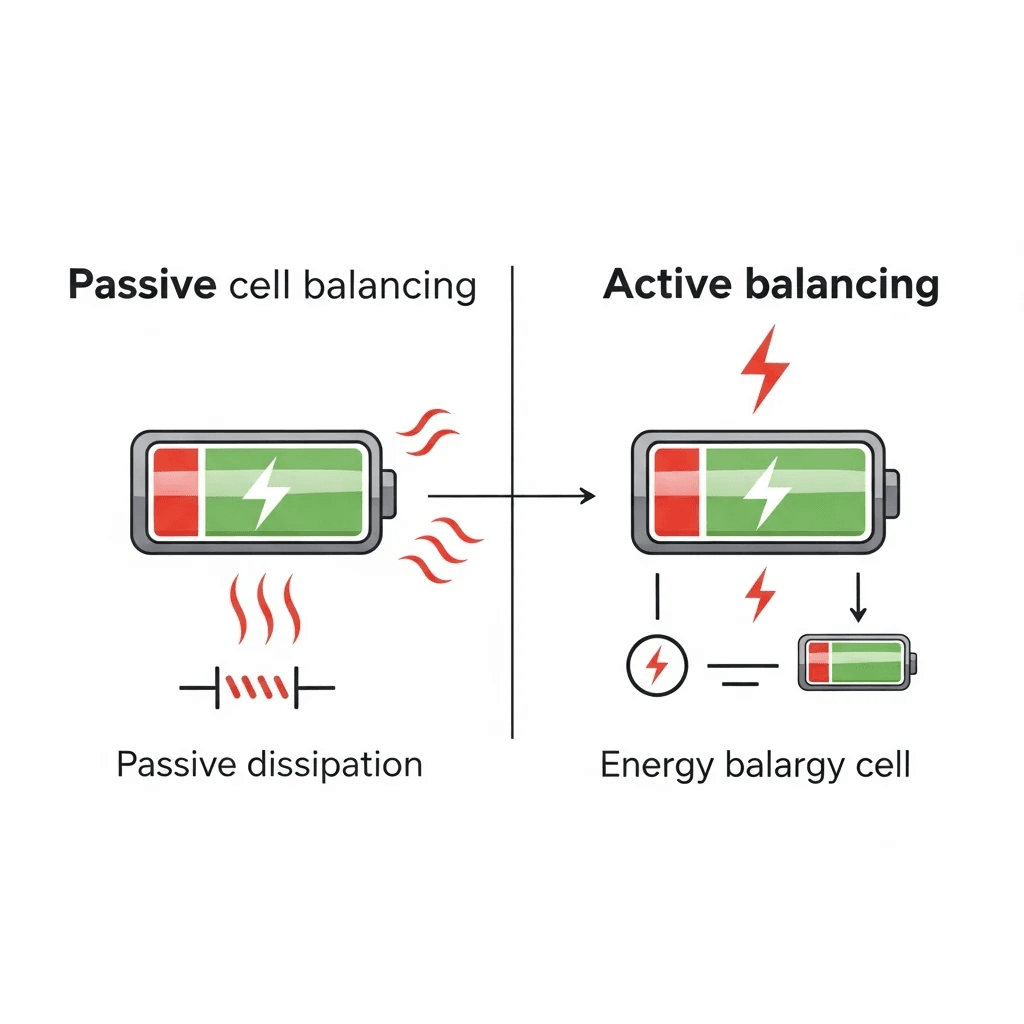
BMS balancing redistributes charge between cell groups to keep all cells at the same voltage. Passive balancing dissipates excess energy from higher-voltage cells as heat through bypass resistors. It is simple, cheap, and universal in consumer-grade BMS hardware. Its limitation is balancing current — most passive BMS units balance at 50 to 200mA, which is adequate for maintaining balance in a well-matched cell set but insufficient for correcting significant imbalance in a bank that has been cycling out of balance for months.
Active balancing transfers charge from higher-voltage cells to lower-voltage cells rather than dissipating it. Active balancing currents of 1 to 5A are achievable with modern balancer ICs, which means meaningful imbalance can be corrected within a single charge cycle rather than over dozens of cycles. Active balancing is standard in Pylontech and most Tier-1 rack batteries but absent from many budget modules and locally assembled packs.
In Nigerian conditions where cells experience higher thermal stress and more varied charge rates, active balancing is a meaningful quality differentiator. A pack where cells are running at different temperatures due to uneven airflow will naturally develop imbalance over time. Active balancing corrects this continuously; passive balancing can only slow its progression.
The Complete 48V Battery Bank Sizing Methodology
A correct sizing calculation requires five sequential steps. Each step’s output becomes an input to the next. Skipping or approximating any step propagates errors forward and typically results in either a bank that runs out of energy by 3am or one that is 40% larger than necessary.
Step 1: Detailed Load Audit
List every load the inverter system will power. For each load, record the nameplate wattage (or measured wattage if available — nameplate figures are often conservative), the operating mode (continuous vs cycling), and the number of hours per day it operates. Multiply watts by hours to get Wh/day for each appliance.
Appliance
Rated W
Power Factor / Notes
Actual W
Hours/Day
Wh/Day
1.5HP inverter AC (BLDC compressor)
1,119W
PF ~0.95, inrush 4.5x rated
1,063W avg
5h
5,315Wh
Inverter-type refrigerator
150W
Cycles ~50% duty
75W avg
24h
1,800Wh
LED lighting (10 x 9W)
90W
PF ~0.95
86W
6h
516Wh
DC ceiling fans x3 (40W each)
120W
Pure resistive
120W
12h
1,440Wh
55-inch LED TV + decoder
130W
Standby 8W excluded
130W
5h
650Wh
Laptop x2 (via AC adapter)
90W
PF ~0.98
88W
8h
704Wh
Router + fibre ONT
25W
Continuous
25W
24h
600Wh
Phone chargers x4 (phantom load)
10W
Estimated
10W
8h
80Wh
TOTAL
—
—
~1,597W avg running
—
11,105Wh/day
Two important distinctions in this audit: average running wattage versus peak wattage, and duty cycle. The AC above is rated at 1,119W but the average running power across a 5-hour operating window (including partial-load operation as the thermostat cycles) is approximately 1,063W. The refrigerator runs continuously but its compressor only operates at approximately 50% duty cycle, so its average contribution is 75W rather than 150W. Using nameplate ratings without these corrections produces a load figure 15 to 25% higher than the real daily energy demand, leading to systematic oversizing of the battery bank.
Step 2: Define System Autonomy
Autonomy is the duration in hours or days the battery must sustain the load without any charging input from solar panels or grid. In Nigeria, the practical autonomy target for most residential systems is one full overnight period — typically 8 to 14 hours from sunset to the point where solar production exceeds the morning load the following day.
For systems in areas with frequent multi-day cloud cover (common in the Niger Delta from June through September), a 1.5-day autonomy buffer is prudent. For commercial systems where outages have direct revenue impact, 2-day autonomy is standard. Every additional autonomy day multiplies required battery bank size proportionally.
For this worked example, we use a single overnight autonomy of 10 hours. Not all loads run all night — the AC operates for 5 of those hours, the TV for 0 hours overnight, laptops for 2 hours. The overnight load profile is therefore approximately 800W average rather than the daytime 1,597W.
Overnight energy required = 800W x 10h = 8,000Wh.
Step 3: Calculate Required Usable Energy, Corrected for Efficiency and Temperature
Required usable energy = Overnight demand / Inverter efficiency / Temperature derating factor
Using a high-quality inverter at 93% efficiency and a 5% temperature capacity derating for a non-air-conditioned battery room in Lagos:
8,000Wh / 0.93 / 0.95 = 9,054Wh of usable energy required from the battery bank.
The temperature derating is conservative but important. A battery rated for 100Ah at 25 degrees Celsius may deliver only 93 to 97Ah at 38 to 42 degrees Celsius (a realistic afternoon temperature in a poorly ventilated Nigerian equipment room). Applying a 5% derating builds this into the design without requiring precise temperature measurement.
Step 4: Calculate Required Installed Capacity
Divide required usable energy by operating DoD to find the total installed capacity needed.
At 80% DoD: 9,054Wh / 0.80 = 11,318Wh, rounded up to 11.5kWh of installed battery capacity.
Convert to amp-hours at the nominal system voltage. For a 16S LiFePO4 bank with 51.2V nominal:
11,500Wh / 51.2V = 225Ah of 48V bank capacity required.
Step 5: Check Both the Energy Constraint and the Current Constraint
The energy calculation gives you the minimum Ah required for runtime. The current constraint gives you the minimum number of modules required to safely supply the inverter’s peak load. Both constraints must be checked and the module count sized to satisfy whichever requires more units.
Energy constraint: 225Ah required. Using 100Ah modules: 225Ah / 100Ah = 2.25, round up to 3 modules (300Ah, 15.36kWh).
Current constraint: Maximum inverter draw at 5kVA is 5,000W / 48V = 104A. If each 100Ah module is rated for 50A continuous discharge, two modules in parallel deliver 100A — just under the inverter’s full-load draw. Three modules deliver 150A continuous, providing 46A of headroom and allowing for motor startup surges without triggering BMS over-current protection.
In this case, both constraints point to 3 modules as the minimum. The energy calculation requires 3 modules and the current calculation confirms 3 modules. If either constraint had required 4, the bank would be sized at 4.
Never take the smaller answer between the energy and current constraints. Size to whichever requires more modules. A bank that is correctly sized for energy but undersized for current will trip BMS over-current protection at exactly the moment your load is highest.
Series-Parallel Wiring: Electrical Constraints and Practical Rules
The wiring configuration of a 48V battery bank is not just an electrical diagram exercise. It is a current distribution problem. Incorrect wiring causes systematic current imbalance between modules, which causes one module to age faster than its neighbours, which eventually causes the whole bank to perform below its rated specification.
48V Module Banks: Parallel Wiring Only
When using 48V modules (the standard for all major LiFePO4 rack batteries in Nigeria), the only wiring operation needed is parallel connection of multiple modules to increase amp-hour capacity. Series connection is not applicable — you already have the correct voltage. Connect all module positive terminals to a common positive busbar and all module negative terminals to a common negative busbar. The inverter connects across the busbars, not directly to any individual module.
12V Cell Banks: Series-Parallel Wiring
When using 12V LiFePO4 batteries (less common but present in some Nigerian installations), series strings of 4 batteries are required to reach 48V. To increase capacity beyond a single 4-battery string, complete series strings are connected in parallel. Never mix cells within a series string and paralleled cells between strings — the correct configuration is complete strings in parallel, not individual cells.
Config
Series x Parallel
Voltage
Total Capacity
Usable (80% DoD)
Min. Modules (50A/module limit)
4x 12V 100Ah
4S x 1P
48V
4.8kWh
3.84kWh
1 string
8x 12V 100Ah
4S x 2P
48V
9.6kWh
7.68kWh
2 strings
12x 12V 200Ah
4S x 3P
48V
28.8kWh
23.04kWh
3 strings
3x 48V 100Ah
1S x 3P
48V
14.4kWh
11.52kWh
3 modules
4x 48V 200Ah
1S x 4P
48V
38.4kWh
30.72kWh
4 modules
The Balanced Busbar Wiring Method
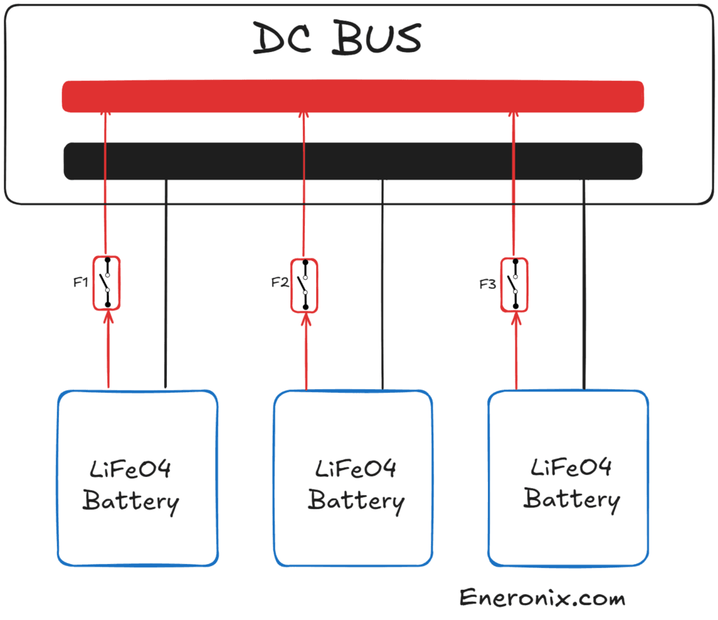
For parallel banks of three or more modules, the balanced busbar method is mandatory. Do not connect the inverter positive to one end of a row of batteries and the inverter negative to the other end. This creates a current path where the first battery in the row sees significantly more current than the last battery, because current takes the path of least resistance and the first battery is electrically closest to both the inverter positive and negative terminals.
The correct method: connect all battery positives to a copper busbar using equal-length cables of equal cross-section. Connect all battery negatives to a second copper busbar using equal-length cables of equal cross-section. Connect the inverter positive to the centre of the positive busbar and the inverter negative to the centre of the negative busbar. This configuration distributes current equally across all modules because every module sees the same total cable resistance to the inverter connection point.
Cable length discipline is not optional. A cable 10cm longer than its neighbour has a measurably higher resistance. At 100A total current, a 5% resistance difference between two parallel 50A-rated modules causes one module to supply 52.5A and the other to supply 47.5A. Over thousands of cycles, the module carrying the higher current develops faster capacity fade and higher internal resistance, further compounding the imbalance.
All cables from modules to busbars must be the same length, same cross-section (minimum 50mm squared for banks above 150A continuous), and same terminal type.
Busbars must be rated for the full bank current plus 25% safety margin. For a 3-module bank at 50A per module, the busbar carries 150A — use a busbar rated for at least 190A.
All module terminals and busbar connections must be torqued to the manufacturer’s specified value. Use a calibrated torque wrench, not estimated hand tightening.
Apply anti-oxidant compound (such as Noalox or equivalent) to all copper-to-copper and copper-to-terminal interfaces before final assembly to prevent oxidation-induced resistance increase over time.
Charge Parameter Configuration: Technical Reference for 16S LiFePO4
Incorrect charge parameters are the single most common cause of premature LiFePO4 degradation in Nigerian installations. Overcharge damages cells through lithium plating. Undercharge leaves cells in a chronic partial state that enables passive sulfation of BMS components and limits delivered capacity. Both failure modes are silent — the system appears to work normally until capacity fade becomes noticeable.
Absorption (Bulk) Voltage
For a 16S LiFePO4 pack, the correct absorption voltage is the voltage at which individual cells reach 3.65V under charge current. Under load, this is typically 57.6V to 58.4V at the pack terminals, depending on the internal resistance of the BMS and cell connections. Most Tier-1 manufacturers (Pylontech, Blue Carbon) specify 58.4V as the maximum charge voltage. Some specify 57.6V as a conservative daily maximum with 58.4V reserved for the balancing charge.
Do not set the charge voltage above the manufacturer’s specified maximum. The 3.65V per cell upper limit is not a guideline — it is the threshold above which lithium deposition begins on the graphite anode, which is irreversible and reduces cycle life with every occurrence.
Float Voltage: Why LiFePO4 Does Not Need It
Lead-acid batteries require a float charge to maintain full charge while connected to the inverter, because they self-discharge at 1 to 5% per week. LiFePO4 self-discharges at approximately 1 to 3% per month — 10 to 20 times slower. The Eneronix article on why lithium batteries do not need float charging explains the electrochemical reason for this: LiFePO4 cells held at float voltage undergo continuous low-level lithium intercalation at the anode surface, which adds cumulative stress with no benefit for a chemistry that barely self-discharges.
The recommended configuration for most LiFePO4 systems is to set float voltage equal to the absorption voltage, which causes most inverters to terminate the charge cycle and allow the battery to drift down naturally until the next charge event. Alternatively, set float to a value below the battery’s resting voltage (approximately 53.6V for a 16S pack) which prevents the inverter from actively maintaining a float charge.
Low Voltage Cutoff: Inverter vs BMS
Two low-voltage cutoffs exist in a LiFePO4 system and they must be configured in the correct relationship to each other. The inverter’s low-voltage cutoff (set by the user in the inverter menu) should trigger at approximately 46V to 48V for a 16S pack, corresponding to approximately 20 to 25% SOC on the discharge curve. The BMS hard cutoff, the voltage at which the BMS physically disconnects the load should be set at approximately 40V to 42V for a 16S pack (2.5V to 2.625V per cell).
The inverter cutoff must always be set above (higher voltage than) the BMS cutoff by at least 2V. If they are set at the same voltage, the inverter’s load causes voltage sag that triggers the BMS cutoff before the inverter detects the low voltage, causing an abrupt disconnect rather than a controlled shutdown. If the inverter cutoff is set below the BMS cutoff, the BMS will trip first every time, causing repeated hard shutdowns that stress both the BMS relay and the cells.
Parameter
15S Pack Value
16S Pack Value
Notes
Absorption voltage
54.0V to 54.75V
57.6V to 58.4V
Use manufacturer datasheet value
Float voltage (if used)
52.5V to 53.25V
56.0V to 56.8V
Or disable float entirely
Inverter low-voltage cutoff
42.0V to 43.5V
45.0V to 47.0V
Must be above BMS hard cutoff
BMS hard cutoff (low)
37.5V to 39.0V
40.0V to 42.0V
Hardware protection — rarely triggers
BMS hard cutoff (high)
54.75V to 55.5V
58.4V to 59.2V
Overvoltage protection
Charge current limit (CCL)
0.2C to 0.5C rated
0.2C to 0.5C rated
Verify in battery datasheet
Recommended daily max SOC
90%
90%
Reduces cell stress, extends life
Recommended daily min SOC
20%
20%
Preserves cycle life at low end
Matching Solar Input to the Battery Bank: Array Sizing and MPPT Configuration
Peak Sun Hours and Daily Energy Production
Nigeria’s solar resource varies significantly by region and season. The figures below are long-term averages from NASA POWER atmospheric data and represent daily peak sun hours (PSH) — the equivalent number of hours at 1,000W/m squared irradiance that produce the same energy as the actual variable irradiation profile.
Region
Annual Average PSH
Dry Season PSH (Nov-Feb)
Wet Season PSH (Jun-Sep)
Key Cities
North (Sahelian)
6.0 to 6.5h
6.5 to 7.0h
5.0 to 5.5h
Kano, Maiduguri, Sokoto
North-Central
5.5 to 6.0h
6.0 to 6.5h
4.5 to 5.0h
Abuja, Jos, Kaduna
South-West
4.5 to 5.0h
5.0 to 5.5h
3.5 to 4.5h
Lagos, Ibadan, Abeokuta
South-East
4.0 to 4.5h
4.5 to 5.0h
3.0 to 4.0h
Enugu, Owerri, Umuahia
South-South
3.8 to 4.5h
4.5 to 5.0h
2.8 to 3.8h
Port Harcourt, Warri, Benin
Use the wet season PSH value for system sizing in climate-sensitive applications. Sizing to annual average PSH will leave the system undersupplied for 4 to 5 months of the year during the rainy season, which is typically when grid power is also most unreliable.
Required Solar Array Size
Required panel capacity = Daily energy demand / PSH / System efficiency
System efficiency accounts for panel degradation from dust and heat (approximately 10 to 15% in Nigerian conditions), MPPT controller efficiency (typically 97 to 98%), cable losses, and battery charge efficiency (typically 97% for LiFePO4).
Using the worked example (11,105Wh/day), Lagos wet season PSH (4.0h), and overall system efficiency of 80%:
11,105Wh / 4.0h / 0.80 = 3,470Wp — round up to 3,500Wp (for example, 8 x 450W panels or 10 x 370W panels).
The Eneronix guide to solar array sizing for off-grid systems covers this calculation in detail, including how to account for shading losses, panel temperature derating (a significant factor in Nigerian heat where panel temperatures regularly reach 55 to 70 degrees Celsius), and how to adjust the array size when seasonal PSH varies significantly between dry and wet seasons.
Panel Wiring: Series, Parallel, and the MPPT Input Constraints
Solar panels must be wired to produce a DC voltage and current within the MPPT controller’s rated input range. For a 48V battery bank, the MPPT controller must accept array voltages significantly above 58.4V (the battery’s full charge voltage) to allow current to flow into the battery. Most quality MPPT controllers for 48V systems accept array Voc up to 100V to 150V depending on model. The Eneronix guide on series vs parallel solar panel wiring explains how connecting panels in series increases array voltage while keeping current constant, and how connecting in parallel increases current while keeping voltage constant — and which configuration is more efficient for a given MPPT controller input specification.
Critical constraint for Nigerian installations: MPPT controllers are rated with a maximum input voltage (Voc max) that must not be exceeded even under cold-morning open-circuit conditions. Although Nigeria rarely experiences genuinely cold mornings, harmattan season in the north and early-morning temperatures in highland areas (Jos Plateau) can produce panel temperatures of 15 to 18 degrees Celsius. At lower temperatures, panel Voc increases by approximately 0.4% per degree Celsius below the Standard Test Condition temperature of 25 degrees Celsius. A 450W panel with a 37.6V Voc at STC reaches approximately 39.4V Voc at 15 degrees Celsius. Three such panels in series produce 118.2V — which must stay within the MPPT controller’s maximum input voltage rating.
MPPT Controller Sizing for a 48V Bank
The MPPT controller must be rated for the full short-circuit current (Isc) of the array plus a 25% safety margin. For an array of 8 x 450W panels wired as 2 strings of 4 panels in series (each string producing approximately 10A Isc), the total array Isc is approximately 20A. The MPPT controller must be rated for at least 25A input current and must have a maximum input voltage rating above the calculated cold-morning Voc of the series string.
The Eneronix worked example on MPPT controller sizing for a 48V lithium system walks through this calculation step by step for a real Nigerian system, including the Voc temperature correction, MPPT derating for array mismatch, and how to select the correct controller model from available options in the Nigerian market.
DC Protection: Fusing, Disconnects, and Cable Sizing
DC protection in a 48V battery system operates under different physical principles than AC protection. DC arcs do not self-extinguish at the voltage zero crossing the way AC arcs do, because DC has no zero crossing. A DC arc at 48V can sustain itself indefinitely once established, generating intense heat at the fault point. This is why DC fuses and switches must be specifically rated for DC service at the system voltage and current.
Main Battery Fuse Sizing
The main fuse between the battery positive busbar and the inverter protects the interconnecting cable from overcurrent in the event of an inverter fault. It is not sized to protect the inverter, the inverter has its own internal protection. It is sized to protect the cable.
Fuse rating = Cable continuous current rating x 1.0 (fuse at 100% of cable rating for DC systems, where derating is more conservative than AC).
For a 5kVA inverter drawing up to 104A continuous from a 48V bank, the minimum cable is 50mm squared flexible (rated for approximately 120A continuous in free air at 40 degrees Celsius). The fuse is rated at 125A, the nearest standard Class T or ANL fuse size above the cable rating. Do not use automotive blade fuses or AC MCBs in a 48V battery DC circuit. They are not rated for DC arc interruption at 48V and will fail to clear a fault safely.
For a complete cable sizing reference covering cross-section selection, voltage drop calculation, and derating factors for Nigerian ambient temperatures, the Eneronix guide on DC cable sizing for off-grid solar systems provides tables for all common cable sizes and system currents, along with the full voltage drop formula applied to worked examples.
Individual Module Fusing in Parallel Banks
Each module in a parallel bank must have its own inline fuse between the module positive terminal and the positive busbar. Without individual module fusing, a short circuit in one module’s BMS or connection creates a fault current path through the other modules rather than through a protective device. The other modules supply fault current limited only by their BMS and internal resistance, which may not be sufficient to prevent damage before the main fuse clears.
Individual module fuse rating = Module maximum continuous discharge current x 1.25. For a 100Ah module rated at 100A continuous discharge, the per-module fuse is rated at 125A.
DC Isolator Switch
A DC isolator switch allows the battery bank to be disconnected from the inverter safely for maintenance, commissioning, or emergency shutdown. The switch must be rated for DC service at a minimum of 1.25x the system voltage (60V DC minimum for a 48V bank) and 1.25x the maximum continuous current (130A minimum for a 104A draw).
Do not use an AC circuit breaker or AC isolator switch in a DC battery circuit. AC switches use a design that relies on the AC voltage zero crossing to extinguish the arc when opening under load. A 48V DC arc will sustain itself through an AC switch, welding the contacts and creating a fire risk.
Thermal Management for Nigerian Conditions
LiFePO4 cells have an optimal operating and storage temperature range of 20 to 35 degrees Celsius. Above 35 degrees Celsius, the Arrhenius equation predicts accelerating solid electrolyte interphase (SEI) growth on the anode surface — a form of irreversible capacity loss that compounds with each cycle. The SEI growth rate approximately doubles for every 10 degree Celsius increase in temperature above the optimal range.
Expected Capacity Loss at Nigerian Operating Temperatures
Battery Room Temperature
Annual Capacity Loss (Estimated)
Remaining Capacity at Year 5
Remaining Capacity at Year 10
25C (climate-controlled)
~1.5% per year
~92.5%
~85%
35C (well ventilated)
~2.5% per year
~87.5%
~75%
40C (poor ventilation)
~5.0% per year
~75.0%
~50%
45C (sealed room, afternoon peak)
~8.0% per year
~60.0%
~20% (early replacement)
The 45-degree scenario is not hypothetical. A sealed equipment room in Lagos with a corrugated iron roof and no ventilation reaches 50 degrees Celsius or above on still afternoons from March through October. Batteries installed in such a room will require replacement in 4 to 6 years regardless of how well they were sized and configured.
Practical Thermal Management for Nigerian Installations
Orient battery racks with at least 50mm clearance on all sides for convective airflow. Do not stack batteries flat against a wall with no air gap.
Install a minimum 150mm diameter axial fan to force airflow across the battery faces if the room temperature exceeds 35 degrees Celsius for more than 4 hours per day. A 20W fan running 12 hours per day consumes 87.6kWh per year — trivial relative to the battery bank value it protects.
Use a min-max thermometer in the battery room and log the peak temperature for the first three months of operation. If the recorded peak exceeds 40 degrees Celsius, add ventilation before the next hot season rather than after the first BMS thermal fault.
If the battery room shares a wall with a west-facing exterior, add mineral wool or foam insulation to that wall. West-facing walls in Lagos receive direct afternoon sun from 1pm to 6pm for most of the year and transfer significant heat into the room.
Size the battery bank with a thermal buffer: add one additional module beyond the energy and current-constrained minimum if the installation environment cannot be maintained below 38 degrees Celsius. This buffer absorbs the reduced delivered capacity from thermal derating without compromising backup duration.
Commissioning Checklist for a 48V LiFePO4 Bank
Commissioning errors are responsible for a disproportionate share of early battery failures in Nigerian solar installations. A 30-minute commissioning check at installation prevents the most common configuration problems from compounding silently over months of operation.
Verify cell count from the datasheet before configuring any inverter parameters. Confirm 15S or 16S and set all voltage parameters accordingly.
Charge each module individually to 100% SOC before connecting modules in parallel. Confirm all modules are within 0.5V of each other at the pack level before making parallel connections.
Wire all modules to the busbar using equal-length, equal-cross-section cables. Torque all terminal bolts to the manufacturer’s specified value using a calibrated torque wrench.
Install individual module fuses and the main battery fuse before energising the system.
Connect the BMS communication cable (CAN bus or RS485) between the battery bank and the inverter. Verify the cable pinout against both the battery and inverter documentation — do not assume industry-standard pinout.
Power on the inverter and navigate to the battery status display. Confirm that the inverter is displaying battery SOC, cell voltage, and temperature data from the BMS. If these fields show 0, dashes, or static values, the BMS communication link has not been established.
Verify the charge voltage applied by the inverter matches the battery datasheet specification. Observe the inverter’s charge voltage display during an active charge cycle — it should match or be within 0.2V of the CVL being broadcast by the BMS.
Run the system through a partial discharge to 50% SOC and then back to 100% SOC while monitoring cell voltage balance in the BMS display. All cell groups should stay within 50mV of each other throughout the cycle. Cell voltage spread above 100mV at any point indicates imbalance that must be investigated before the system is left unattended.
Record the initial commissioned SOC, cell voltages, temperature, and installation date in a commissioning log. This record is the baseline for any future warranty claim and for detecting capacity fade in annual checks.
Register the battery warranty with the manufacturer or authorised distributor within 30 days of commissioning. Photograph the battery serial number labels and store the images off-site.
Annual Performance Verification and Capacity Testing
LiFePO4 capacity fade is gradual and often unnoticed until backup runtime drops below the design requirement. An annual capacity test catches early degradation while there is still time to plan a replacement rather than be forced into an emergency purchase.
The Capacity Test Procedure
The test requires a known, stable load and accurate energy measurement. Charge the bank to 100% SOC using the inverter’s charge cycle. Disconnect solar input. Apply a constant known load (for example, a resistive load bank or a stable combination of appliances with measured wattage) and allow the bank to discharge to the inverter’s low-voltage cutoff. Record the kWh delivered by the inverter’s energy meter or a dedicated battery monitor. Compare to the theoretical usable capacity (installed kWh x DoD).
A healthy bank in year one should deliver 95 to 100% of its theoretical usable capacity. A bank delivering less than 80% of theoretical capacity has experienced significant degradation and should be evaluated for replacement within the next 12 to 18 months. A bank delivering less than 70% has reached functional end of life for its designed application.
Cell Voltage Imbalance as an Early Warning Indicator
Before capacity loss becomes visible in backup duration, cell voltage imbalance is typically the first sign that a cell group is beginning to fail. During a charge cycle, a weakening cell group reaches its upper voltage limit (3.65V) before the other groups — causing the BMS to reduce CVL and terminate the charge early to protect that cell, while the other groups are still at 3.55V. During discharge, the same weak cell group hits its lower voltage limit early, causing the BMS to raise the DCL or trigger an early shutdown.
Monitor cell voltage spread monthly via the BMS display. A spread below 50mV between the highest and lowest cell group voltages at any point in the cycle is normal. A persistent spread above 100mV indicates a weakening cell group. A spread above 200mV means the BMS balancer cannot keep up with the imbalance and proactive module replacement should be planned.
Frequently Asked Questions
Q: What is the difference between a 15S and 16S LiFePO4 battery and how do I tell which one I have?
A 15S pack contains 15 LiFePO4 cells in series, giving a nominal voltage of 48.0V and a full charge voltage of 54.75V. A 16S pack contains 16 cells in series, giving a nominal voltage of 51.2V and a full charge voltage of 58.4V. The vast majority of 48V LiFePO4 rack batteries sold in Nigeria use 16S. To confirm, check the technical datasheet for the battery model, look for either the cell count directly or the maximum charge voltage, which will tell you the configuration.
If the datasheet states a maximum charge voltage of 58.4V, it is 16S. If it states 54.75V, it is 15S. If you cannot access the datasheet, use a multimeter to measure the fully charged pack voltage, a reading of 57.5V to 58.5V indicates 16S, and 54.0V to 55.0V indicates 15S.
Q: Can I charge a 48V LiFePO4 bank with a generator through my inverter?
Yes, provided your inverter has an AC input (charger) function, which virtually all hybrid and off-grid inverters above 3kVA do. The generator connects to the inverter’s AC input, the inverter’s internal charger converts the AC to DC at the correct charge voltage and current for the battery bank. The charge parameters (voltage, current limit) configured in the inverter apply regardless of whether the charging source is solar via the MPPT, grid, or generator.
Generator charging should use the same charge voltage and current settings as solar charging. The only additional consideration is generator sizing — a 5kVA inverter charging a depleted 15kWh bank at 0.5C (approximately 75A at 48V, or 3.6kW of charge power) requires a generator rated for the sum of the charge power plus any AC loads simultaneously supplied by the inverter.
Q: Why does my 48V battery bank voltage drop sharply as soon as I apply a load, even when the SOC shows 80%?
This is voltage sag caused by the internal resistance of the battery bank. Every battery has an internal resistance (measured in milliohms per cell) that produces a voltage drop proportional to the discharge current when load is applied. A 3-module bank of 100Ah cells with approximately 1.5 milliohm total internal resistance will sag by 1.5 milliohm x 100A = 0.15V under 100A load — which at the 48V scale is small. However, if the internal resistance is higher due to poor connections, aged cells, or cold temperatures, the sag is more pronounced.
If voltage sag is causing the inverter to cut off loads at apparent 80% SOC, first check all busbar and terminal connections for resistance with a milliohm meter. Then check the cable cross-section between the battery and inverter for undersizing. Finally, if both check out, the battery bank may have higher internal resistance than expected due to early cell aging.
Q: How do I know if my BMS is communicating correctly with my inverter?
The inverter’s battery status screen should display at minimum: state of charge as a percentage, battery voltage, and charge or discharge current. On inverters with full BMS integration (Victron with DVCC active, Growatt with BMS communication enabled, Deye with CAN bus connected), it should also display battery temperature and may display individual cell group voltages. If the SOC display shows a static value that does not change during charge or discharge, or shows 100% or 0% permanently, the communication link is broken and the inverter is running on voltage-based estimation rather than BMS data.
The most common causes are incorrect CAN bus pinout, mismatched baud rate settings, wrong protocol selection in the inverter menu, or a damaged communication cable. The Eneronix BMS troubleshooting guide covers the diagnostic procedure for each of these failure modes in sequence.
Q: What is the correct fuse size for a 3-module 48V 100Ah LiFePO4 bank connected to a 5kVA inverter?
Two fuse ratings are required. The per-module fuse protects each module’s connection to the busbar. For a 100Ah module with 100A continuous discharge rating, the per-module fuse is rated at 125A (100A x 1.25). Use a Class T or ANL fuse in a properly rated DC fuse holder. The main fuse between the busbar and the inverter protects the main interconnecting cable. For 50mm squared cable rated at 120A continuous, the main fuse is 125A to 150A.
Use the nearest standard DC-rated fuse size above the cable rating. All fuses must be DC-rated at a minimum of 80VDC (providing headroom above the 58.4V fully charged pack voltage plus arc voltage). Do not use AC-rated circuit breakers or fuses in any 48V DC circuit.
Q: My inverter shows the battery at 100% but it only runs my loads for 4 hours instead of the expected 8 hours. What is wrong?
This symptom has three common causes. First, the battery bank may have lost capacity due to thermal degradation, chronic overcharge, or cell imbalance — run a timed capacity test as described in the annual maintenance section to measure actual delivered kWh. Second, the inverter may be reporting SOC incorrectly because BMS communication is absent or misconfigured — the inverter is estimating SOC from open-circuit voltage rather than coulomb counting, and the flat LiFePO4 discharge curve makes this very inaccurate.
Third, the actual load may be higher than the designed load — measure the actual running wattage of the system under typical conditions with a clamp meter and compare to the original load audit assumptions. AC inverter compressors, aging refrigerators, and UPS units that have been added since the original system design are common causes of higher-than-expected loads.
Q: Can I expand a 3-module 48V bank to 5 modules 2 years after installation?
Technically yes, practically risky. Adding 2 new modules to a 2-year-old 3-module bank creates a parallel bank where the new modules have lower internal resistance and higher capacity than the aged modules. Under discharge, the lower-resistance new modules supply proportionally more current than the older modules, which means they cycle more deeply and age faster than they should — partially negating the capacity expansion benefit.
Before expanding, run a capacity test on the existing modules to quantify how much capacity they have lost. If the existing modules retain more than 85% of their original capacity, expansion is relatively safe. If they have lost more than 15%, the most cost-effective path is full bank replacement with a correctly sized new bank of identical modules rather than expansion.
Q: What is the minimum and maximum state of charge I should operate my LiFePO4 bank at for maximum longevity?
For maximum cycle life, operate the bank between 20% and 90% SOC in daily use. Avoid charging to 100% every day unless you need the full capacity for that specific night. Charging to 90% and discharging to 20% represents approximately 70% utilisation of the nameplate capacity, but at this operating window a quality LiFePO4 bank rated for 3,500 cycles at 80% DoD typically achieves 5,000 to 6,000 cycles — a 40 to 70% extension.
Reserve the 100% charge for occasions when you anticipate unusually high overnight demand or before an extended period of reduced solar production. The BMS on most quality rack batteries allows you to set a maximum daily charge level in the inverter or BMS configuration to enforce this without manual intervention.
Conclusion
A 48V LiFePO4 battery bank is not a product. It is a system — cells, BMS, wiring, charge parameters, thermal environment, and inverter configuration all interact continuously. Getting the energy sizing right but the charge parameters wrong produces a bank that degrades in 3 years instead of 10. Getting the charge parameters right but the wiring wrong produces a bank where one module fails while the others are still healthy. Getting everything right but ignoring the thermal environment produces a bank that meets spec in the harmattan and fails in August.
The calculations in this guide are the foundation. The wiring discipline, charge parameter precision, BMS communication verification, and thermal management are what actually determine whether your 48V system performs to its potential over a decade of daily cycling in Nigerian conditions.
Every step in the commissioning checklist exists because there is a specific failure mode it prevents. None of them are optional.
Size from actual load audit data, not inverter nameplate. Apply DoD, inverter efficiency, and temperature derating to every capacity calculation.
Check both the energy constraint and the current constraint. Size to whichever requires more modules.
Confirm 15S or 16S cell configuration from the datasheet before setting a single charge parameter.
Set float voltage below resting pack voltage or disable float entirely. LiFePO4 does not need and is harmed by continuous float charging.
Wire parallel banks to a shared busbar with equal-length, equal-cross-section cables. Current balance is a cable geometry problem, not just a BMS problem.
Verify BMS communication is active and the inverter is displaying live SOC, voltage, and temperature data before considering the installation commissioned.
Run an annual capacity test. Detect cell imbalance before it becomes capacity loss. Detect capacity loss before it becomes a midnight outage.
I am Engr. Ubokobong Ekpenyong, a solar specialist and lithium battery systems engineer with over five years of hands-on experience designing, assembling, and commissioning off-grid solar and energy storage systems. My work focuses on lithium battery pack architecture, BMS configuration, and system reliability in off-grid and high-demand environments.
Contains information related to marketing campaigns of the user. These are shared with Google AdWords / Google Ads when the Google Ads and Google Analytics accounts are linked together.
90 days
__utma
ID used to identify users and sessions
2 years after last activity
__utmt
Used to monitor number of Google Analytics server requests
10 minutes
__utmb
Used to distinguish new sessions and visits. This cookie is set when the GA.js javascript library is loaded and there is no existing __utmb cookie. The cookie is updated every time data is sent to the Google Analytics server.
30 minutes after last activity
__utmc
Used only with old Urchin versions of Google Analytics and not with GA.js. Was used to distinguish between new sessions and visits at the end of a session.
End of session (browser)
__utmz
Contains information about the traffic source or campaign that directed user to the website. The cookie is set when the GA.js javascript is loaded and updated when data is sent to the Google Anaytics server
6 months after last activity
__utmv
Contains custom information set by the web developer via the _setCustomVar method in Google Analytics. This cookie is updated every time new data is sent to the Google Analytics server.
2 years after last activity
__utmx
Used to determine whether a user is included in an A / B or Multivariate test.
18 months
_ga
ID used to identify users
2 years
_gali
Used by Google Analytics to determine which links on a page are being clicked
30 seconds
_ga_
ID used to identify users
2 years
_gid
ID used to identify users for 24 hours after last activity
24 hours
_gat
Used to monitor number of Google Analytics server requests when using Google Tag Manager
1 minute
You can find more information in our Cookie Policy and .


")


