Introduction
Every post in this cluster has been building toward a complete, verified system specification. Post #8 established the theory behind inverter selection: the three-number problem of continuous rating, surge rating, and standby power, and the additional checks covering waveform quality, transfer speed, voltage window, and BMS communication. This post applies that framework to a single complete worked example using the same system parameters that have run through every calculation in this cluster since Post #1.
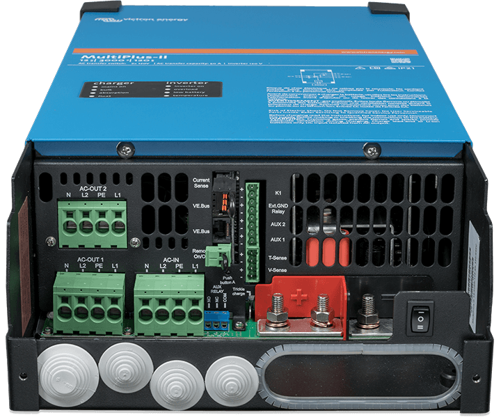
The candidate inverter-charger is the Victron Multiplus-II 48/3000/35-32. Every check in the selection framework will be performed against its published datasheet values. Where it passes, the margin will be documented. Where it fails, the failure will be stated clearly and two resolution paths will be evaluated.
I want to establish one expectation upfront: this worked example does not produce a clean pass on every check. The surge rating verification uncovers a genuine incompatibility between the base 3kVA model and the air conditioner compressor’s inrush demand. That finding is not a problem with the selection process. It is the selection process working correctly, identifying an incompatibility at the design stage rather than at the moment the client turns on the air conditioner for the first time. How that incompatibility is resolved is one of the most practically useful decisions this post covers.
The Off-Grid Inverter Sizing Framework and System Parameters
The inverter selection framework established in Post #8 has seven verification steps that must be satisfied in sequence before a candidate inverter-charger is accepted. The steps are continuous rating, surge rating, standby power, waveform and transfer speed, voltage window configuration, AC charging and generator integration, and BMS communication architecture. A candidate that satisfies six and fails one is not a marginally acceptable selection. It is a wrong selection, and the step it fails on determines exactly what goes wrong in the field.
The system parameters for this worked example are the same inputs that have run through every calculation in this cluster since Post #1:
| System Parameter | Value |
| Daily energy demand | 4,916Wh |
| Array STC rating | 2,400W (6 x 400W panels, 3S2P) |
| Battery system voltage | 48V LiFePO4 |
| MPPT controller | Victron SmartSolar MPPT 150/60 |
| Simultaneous continuous load | 1,950W (full occupancy with air conditioner) |
| Largest motor load | 1.5kW air conditioner compressor |
| Installation location | Coastal West Africa (~6°N latitude) |
The candidate inverter-charger and its published specifications are:
| Victron Multiplus-II 48/3000/35-32 | Published Specification |
| Continuous output | 3,000VA at 48V DC |
| Surge rating | 5,500VA for up to 3 milliseconds |
| AC charging current | 35A maximum |
| AC output current | 32A |
| Maximum charge power | 2,500W |
| Low voltage cutoff | Adjustable 38 to 48V |
| High voltage cutoff | Adjustable to 64V |
| Standby power | Approximately 15W |
| Output waveform | Pure sine wave |
| Transfer switch time | Less than 20 milliseconds |
Every check that follows uses these two tables as its input. Where the candidate passes, the margin is documented. Where it fails, the failure is stated and the resolution paths are evaluated before the next check proceeds.
For the derivation of the simultaneous continuous load figure and the load audit methodology that produced it, refer to our engineering guides on how to do a proper load audit before sizing an off-grid system, how to account for phantom loads and standby power in off-grid energy budgets, and how to select and size an off-grid inverter.
Step 1: Continuous Rating Verification
The continuous rating check establishes whether the candidate inverter can sustain the system’s maximum simultaneous load indefinitely without thermal protection activating. The governing equation and the design utilization target are carried forward from Post #8:
Minimum Continuous Rating = Simultaneous Continuous Load / Design Utilization Factor
Minimum Continuous Rating = 1,950W / 0.75 = 2,600W

Continuous Rating Verification:

Simultaneous continuous load = 1,950W

Design utilization factor = 0.75

Minimum required rating = 2,600W

Candidate rating = 3,000VA

Margin = 400VA (15%)

Result -> PASS
The 15 percent margin on the continuous rating is tighter than the 67 percent margin achieved on the MPPT controller in Post #7, and it is worth explaining why that difference is acceptable rather than a cause for concern. The MPPT controller’s generous margin existed because the 60A controller was the smallest standard model that cleared the minimum input voltage window for the 3S string configuration, not because the system required 60A.
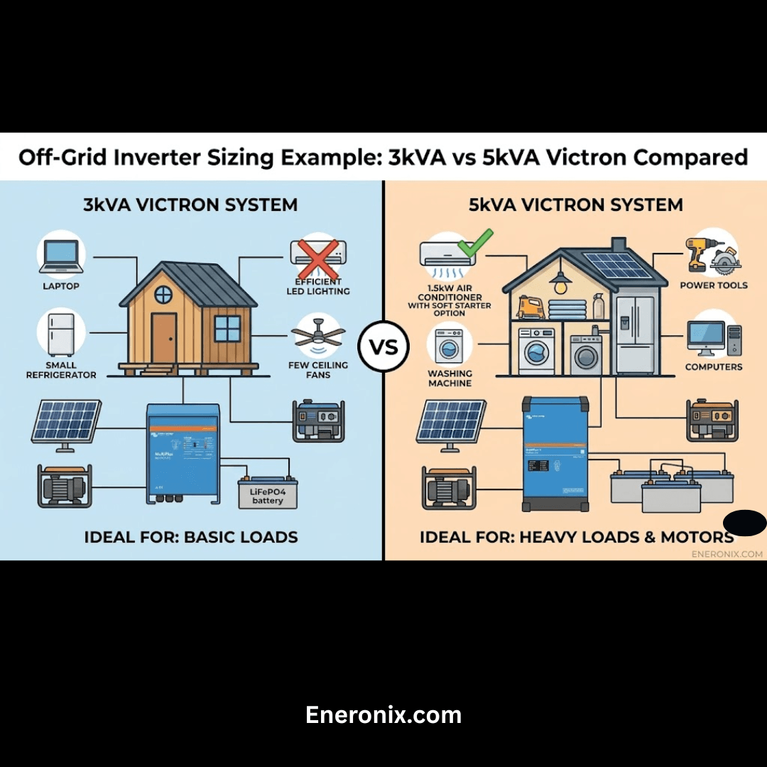
The inverter’s margin is tighter because the Multiplus-II 48/3000 is correctly sized to the load. A 5kVA model would serve the same load at 39 percent utilization, which produces lower partial load efficiency and higher standby losses without any meaningful improvement in surge capability for this load profile.
The 15 percent continuous rating margin is adequate for this installation because the simultaneous continuous load figure of 1,950W already represents full occupancy with the air conditioner running, which is the peak demand scenario rather than the average. During most operating hours the air conditioner will be off, the actual simultaneous load will be 750W, and the inverter will be operating at 25 percent of its rated continuous output, well within its thermal comfort zone.
Step 2: Surge Rating Verification
The surge rating check is where this worked example diverges from a clean pass-through, and it is the check that the real-world scenario in the introduction failed silently for six weeks before the problem became visible. The largest motor load in this system is the 1.5kW air conditioner compressor. Applying the inrush factor from Post #8:
Surge Demand = Motor Running Power x Inrush Factor
Surge Demand = 1,500W x 6 = 9,000W for up to 500 milliseconds
Surge Rating Verification:
Air conditioner running power = 1,500W

Inrush factor = 6x

Surge demand = 9,000W for up to 500ms

Candidate surge rating = 5,500VA for 3ms

Result -> FAIL — insufficient magnitude and duration
Two resolution paths exist, and the choice between them depends on the client’s budget, the installation timeline, and the long-term reliability priorities for the system.
Resolution Path A: Soft Starter on the Air Conditioner
A soft starter is an electronic device fitted to the compressor motor that ramps the motor voltage gradually at startup rather than applying full voltage instantaneously. This reduces the inrush current from 6x running current to approximately 2 to 3x, bringing the surge demand down to 3,000 to 4,500W. Against the Multiplus-II 48/3000’s 5,500VA surge rating, a 3x inrush with a soft starter produces a surge demand of 4,500W, which the inverter can sustain. The check passes with a soft starter fitted.
Soft starters for residential split air conditioners are available in the 100 to 250 USD range depending on unit capacity and brand. They are fitted to the outdoor compressor unit and are transparent to the inverter, the air conditioner’s control board, and the user. The ongoing benefit extends beyond the inverter compatibility: a soft starter reduces mechanical stress on the compressor at every startup, which extends the compressor’s service life.
Resolution Path B: Upgrade to Victron Multiplus-II 48/5000
The Multiplus-II 48/5000 is rated at 5,000VA continuous output and 9,000VA surge for up to 3 milliseconds. Against the 9,000W surge demand at 6x inrush, the surge magnitude check passes exactly at the rated limit. At exactly the surge limit with no margin, a compressor in poor condition, a hot day reducing motor efficiency, or a fully loaded motor at the moment of startup could still produce a surge demand that exceeds the 48/5000’s capability.
A soft starter paired with the 48/5000 is the most robust specification, but the incremental cost of the 48/5000 over the 48/3000 is significant and the continuous rating of 5,000VA on a 1,950W load produces a utilization of 39 percent with the partial load efficiency and standby consequences that entails.
Surge Resolution Summary:
Path A: Soft starter + Multiplus-II 48/3000  -> 4,500W vs 5,500VA  -> PASS with margin

Path B: Multiplus-II 48/5000 (no soft starter) -> 9,000W vs 9,000VA -> PASS at limit

Recommended: Path A, margin, compressor life benefit, lower system cost

Remainder of post: verified against Multiplus-II 48/3000 with soft starter
Step 3: Standby Power Verification
With the surge rating resolved through Path A, the standby power check confirms that the Multiplus-II 48/3000’s idle energy consumption is within the phantom load budget established for this system in Post #3.
E_standby = P_standby x 24h

E_standby = 15W x 24h = 360Wh per day

Standby Power Verification:

Published standby power = 15W

Daily standby energy cost = 360Wh

As percentage of daily demand = 7.3%

Post #3 phantom load budget = accounted for in 4,916Wh figure

Result -> PASS
The reference comparison that frames why this matters: a budget inverter at 35W standby would consume 840Wh per day in standby losses alone, representing 17 percent of the daily energy demand and requiring an additional 500Wh of battery capacity and approximately 175W of additional array capacity to sustain across a two-day autonomy period. The 15W standby figure of the Multiplus-II is not a marginal improvement over a budget alternative. It is a system-sizing input that reduces battery and array requirements in a measurable and calculable way.
Step 4: Waveform and Transfer Speed Verification
The waveform and transfer speed checks are the two specifications that the Multiplus-II 48/3000 satisfies by design rather than by configuration. They are included here not because they are uncertain but because they must be explicitly verified on every candidate, and the habit of skipping them on well-known brands is exactly how modified sine wave inverters and slow transfer switches end up in systems where they cause damage.
The Multiplus-II 48/3000 produces a pure sine wave output with a total harmonic distortion of less than 3 percent at full rated load. Every load category in this system, the air conditioner compressor motor, the refrigerator compressor, the variable speed ceiling fans, the laptop power supplies with active PFC circuits, and the LED lighting drivers, requires pure sine wave input for correct and safe operation.
Waveform and Transfer Speed Verification:

Output waveform = pure sine wave, THD < 3%

Load categories requiring PSW = compressor motors, PFC devices, VFDs, LED drivers

Result — waveform -> PASS

Transfer switch time  = < 20 milliseconds (internal relay)

Sensitive loads in system = computers, variable speed fans

Transfer time requirement = < 20 milliseconds

Result — transfer speed -> PASS
The transfer speed check is where lower-cost alternatives to the Multiplus-II consistently fail on systems with computers and variable speed drives. A standalone inverter paired with a separate electromechanical transfer switch typically achieves transfer times of 80 to 200 milliseconds, which exceeds the hold-up time of active power supply circuits in computers and variable speed fan controllers. The Multiplus-II’s internal electronic transfer relay achieves sub-20 millisecond transfer consistently, which is why the integrated inverter-charger architecture is the correct specification for any system with these load types regardless of the cost premium over a standalone inverter and separate transfer switch.
Step 5: Voltage Window Configuration
The voltage window configuration check converts the inverter from a correctly specified device into a correctly configured one. The Multiplus-II 48/3000 has an adjustable low voltage cutoff range of 38 to 48V and an adjustable high voltage cutoff to 64V. Both must be set to coordinate with the BMS protection thresholds and the MPPT controller’s absorption voltage without conflict.

The voltage setpoints for this 48V LiFePO4 system are derived from the battery chemistry parameters and BMS protection thresholds established in Post #8, and from the MPPT controller absorption voltage established in Post #7. All three must sit in a coordinated hierarchy without overlap:
Voltage Setpoint Hierarchy (48V LiFePO4, 16-cell pack):

MPPT absorption voltage = 56.0V to 58.4V  (3.50V to 3.65V per cell)

Inverter high voltage cutoff = 58.0V (3.625V per cell)

BMS high voltage protection = 58.4V to 59.2V  (3.65V to 3.70V per cell)

BMS low voltage protection = 44.0V to 44.8V  (2.75V to 2.80V per cell)

Inverter low voltage cutoff = 44.0V (2.75V per cell)

Battery practical discharge end = 44.8V (2.80V per cell under load)
The low voltage cutoff at 44.0V sits at the bottom of the BMS low voltage protection range. This configuration allows the inverter to disconnect the AC output at the same threshold where the BMS would otherwise intervene, preventing the BMS latching into a protected state that requires manual recovery. The 44.0V setting accesses the full usable capacity of the LiFePO4 pack without triggering the BMS protection layer in normal operation.
The high voltage cutoff at 58.0V sits below the BMS high voltage protection threshold and within the upper end of the MPPT controller’s absorption voltage range. This ensures the inverter does not interpret a fully charged battery at absorption voltage as an overvoltage condition. The hierarchy is clean: the MPPT controller charges to absorption voltage, the BMS monitors cell-level voltages and applies CVL limiting if any cell approaches its maximum, and the inverter’s high voltage cutoff sits above the normal operating range as a last-resort protection layer.
Voltage Window Configuration Verification:
Low voltage cutoff setting = 44.0V -> above BMS LVP, full capacity access -> PASS

High voltage cutoff setting = 58.0V -> below BMS HVP, above MPPT absorption -> PASS

Setpoint hierarchy = MPPT absorption < Inverter HVC < BMS HVP  -> PASS

Result -> PASS — all three setpoints coordinated
Step 6: AC Charging and Generator Integration
The AC charging configuration check establishes whether the Multiplus-II 48/3000 can correctly manage battery charging from a generator backup source without overloading the generator. The scenario for this installation is a 5kVA backup generator serving the full 1,950W simultaneous continuous load while simultaneously charging the battery bank.
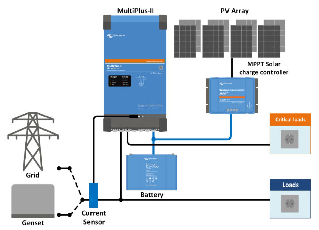
Available Charging Power = Generator Rated Output - Continuous Load

Available Charging Power = 5,000W - 1,950W = 3,050W

Available Charging Current = Available Charging Power / AC Voltage

Available Charging Current = 3,050W / 230V = 13.3A
The Multiplus-II 48/3000 has a maximum AC charging current of 35A, which at 230V represents a maximum charging power of 8,050W. Left at its maximum setting, the inverter-charger would attempt to draw 35A of charging current plus the 1,950W load current simultaneously from the generator, producing a combined demand of approximately 10,000W against the generator’s 5,000W rated output. The generator’s automatic voltage regulator would collapse under this demand, producing a voltage dropout that trips the inverter-charger on low AC input voltage.
The correct AC input current limit setting caps the total current the Multiplus-II draws from the generator, covering both the load passthrough current and the charging current simultaneously:
AC Input Current Limit = Generator Rated Output / AC Voltage

AC Input Current Limit = 5,000W / 230V = 21.7A  ->  set to 21A
At 21A AC input limit, the Multiplus-II manages the distribution of available generator current between the continuous load and battery charging automatically. When the full 1,950W load is running, approximately 8.5A is consumed by the load passthrough and 12.5A remains available for charging, delivering approximately 2,875W of charging power to the battery. When load demand drops, more current is automatically redirected to battery charging up to the 21A input limit.
AC Charging and Generator Integration Verification:
Generator rated output = 5,000W

Continuous load = 1,950W

Available charging power = 3,050W at 13.3A

Multiplus-II max charging = 35A  (more than sufficient)

AC input current limit setting  = 21A  (caps total generator demand)

Result -> PASS , requires AC input limit correctly programmed
Step 7: BMS Communication and Cerbo GX Architecture
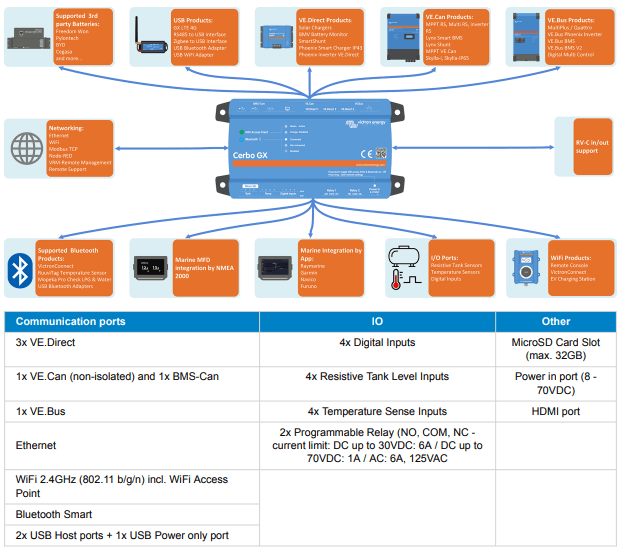
The BMS communication check is the final verification step, and it is the one that most commonly reveals a missing component in the system specification rather than a failing specification in the candidate inverter. The Victron Multiplus-II 48/3000 does not communicate directly with the battery BMS. It communicates with the Victron Cerbo GX, which serves as the system’s communication hub, aggregating data from the BMS, the MPPT charge controllers, and the inverter-charger into a single coordinated control architecture. The Cerbo GX is not an optional monitoring accessory. It is a required functional component of the BMS communication chain on any Victron system where dynamic charge limiting is needed.
The communication architecture for this system is as follows. The battery BMS communicates its CVL and CCL parameters via CAN bus to the Cerbo GX. The Cerbo GX receives these parameters, translates them into VE.Can protocol, and relays them simultaneously to the Multiplus-II inverter-charger and the SmartSolar MPPT 150/60 charge controller. Both charging devices receive the same dynamic charge limits in real time and adjust their output voltage and current accordingly.
Complete BMS Communication Architecture:
Battery BMS -> CAN bus -> Cerbo GX

Cerbo GX -> VE.Can -> Multiplus-II 48/3000

Cerbo GX -> VE.Can -> SmartSolar MPPT 150/60

Cerbo GX -> VE.Bus -> Multiplus-II (charge state coordination)

Cerbo GX -> Remote -> VRM Portal (optional monitoring)
For systems using Pylontech batteries, the Pylontech CAN protocol requires a VE.Can to CAN bus adapter cable between the battery BMS and the Cerbo GX. This adapter must be explicitly specified and the Cerbo GX firmware must be on a version that supports the Pylontech protocol variant. This verification must be performed against the specific battery model being used, not just the Pylontech brand generally.
On systems where the Cerbo GX is not specified or is omitted for cost reasons, the Multiplus-II charges the battery on its programmed fixed voltage setpoints without any dynamic input from the BMS. If a cell group has drifted high due to imbalance, the pack will continue charging until the terminal voltage reaches the programmed absorption setpoint, and that high-drifting cell group will be overcharged in the process. This is not a theoretical risk. It is the normal consequence of omitting the Cerbo GX from a Victron lithium battery system, and it occurs on every charging cycle where any cell imbalance exists in the pack.
For the full treatment of CVL and CCL dynamic charge limiting and the consequences of operating without BMS communication, refer to our engineering posts on CVL, CCL, and DCL dynamic battery limits in real-time systems and BMS-inverter communication protocols in modern solar systems.
Complete Selection Summary and Field Failure Modes
Every verification step in the seven-step selection framework has now been completed against the Victron Multiplus-II 48/3000/35-32 for this specific installation. The results are summarized in the table below. The surge rating failure and its resolution through Path A are documented explicitly so the design decision is traceable from requirement to resolution.
| Parameter | Required / Calculated | Multiplus-II 48/3000 | Result |
| Continuous rating | 2,600W minimum | 3,000VA rated | PASS — 15% |
| Surge (no soft starter) | 9,000W / 500ms | 5,500VA / 3ms | FAIL |
| Surge (with soft starter) | 4,500W / 500ms | 5,500VA / 3ms | PASS — 22% |
| Standby power | Within phantom budget | 15W / 360Wh/day | PASS — 7.3% |
| Output waveform | Pure sine wave | PSW, THD < 3% | PASS |
| Transfer switch time | < 20ms | < 20ms internal | PASS |
| Low voltage cutoff | 44.0V | Adj. 38 to 48V | PASS — 44.0V |
| High voltage cutoff | 58.0V | Adj. to 64V | PASS — 58.0V |
| AC input current limit | 21A for 5kVA gen | 35A maximum | PASS — set 21A |
| BMS communication | CVL/CCL via Cerbo GX | Via Cerbo GX + VE.Can | PASS — req. Cerbo |
The complete verified system specification now includes every active component from array to load: 6 x 400W panels in 3S2P configuration, Victron SmartSolar MPPT 150/60, Victron Multiplus-II 48/3000/35-32 with soft starter on the air conditioner, Victron Cerbo GX, and a 48V LiFePO4 battery bank sized to the autonomy requirement from Posts #1 and #2. Every component has been selected through a documented verification process and every specification traces back to a calculation performed earlier in this cluster.
Common Inverter Selection Failure Modes Observed in Field Systems:
1. Surge rating not verified against motor inrush
Cause: selecting inverter on continuous rating alone
Consequence: inverter shuts down on every compressor start
2. Low voltage cutoff set too high
Cause: leaving default or applying conservative estimate without calculation
Consequence: 30 to 40% of battery capacity unused, chronic autonomy shortfall
3. AC input current limit not programmed for generator capacity
Cause: leaving limit at maximum rated value
Consequence: generator overload, AVR collapse, system fault on every charge cycle
4. Cerbo GX not specified
Cause: treating it as optional monitoring accessory
Consequence: BMS communication absent, systematic overcharge risk
5. Inverter sized to array STC rating rather than simultaneous continuous load
Cause: confusing energy sizing with power sizing
Consequence: chronic partial load, high standby losses, poor efficiency
6. Modified sine wave inverter on system with VFDs or PFC loads
Cause: cost reduction without load compatibility analysis
Consequence: overheating and accelerated degradation of motors and PFC supplies
Conclusion
The worked example in this post produced one non-trivial finding: the Victron Multiplus-II 48/3000’s surge rating is insufficient for a 1.5kW air conditioner compressor at full inrush without a soft starter. That finding is not a flaw in the candidate inverter and it is not a flaw in the system design. It is the selection framework working correctly, surfacing an incompatibility at the design stage where it costs a soft starter to resolve rather than at commissioning where it costs a callback, a client relationship, and the time to diagnose a failure that produces no fault code and no damaged component.
The six field failure modes documented in Section 9 share the same root cause as every failure mode documented in Post #7 for MPPT controller selection: a verification step was omitted. The surge rating was not checked. The low voltage cutoff was not calculated. The Cerbo GX was not specified. Each omission is a decision, and the framework in this post is what makes each of those decisions visible before they become field failures.
The complete system specification is now documented from array to load across nine posts. Every active component has a verified selection and every specification traces back to a calculation. In the next post we move to DC wiring, cable sizing, and fusing, applying the same engineering discipline to the conductors and protection devices that connect every component we have specified so far.
For the complete inverter selection theory, load audit methodology, and phantom load accounting that this worked example builds on, refer to our engineering guides on how to do a proper load audit before sizing an off-grid system, how to account for phantom loads and standby power in off-grid energy budgets, and how to select and size an off-grid inverter.

I am Engr. Ubokobong Ekpenyong, a solar specialist and lithium battery systems engineer with over five years of hands-on experience designing, assembling, and commissioning off-grid solar and energy storage systems. My work focuses on lithium battery pack architecture, BMS configuration, and system reliability in off-grid and high-demand environments.