Introduction
Here is the failure pattern that generates more client callbacks than any other in residential off-grid installation. The system was commissioned, the battery was correctly sized, the array was correctly sized, and the inverter was selected by matching its continuous rating to the average daily load. Everything checked out on paper. Then the client turned on the air conditioner on the first hot morning. The inverter tripped on overload protection. They reset it, tried again, and it tripped again. The installer came back, checked everything, found no fault, and could not explain why a correctly sized system was failing on a load that was well within the inverter’s rated continuous output.
The explanation is that the air conditioner compressor’s startup inrush current, typically five to six times its running current for a fraction of a second, exceeded the inverter’s surge rating. The continuous rating was matched. The surge rating was never checked. One number out of three was missing from the selection process, and that one omission produced a system that could not serve its primary load.
Inverter selection is a three-number problem: continuous rating, surge rating, and standby power consumption. Getting all three right is what separates a system that performs reliably under every operating condition from one that works in the laboratory and fails in the field. This post works through all three, plus the voltage architecture, waveform quality, battery compatibility, and communication requirements that complete the selection.
Continuous Rating: Matching the Inverter to the Real Load
The continuous power rating is the specification that defines the maximum AC output the inverter can sustain indefinitely without thermal protection activating. It is the primary sizing constraint, and the first rule of applying it correctly is that the design target is not the inverter’s rated continuous output but 70 to 80 percent of it. An inverter running continuously at 100 percent of its rated output is operating at its thermal design limit.
Component junction temperatures are at their maximum, thermal protection margins are exhausted, and any additional demand from a load switching on will either trigger a protection shutdown or accelerate degradation of the switching transistors. An inverter running at 75 percent of its rated continuous output has thermal headroom, handles load transients without protection events, and delivers its rated service life.

The continuous load figure the inverter must be sized to is not the total installed load capacity of the system. It is the maximum power all loads that could realistically be running simultaneously will draw at any given moment. For the worked system running through this cluster, the simultaneous continuous load profile is as follows: refrigerator at 150W, lighting at 120W, four ceiling fans at 200W, television and satellite at 180W, and laptop and device charging at 100W. The total simultaneous continuous load under normal occupied evening conditions is 750W. Adding the air conditioner at 1,200W running brings the peak simultaneous continuous load to 1,950W.
At a design target of 75 percent utilization, the minimum inverter continuous rating is:
I_continuous_rating = Continuous Load / Design Utilization Factor
I_continuous_rating = 1,950W / 0.75 = 2,600W
Minimum inverter continuous rating: 2,600W
Recommended selection: 3,000W continuous rated inverter
A 3,000W continuous rated inverter serving 1,950W of simultaneous load operates at 65 percent of rated output, which is comfortably within the thermal design envelope and leaves headroom for load additions and surge events.
Why Matching the Inverter to the Solar Array Is a Design Error
The inverter continuous rating must be sized to the load, not to the solar array STC rating. The array is sized to deliver the daily energy the loads consume, accounting for irradiance, derating, and charge efficiency. The inverter is sized to deliver the instantaneous power the loads demand at any given moment. These are different physical quantities with different sizing equations:
P_inverter = Simultaneous Continuous Load / Design Utilization Factor
P_array = E_daily / (PSH x Derating x η_charge)
These are independent equations. One does not constrain the other.
A 2,400W array serving a system with 1,950W of simultaneous continuous load does not require a 2,400W inverter. On a system with a 5,000W array serving a 1,200W continuous load, matching the inverter to the array produces a 5,000W inverter operating at 24 percent utilization with high standby losses and poor partial load efficiency every hour of the day. On a system with a 2,000W array serving a 3,500W continuous load at night from battery storage, the same logic produces a 2,000W inverter that cannot serve the load at all.
For the load audit methodology and simultaneous load profiling that feeds the inverter sizing calculation, refer to our engineering guide on how to do a proper load audit before sizing an off-grid system.
Surge Rating: Why Motor Starts Define the Peak Requirement
The surge rating is the specification that determines whether the inverter can actually start the largest motor load in the system, and it is the check that the worked example in the introduction failed. When an AC induction motor starts from rest, the rotor is stationary and presents near-zero impedance to the incoming AC supply. The motor draws a large inrush current until the rotor accelerates to near-synchronous speed and back-EMF builds up to limit the current to its steady-state running value. This inrush current is typically three to six times the motor’s rated running current, lasts for 100 to 500 milliseconds, and places a brief but intense demand on the inverter’s output stage.
Surge Demand (W) = Motor Running Power (W) x Inrush Factor
Example: 1.5kW air conditioner compressor, inrush factor 6x
Surge Demand = 1,500W x 6 = 9,000W for 100 to 500 milliseconds
A 3,000W continuous rated inverter must sustain 9,000W for up to 500 milliseconds to start this compressor successfully. Whether it can do so depends on its surge rating and its internal topology. The inverter topology is the specification that determines how long the surge can be sustained and how the unit behaves when surge demand is at the edge of its capability.
Low-frequency inverters use a large toroidal transformer on the output stage. The transformer’s magnetic core stores energy and releases it during transient demand peaks, which allows the inverter to sustain surge currents well beyond its continuous rating for several seconds. A quality LF inverter rated at 3,000W continuous can typically sustain 9,000W or more for 5 to 10 seconds, which comfortably covers even the most stubborn compressor start on a heavily loaded motor. The trade-off is weight, size, and slightly lower peak efficiency compared to HF designs.
High-frequency transformerless inverters are lighter, more compact, and typically achieve higher peak efficiency than LF designs, but their surge capability is constrained by the output switching transistors rather than transformer core energy storage. A quality HF inverter rated at 3,000W continuous can typically sustain 150 to 200 percent of rated output for 20 to 200 milliseconds, which is sufficient for most residential motor starts but may be marginal on large compressors or pump motors with high load inertia.
Inverter Topology Surge Reference:
LF transformer-based -> 200 to 300% surge, sustained 5 to 10 seconds, heavier
HF transformerless -> 150 to 200% surge, sustained 20 to 200ms, lighter
High inrush loads -> specify LF topology or verify HF surge duration explicitly
Soft starter benefit -> reduces inrush from 6x to 2 to 3x, enables HF on heavy motors
Standby Power and Partial Load Efficiency
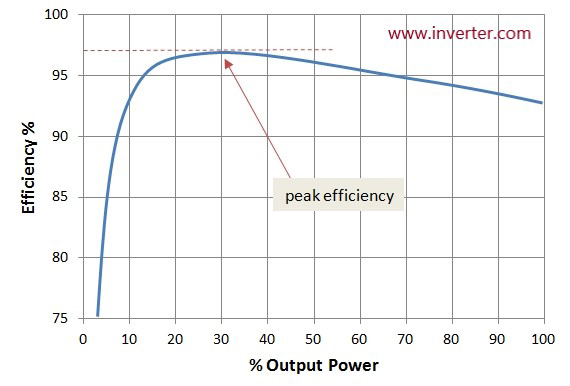
Standby power and partial load efficiency are the two specifications that determine how much energy the inverter costs the battery every day simply by existing in the system. The inverter’s nameplate efficiency figure is measured at peak output, which is the operating condition the inverter spends the least time in during a typical residential day. The conditions it spends the most time in, standby with no load and partial load during light use periods, are where the energy losses are largest relative to the useful work being done.
Standby power is the continuous draw the inverter places on the battery when it is energized but serving no load. This figure ranges from 10W on efficient modern inverter-chargers to 35W or more on older or lower-quality units.
E_standby = P_standby x 24h
Example A: 15W standby inverter
E_standby = 15W x 24h = 360Wh per day
Example B: 35W standby inverter
E_standby = 35W x 24h = 840Wh per day
The 480Wh daily difference between these two examples is not trivial. At the system’s 4,916Wh daily demand figure, a 35W standby inverter consumes 17 percent of the daily energy budget simply maintaining its own readiness. At a battery DoD of 80 percent on a LiFePO4 bank, that standby loss alone requires approximately 600Wh of additional battery capacity to sustain across a two-day autonomy period.
Partial load efficiency compounds the standby problem during the hours when light loads are connected. Most inverters achieve their published peak efficiency at 50 to 80 percent of rated continuous output. At 10 to 20 percent of rated load, which is typical during morning and late evening periods, inverter efficiency on quality units drops to 88 to 93 percent and on budget units to 80 to 86 percent.
E_loss = P_load x t_partial x (1/η_partial – 1)
Example: 300W load for 6 hours at 90% partial load efficiency
E_loss = 300W x 6h x (1/0.90 - 1) = 1,800Wh x 0.111 = 200Wh additional loss
Inverter Efficiency and Standby Reference by Quality Tier:
Premium (Victron, SMA, Fronius) -> standby 10 to 15W, partial load η 92 to 95%
Mid-tier -> standby 15 to 25W, partial load η 88 to 92%
Budget -> standby 25 to 35W, partial load η 80 to 87%
Peak efficiency (all tiers) -> typically at 50 to 80% of rated continuous output
For the phantom load accounting methodology that captures inverter standby and partial load losses in the system energy budget, refer to our engineering guide on how to account for phantom loads and standby power in off-grid energy budgets.
Pure Sine Wave vs Modified Sine Wave
The waveform quality specification is the one inverter selection criterion that admits no compromise on any system serving mixed residential or commercial loads. Pure sine wave output is not a premium feature. It is the minimum acceptable specification for any inverter connected to loads that include variable speed motor drives, devices with active power factor correction circuits, electronic ballasts, audio equipment, medical devices, or any load with a microcontroller-based power supply.
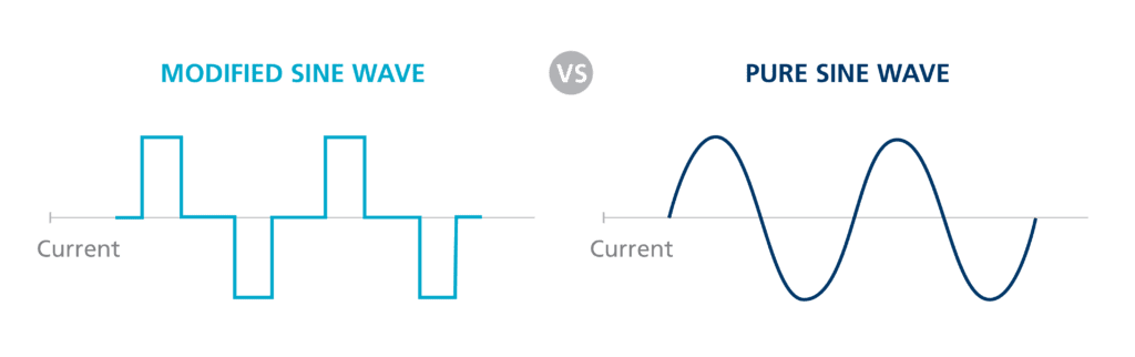
The modified sine wave is not a sine wave. It is a stepped DC waveform that switches between positive, zero, and negative voltage levels at line frequency, producing a rectangular approximation with a total harmonic distortion of 40 to 45 percent, compared to less than 3 percent for a quality pure sine wave inverter. In inductive loads such as motor windings and transformer primaries, harmonic currents produce eddy current and hysteresis losses that manifest as heat. A motor running on a modified sine wave output runs hotter than the same motor on a pure sine wave supply at the same mechanical load, which accelerates insulation degradation and shortens motor service life.
Active power factor correction circuits, found in virtually every modern laptop power supply, LED driver, variable speed drive, and high-efficiency appliance, are designed to operate on a sinusoidal input voltage. When the input voltage is a modified sine wave, the PFC circuit’s control loop attempts to shape the input current to match a waveform that does not exist, producing erratic switching behavior, overheating of the PFC inductor, and in some cases damage to the PFC control IC.
| Load Type | Pure Sine Wave | Modified Sine Wave | Risk Level |
| VFDs / motor drives | Full compatibility | Malfunction / damage | Critical |
| Active PFC devices | Full compatibility | Overheating / damage | Critical |
| Compressor motors | Normal operation | Accelerated wear | High |
| Audio / medical | Full compatibility | Interference / damage | High |
| Resistive loads | Full compatibility | Acceptable | Low |
The rule I apply without exception is pure sine wave output on every off-grid system regardless of load composition. The cost premium for pure sine wave output on modern inverters in the 1kVA to 10kVA range is negligible relative to the replacement cost of a single compressor motor or variable speed drive damaged by harmonic distortion.
Transfer Switch Speed and Generator/Grid Integration
The transfer switch is the mechanism that moves connected loads between the inverter output and an external AC source, and the speed at which it completes that transition determines which load categories remain stable through the switchover and which ones interrupt, reset, or fault. In a break-before-make transfer switch, which is the most common architecture in standalone inverter-charger units, the load is briefly disconnected from both sources during the transition. The duration of this disconnection is the transfer time.

Computers and servers with active power supplies and capacitive hold-up circuits can sustain an input interruption of 20 to 50 milliseconds before the hold-up capacitors discharge below the point where the power supply can maintain output regulation. Variable speed drives with DC bus capacitors have similar hold-up times in the 15 to 30 millisecond range. UPS systems on the load side of the inverter have their own transfer time requirements for handoff to battery, which must be shorter than the inverter’s own transfer time to remain in an always-online condition.
Transfer Switch Speed Reference by Load Category:
Computers and servers -> require < 20ms transfer time
Variable speed drives -> require < 20ms transfer time
UPS systems downstream -> require < 10ms for seamless handoff
Lighting and resistive loads -> tolerate 50 to 200ms without interruption
Motor loads -> tolerate brief interruption, may require restart
The generator sizing rule for inverter-charger systems integrating a generator backup is that the generator must be capable of supplying both the inverter-charger’s maximum AC charging input power and the continuous load simultaneously. A 5kVA inverter-charger with a 3,500W maximum charging input serving 2,000W of continuous load requires a generator rated at a minimum of 5,500W to supply both simultaneously without the automatic voltage regulator collapsing under the combined demand.
Voltage Architecture: Why 48V Is the Correct Choice Above 2kVA
The system voltage decision, whether to build the DC battery and inverter architecture at 12V, 24V, or 48V, is one that most installers make by default rather than by calculation. The correct approach is to derive the system voltage from the DC current it must carry at the required power level, and the formal equation that makes this explicit is:
I_DC = P_AC / (V_DC x η_inverter)
Where:
I_DC = DC current drawn from battery at rated AC output (A)
P_AC = AC output power (W)
V_DC = battery system voltage (V)
η_inverter = inverter efficiency as decimal (e.g., 0.92)
Applying this to a 5,000W AC output at 92 percent inverter efficiency across the three common system voltages:
At 12V: I_DC = 5,000W / (12V x 0.92) = 5,000 / 11.04 = 453A
At 24V: I_DC = 5,000W / (24V x 0.92) = 5,000 / 22.08 = 226A
At 48V: I_DC = 5,000W / (48V x 0.92) = 5,000 / 44.16 = 113A
| System Voltage at 5kW Output | Practical Consequence |
| 12V — 453A DC | 240mm² cable, industrial busbars, 500A+ fusing impractical for residential |
| 24V — 226A DC | 120mm² cable, heavy busbars — marginal above 3kW |
| 48V — 113A DC | 35mm² cable, 125A ANL fuse, standard M8 terminals — practical and cost-effective |
At 12V, a 5,000W inverter draws 453A from the battery. Carrying 453A continuously requires DC cable with a cross-section of at least 240mm² for a 1-metre run — a cable the diameter of a garden hose. At 48V, the same output draws 113A, carried safely by 35mm² cable, fused with a standard 125A ANL fuse. The current at 48V is one-quarter of the current at 12V for the same output power. Every cable loss, every connection resistance, every fuse rating, and every busbar cross-section scales with current. The threshold I apply is that any system with an inverter rated above 2kVA should be designed at 48V system voltage.
For the full treatment of BMS communication protocol compatibility and charge algorithm configuration, refer to our engineering guides on how MPPT charge controllers work and how to select the right one and how to size and select an MPPT controller for a specific system.
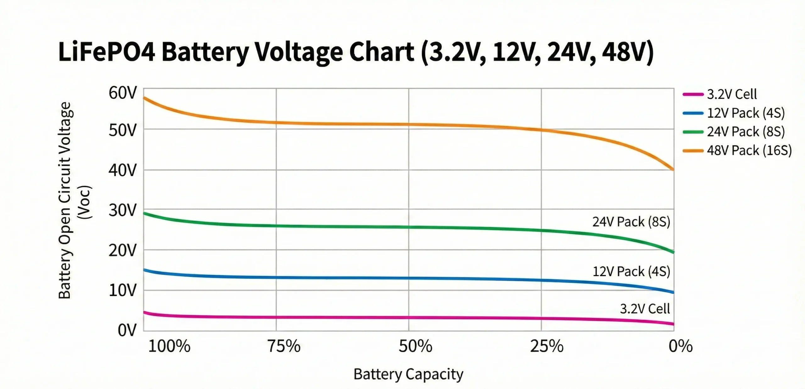
Input Voltage Window and Battery State of Charge Management
The inverter’s input voltage window defines the range of DC battery voltage over which it will operate, and the two boundaries of that window must be configured correctly for the specific battery chemistry and capacity before the system is commissioned. Incorrect cutoff settings are one of the most common sources of reduced system autonomy and BMS protection lockouts on lithium battery installations.
The low voltage cutoff is the DC input voltage below which the inverter disconnects its AC output to prevent further battery discharge. On a 48V LiFePO4 system, the correct low voltage cutoff must be set above the BMS’s low voltage protection threshold but below the battery’s usable discharge endpoint. A LiFePO4 cell reaches its practical discharge endpoint at approximately 2.8V per cell under load, which corresponds to 44.8V on a 16-cell 48V pack. The inverter’s low voltage cutoff should be set at 44 to 45V, accessing the full usable capacity of the battery while stopping discharge before the BMS protection threshold is reached.
LiFePO4 48V System Voltage Cutoff Reference:
a. Inverter low voltage cutoff -> 44.0V to 45.0V  (2.75V to 2.81V per cell)
b. BMS low voltage protection -> 44.0V to 44.8V  (2.75V to 2.80V per cell)
c. Inverter cutoff rule -> must be above BMS threshold to prevent lockout
d. Inverter high voltage cutoff -> 58.0V to 59.0V  (3.625V to 3.69V per cell)
e. BMS high voltage protection -> 58.4V to 59.2V  (3.65V to 3.70V per cell)
f. Inverter high cutoff rule -> must be below BMS threshold with margin
Setting the low voltage cutoff too high, for example at 48V rather than 44V on a 48V nominal pack, prematurely disconnects the AC output before the battery’s usable capacity is accessed. A 48V cutoff leaves approximately 30 to 40 percent of the battery’s usable capacity untouched every discharge cycle, and is one of the most common sources of reported autonomy shortfalls on newly commissioned lithium systems where the battery bank appears undersized but is actually incorrectly configured.
Setting the low voltage cutoff too low, below the BMS’s low voltage protection threshold, creates a different failure mode. The BMS disconnects the battery entirely rather than the inverter disconnecting its AC output in a controlled manner, the system goes dark without warning, and the BMS latches in a protected state that requires manual intervention or a charge source to reset.
Inverter-Charger Integration and Communication Architecture
The decision between a standalone inverter paired with a separate battery charger and transfer switch versus an integrated inverter-charger is an architecture decision with direct consequences for transfer switch speed, BMS communication complexity, charge coordination, and the number of independent points of failure in the system’s power conversion chain.
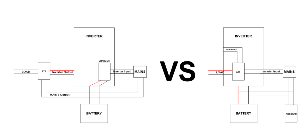
A standalone inverter handles DC to AC conversion only. When an external AC source becomes available, a separate automatic transfer switch is required to disconnect the inverter output and connect the loads to the external source. A separate battery charger then handles AC to DC conversion to recharge the battery. This architecture requires three independent devices, three sets of protection and communication interfaces, and a transfer switch whose speed is determined by its own relay characteristics rather than by the inverter’s internal control logic. Transfer times on standalone inverter plus separate transfer switch architectures are typically 50 to 200 milliseconds, which exceeds the tolerance of computers, variable speed drives, and other sensitive electronics.
An integrated inverter-charger performs both DC to AC inversion and AC to DC charging within a single unit, and the transfer between inverter output and external AC source is handled by an internal relay under direct control of the inverter-charger’s main processor. This allows transfer times below 20 milliseconds on quality units. The internal architecture also means the charging current to the battery is managed by the same firmware that manages the inverter output, allowing the unit to coordinate battery charging rate with the MPPT controller’s simultaneous charging contribution through a single shared BMS communication interface.
The Victron Multiplus and Quattro inverter-charger families represent the integrated architecture at its most fully developed implementation. The Multiplus is a single AC input, single AC output inverter-charger. The Quattro adds a second AC input, allowing independent connection of grid and generator with automatic source selection and priority management. Both units communicate with the battery BMS via VE.Can, coordinate with MPPT charge controllers via VE.Net, and expose the full system state to monitoring via Victron’s Cerbo GX communication hub.
For the BMS communication protocol and charge coordination methodology that the inverter-charger architecture depends on, refer to our engineering guides on how MPPT charge controllers work and how to select the right one and how to size and select an MPPT controller for a specific system.
Parallel and Three-Phase Configurations
The single-unit inverter architecture has a natural power ceiling defined by the largest continuous rating available in a given product family. For the Victron Multiplus-II, that ceiling is 15kVA per unit. When the continuous load requirement exceeds what a single unit can deliver, or when the installation requires three-phase AC output, multi-unit configurations are the correct engineering response.
Parallel configuration connects two or more identical inverter-charger units on a shared single-phase AC bus, each unit contributing its rated continuous output to the combined load. Two Victron Multiplus-II 5kVA units in parallel deliver a combined 10kVA continuous output on a single phase. The critical discipline in parallel configuration is load distribution: the combined system should be designed so that no single unit operates above its individual continuous rating under any foreseeable load scenario.
If two 5kVA units are sharing a 9kVA continuous load and one unit fails, the remaining unit faces 9kVA against a 5kVA rating and will immediately trip on overload protection. Correct parallel design sizes the combined system so each unit carries no more than 70 to 75 percent of its individual continuous rating under maximum expected load, which preserves the redundancy value of the parallel architecture.
Three-phase configuration synchronizes three identical inverter-charger units across the three phases of a three-phase AC distribution system. This architecture is required on installations serving three-phase motor loads, three-phase distribution boards, or facilities where the utility connection is three-phase and the off-grid system must replicate that supply structure. Each unit handles one phase independently but synchronizes its output frequency and phase angle with the other two units through the inter-unit communication link.
Multi-Unit Configuration Reference:
Parallel (single-phase) -> identical units, shared AC bus, each within individual rating

Three-phase -> three identical units, synchronized via inter-unit comms

Unit matching requirement -> same model, same firmware version, same configuration

Redundancy design rule -> each unit at max 70 to 75% of individual continuous rating

Load balancing requirement -> three-phase loads distributed evenly across phases
Phase synchronization in both parallel and three-phase configurations requires that all units are from the same product family, running the same firmware version, and configured identically in terms of voltage setpoints, transfer switch behavior, and BMS communication parameters. Mixing firmware versions across units in a synchronized configuration is a documented source of phase drift, protection conflicts, and charge coordination failures that manifest intermittently rather than as hard faults.
Conclusion
Inverter selection is a three-number problem at its core: continuous rating matched to simultaneous load at 70 to 80 percent utilization, surge rating verified against the largest motor inrush demand in the system, and standby power confirmed against the daily energy budget. Every system that fails on startup, trips under normal load, or drains its battery overnight while serving no useful load has a root cause in one of these three numbers being wrong or missing from the selection process.
The additional specifications covered in this post, waveform quality, transfer switch speed, voltage architecture, input voltage window configuration, BMS communication protocol, and inverter-charger integration, are the configuration layer that determines whether the correctly sized inverter serves its battery system correctly, transfers its loads reliably, and communicates with the BMS in a way that protects cell integrity across thousands of charge and discharge cycles. An inverter with the right continuous rating, the right surge capability, and the right standby figure that charges its LiFePO4 battery on a fixed lead-acid profile without BMS communication is still the wrong inverter for that system.
The DC current equation in Section 6 makes the voltage architecture decision unambiguous for any system above 2kVA. At 5kW output, 12V draws 453A and 48V draws 113A. That four-fold reduction in DC current eliminates an entire category of cable sizing, connection hardware, and fusing complexity. The voltage architecture decision is a calculation, not a preference.
For the complete seven-step worked example applying this framework to a specific Victron Multiplus-II selection, refer to our guide on Off-Grid Inverter Sizing: 3kVA vs 5kVA Victron Multiplus-II — Complete Worked Example.
For the load audit, phantom load accounting, MPPT controller sizing, and BMS communication methodology this post builds on, refer to our engineering guides on how to do a proper load audit before sizing an off-grid system, how to account for phantom loads and standby power in off-grid energy budgets, how MPPT charge controllers work and how to select the right one, and how to size and select an MPPT controller for a specific system.

I am Engr. Ubokobong Ekpenyong, a solar specialist and lithium battery systems engineer with over five years of hands-on experience designing, assembling, and commissioning off-grid solar and energy storage systems. My work focuses on lithium battery pack architecture, BMS configuration, and system reliability in off-grid and high-demand environments.