A textbook 12V off-grid system: 4 100Ah LiFePO4 batteries in parallel, 3000W inverter, proper gauge cable. Light loads worked perfectly. But when the well pump kicked on, the inverter shut down with a low-voltage alarm. Battery bank reading: 13.1V. Inverter input: 10.2V.
The culprit? Voltage drop – 1.5V lost between battery terminals and inverter under 150A surge current. That’s 11.5% of system voltage vanishing into cable resistance and connections. In voltage drop in 12V solar systems, physics doesn’t negotiate. At 48V, that same 1.5V drop would be just 3%. At 12V, it killed the system.
Understanding DC Voltage Drop in Low Voltage Solar Systems
Voltage drop in DC systems follows Ohm’s Law: V = I × R. Every conductor, connector, and contact point has resistance. When current flows through resistance, you lose voltage. What makes this brutal for low voltage DC systems is that power scales linearly with voltage (P = V × I), so delivering the same power at lower voltage requires proportionally higher current.
A 1200W load at 48V draws 25A. That same load at 12V draws 100A – four times the current. But voltage drop isn’t linear with current – it follows I²R losses. Double the current, and you quadruple the heat and voltage drop.
CRITICAL PHYSICS INSIGHT: The power dissipated as heat in your cables and connections follows I²R, not just I × R. A 12V system moving 100A through infrastructure that handles 25A at 48V doesn't experience four times the voltage drop - it experiences sixteen times the drop. The math is unforgiving.
DC Voltage Drop Calculation: Real-World Example
Scenario: 10 feet battery to inverter (20 feet round-trip), 2 AWG copper cable (0.16Ω per 1000 feet = 3.2 milliohms total)
At 48V System (1200W load, 25A):
Voltage drop: V = 25A × 0.0032Ω = 0.08V
Power loss: P = 25² × 0.0032 = 2W
Percentage drop: 0.08V / 48V = 0.17%
At 12V System (same 1200W, 100A):
Voltage drop: V = 100A × 0.0032Ω = 0.32V
Power loss: P = 100² × 0.0032 = 32W
Percentage drop: 0.32V / 12V = 2.67%
The 12V system experiences 16x more heat (32W vs 2W). Cables get warm, copper resistance increases with temperature, and voltage drop worsens under sustained load – climbing from 0.32V to 0.40V or more after 20 minutes.
12V vs 24V vs 48V Solar System Comparison
For a 10-foot cable run with 2% voltage drop target delivering 2400W continuous:
| System Voltage | Current Draw | Required Cable | Cable Cost (10ft) | Voltage Drop | Heat Loss |
| 12V | 200A | 4/0 AWG | $80-120 | 0.24V (2%) | 48W |
| 24V | 100A | 2 AWG | $25-35 | 0.48V (2%) | 12W |
| 48V | 50A | 6 AWG | $15-25 | 0.96V (2%) | 3W |
Cable cost savings at 48V: 70-80% compared to equivalent 12V installation. Factor in connector costs (2/0 lugs are $15-25 each versus $3-5 for 6 AWG), and the savings compound.
Where Voltage Actually Drops: Component-by-Component Analysis
Most people think voltage drop is a “cable problem.” In practice, cables account for only 40-60% of total resistance. The rest hides in connections, protective devices, and overlooked components.
Solar Cable Sizing
Critical mistake: You lose voltage on both positive and negative conductors. A 10-foot cable run is actually 20 feet of copper in the current path. When performing DC voltage drop calculation, failing to account for round-trip distance means you’re off by a factor of two from the start.
At 100A through 4 AWG cable (0.25 milliohms per foot), that 20-foot round trip gives you 5 milliohms × 100A = 0.5V drop just in wire. On a 12V system, that’s 4% gone before any other component.
Crimp Connections and Terminal Resistance

A proper hydraulic crimp adds 0.5-1 milliohm of resistance. A hammer crimper or undersized crimp? 3-8 milliohms – and it degrades over time. At 100A, that poor crimp costs you 0.8V by itself.
Six connection points between battery and inverter (battery terminal, busbar, fuse holder, breaker, inverter lug, ground) can add 3-12 milliohms. At 100A in a 12V system, that’s 0.3-1.2V lost before considering cable resistance.
CASE STUDY: The 4/0 Cable That Wasn't Enough

A frustrated installer called about a 12V system shutting down under any load above 1500W. He'd oversized cable to 4/0 AWG for an 8-foot run - on paper, less than 2% voltage drop at 150A. The inverter was cutting out at 10.6V whenever the microwave ran.

The diagnosis: The cable itself was perfect (0.6 milliohms). But the crimp connections were a disaster. The installer used a hammer-style crimper instead of hydraulic press. Measured resistance: 4-8 milliohms per crimp, with four crimps in the current path.

At 150A, those bad crimps were dropping 3.0-4.5V. Battery terminals showed 13.1V under load, but inverter input saw 9.5-10.1V. The 4/0 cable was doing its job perfectly - the terminations killed the system.

The fix: Re-crimped everything with hydraulic crimper. Resistance dropped to 0.3-0.5 milliohms per connection. Total voltage drop under 150A went from 4.5V to 0.8V. Problem solved.
Fuse Holders: The 5+ Milliohm Surprise

Cheap ANL fuse holders add 5-10 milliohms of resistance each. Two holders (positive and negative) at 100A means 1-2V drop just in protection hardware. Quality Class T fuse holders or DC-rated circuit breakers reduce this to 1-2 milliohms total.
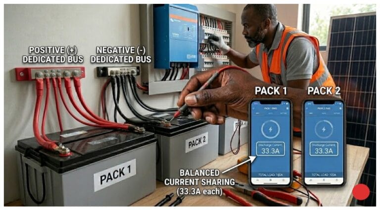
Parallel Battery Wiring and Current Distribution Issues

Four 12V 100Ah batteries in parallel should provide 400Ah capacity at 12V. In practice, parallel battery wiring creates unequal current distribution if not done correctly. The battery closest to the load connection carries more current than the farthest battery – sometimes 40% more.
Common parallel wiring mistake:
connecting batteries in a daisy chain, then taking the load from one end. This creates cumulative resistance through battery interconnects.
Correct method:
use a busbar with equal-length cables from each battery to the busbar, then take the load from the center of the busbar. This ensures balanced current draw and minimizes individual battery stress.
Inverter Low Voltage Cutoff vs BMS Voltage Protection
Here’s the failure mode nobody talks about: your BMS voltage protection measures voltage at the battery terminals. Your inverter low voltage cutoff measures voltage at the inverter input. These are not the same location, and infrastructure resistance creates a gap between them.
Scenario:
Battery voltage (BMS reading): 13.0V
Infrastructure resistance: 15 milliohms
Load current: 150A (inverter surge)
Voltage drop: 15mΩ × 150A = 2.25V
Inverter sees: 13.0V – 2.25V = 10.75V
Inverter cutoff threshold: 11.0V → System shuts down
The BMS never triggers a fault because from its perspective, cell voltage is fine at 13.0V. The inverter shuts down on low voltage protection. The user sees a healthy battery and a tripping inverter, blames the inverter, and never identifies the real problem: infrastructure voltage drop.
BMS Measurement Location Matters
The BMS monitors cell voltage, not load-side voltage. It has zero visibility into what happens downstream after current flows through cables, fuses, breakers, and connections. This measurement gap creates diagnostic blind spots.
INSTALLER TAKEAWAY: Total system voltage drop = cable resistance + connection resistance + internal battery resistance + protective device resistance. You must measure under worst-case load current to identify real-world performance. Resting voltage tells you nothing about infrastructure adequacy.
Solar Battery Voltage Sag Under High Current Draw
Even without infrastructure resistance, solar battery voltage sag occurs due to internal battery resistance. LiFePO4 cells have internal resistance of 0.5-3 milliohms per cell depending on chemistry, temperature, and state of charge.
A 12V LiFePO4 battery (4S configuration) has 4 cells in series. If each cell has 2mΩ internal resistance, total internal resistance is 8mΩ. At 100A draw:
Internal voltage drop: 100A × 0.008Ω = 0.8V
Also Read: Solar System Cable Gauge and Length: How They Affect Performance
Battery terminal voltage during 100A: drops by 0.8V from resting voltage
This is in addition to infrastructure resistance. If your battery sits at 13.2V at rest, terminal voltage under 100A load drops to 12.4V just from internal resistance, before accounting for cables and connections.
Temperature makes this worse. At 0°C, LiFePO4 internal resistance can double or triple. Your system that works fine at 25°C fails at freezing temperatures because cold-weather internal resistance compounds infrastructure voltage drop.
CASE STUDY:
Parallel Battery Bank with Unequal Cable Lengths

A 12V off-grid cabin system with four 100Ah LiFePO4 batteries in parallel worked fine for 30 minutes under moderate load (1200-1500W), then one battery would disconnect and the whole system shut down.

The problem: Three batteries had 18-inch cables to the busbar. The fourth had a 24-inch cable. That 6-inch difference created 0.1 milliohms of imbalance.

The result: Three batteries pulled 35-36A each. The long-cable battery pulled 43-45A. After 25-30 minutes, it hit the BMS temperature cutoff at 45°C while others stayed at 38-40°C.

The fix: Equalized all four cables to 24 inches. Current distribution evened out to within 1-2A. Temperatures stayed balanced. System ran indefinitely at rated load. The "defective" battery was fine - it was just handling a disproportionate share of load.
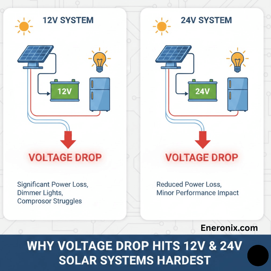
24V Solar System Problems
24V systems reduce current by half compared to 12V, which sounds promising. For a 1200W load, you’re drawing 50A instead of 100A. Voltage drop is halved, and I²R losses drop to one-quarter. On paper, 24V appears to be the sweet spot.
In practice, 24V solar system problems emerge from ecosystem limitations. Component availability is worse than 12V or 48V. Many inverters, charge controllers, and DC loads are optimized for either 12V (legacy automotive/marine) or 48V (modern battery systems). Finding quality 24V equipment often means accepting fewer options or paying premium prices.
24V also inherits scaling problems. For residential off-grid (5-10kW), you’re still dealing with 200-400A surge currents. That still requires 2/0 to 4/0 AWG cable, expensive connectors, and careful construction. You’ve improved over 12V but haven’t escaped the fundamental problem.
The best use case for 24V: mid-size systems (2-4kW continuous) where 12V is clearly inadequate but 48V equipment is overkill or unavailable. Mobile installations like larger RVs, work trucks, or medium-sized boats benefit from 24V if they’re running significant AC loads through an inverter.
12V vs 48V Solar System: The Engineering Reality

The comparison between 12V vs 48V solar system architectures isn’t about preference – it’s about physics and economics.
Cable Cost Savings at 48V
For a 10-foot run at 2% voltage drop target:
12V system (100A continuous): Requires 2/0 AWG ($4-6/foot) = $80-120 for cable alone
48V system (25A continuous): Requires 6 AWG ($0.80-1.50/foot) = $16-30 for cable
Cable cost reduction: 70-80%. Factor in connector costs (2/0 lugs are $15-25 each versus $3-5 for 6 AWG), and the savings compound. For a complete system with battery interconnects, main runs, and branch circuits, 48V infrastructure costs 60-75% less than equivalent 12V.
System Scalability and Future-Proofing
12V systems hit practical limits around 3-4kW continuous (250-300A). Beyond that, you’re into 4/0 AWG cable, specialty high-current connectors, and infrastructure that’s genuinely difficult to work with. Labor costs escalate because everything takes longer and requires specialized tools.
48V systems scale elegantly to 10-15kW (200-300A) using manageable cable sizes and standard components. Even at 300A, you’re using 2/0 to 4/0 cable – the same as a 12V system at 75-100A. The voltage drop percentage stays low, thermal management is reasonable, and the system remains serviceable.
Design Rules for Low-Voltage DC Solar Infrastructure
After diagnosing hundreds of failing 12V systems, these design rules consistently separate functional systems from problematic ones:
- Design for worst-case surge current, not continuous load. Size cables and connections for maximum instantaneous current your system will ever see – inverter peak power, motor starting, compressor startup.
- Target 2% voltage drop for continuous loads, accept 5% for surge loads <60 seconds. Calculate at maximum current. National Electrical Code allows 3% for branch circuits; tighter tolerance provides margin.
- Use hydraulic crimpers, not hammer crimpers. Invest in proper crimping tools. Poor crimps add 3-8 milliohms each and degrade rapidly.
- Minimize connection points. Every connection adds resistance. Direct battery-to-busbar-to-inverter is better than battery-to-disconnect-to-fuse-to-busbar-to-breaker-to-inverter.
- Use quality DC-rated protective devices. Class T fuses or DC-rated breakers. Avoid cheap ANL fuse holders. Resistance matters.
- Install load-side voltage monitoring. Don’t rely solely on BMS voltage readings. Monitor at inverter input to see actual delivered voltage.
- Parallel batteries with equal-length cables to a busbar. Avoid daisy-chain wiring. Take loads from busbar center for balanced current distribution.
- Account for temperature derating. Battery internal resistance increases in cold. If operating below 10°C, add 25-50% margin to voltage drop calculations.
- Torque all connections to specification. Use a torque wrench. Loose connections develop high resistance and overheat.
- Default to 48V for systems >2kW continuous. Physics doesn’t compromise. For residential off-grid, 48V eliminates voltage drop as a design constraint.
Why 48V Systems Avoid Most of This
When you step up to 48V, current for any given power level drops to one-quarter of what you’d see at 12V. A 3000W load that pulls 250A at 12V only draws 62.5A at 48V. That factor-of-four reduction in current translates to a factor-of-sixteen reduction in I²R losses because power dissipation scales with current squared. This isn’t a marginal improvement – it’s a complete transformation.
Cable Sizing at 48V Becomes Trivial
A 5kW inverter (largest typical for home backup) draws 104A at 48V. A 10-foot run with 2 AWG cable – which costs $30-40 and you can bend by hand – gives you about 1% voltage drop. The same 5kW at 12V would draw 417A and require multiple parallel runs of 4/0 cable.
At 48V, you use standard gauge wire, standard lugs, standard crimpers, and everything just works.
Contact Resistance Stops Being Critical
A crimp connection with 1 milliohm of resistance – mediocre but not terrible – drops 0.06V at 62.5A. That’s 0.125% of system voltage. You can get away with slightly imperfect connections and the system still functions reliably.
At 12V, that same 1 milliohm connection at 250A drops 0.25V – 2% of system voltage gone in a single connection point. There’s no forgiveness for mistakes at 12V.
Surge Loads Stay Manageable
Motor starting currents are still 3-5× running current, but the absolute current levels are low enough that standard infrastructure handles them. A well pump that surges to 250A at 12V only surges to 62.5A at 48V. Your 2 AWG cable and properly torqued connections might see 0.15V drop during surge – 0.3% of system voltage.
The inverter’s low-voltage cutoff at 48V is typically around 42-44V, with normal battery voltage from 48V (empty) to 58.4V (full charge). You’ve got 10-16V of working range, so losing 0.15V to surge drop is completely negligible.
Why does my 12V solar system shut down when batteries show plenty of charge?
Your BMS measures voltage at the battery terminals, but your inverter measures voltage at its input. Infrastructure resistance (cables, connections, fuses) creates voltage drop between these points. Under high current loads, battery might read 13V while inverter sees 10.5V, triggering low-voltage cutoff. This is especially severe in 12V systems where high current amplifies I²R losses.
How do I calculate voltage drop for my solar cable sizing?
Use the formula: Voltage Drop = Current × Resistance × 2 (for round trip). Find cable resistance per foot from wire tables, multiply by total one-way distance, multiply by 2, then multiply by maximum current. Divide result by system voltage to get percentage drop. Target <2% for continuous loads, <5% for short surge loads.
Is 24V better than 12V for solar systems?
24V reduces current by half compared to 12V, cutting voltage drop and cable requirements significantly. However, component availability is worse than 12V or 48V. Best use case: medium systems (2-4kW) where 12V is inadequate but 48V is overkill. For residential systems >3kW, 48V is usually superior to 24V.
What causes high resistance in battery parallel connections?
Daisy-chain wiring creates unequal current distribution and cumulative resistance. Proper method: use a busbar with equal-length cables from each battery. Take loads from busbar center. Poor crimp connections add 3-8 milliohms each and degrade over time. Always use hydraulic crimpers, not hammer crimpers.
Why do cheap fuse holders cause voltage drop problems?
Cheap ANL fuse holders can add 5-10 milliohms of resistance each. At 100A in a 12V system, that’s 1-2V lost just in fuse holders. Quality Class T fuse holders or DC-rated breakers reduce this to 1-2 milliohms total. Protective device resistance is often overlooked but accounts for 20-30% of total system resistance.
When should I choose 48V over 12V for my solar battery system?
Choose 48V for any continuous load above 2kW. At 48V, you’ll use 70-80% less expensive cable, achieve <1% voltage drop with manageable wire sizes, and eliminate voltage drop as a design constraint. 12V is suitable for small systems (<1kW), RVs, marine applications, or where you have existing 12V infrastructure. For new residential installations, 48V should be the default.
Conclusion
Voltage drop isn’t abstract electrical theory – it’s the number one cause of failures in 12V and 24V solar battery systems. Lower system voltage creates exponentially higher infrastructure requirements, not linearly higher. Going from 48V to 12V doesn’t just require four times the cable; it requires sixteen times lower resistance in your entire current path because losses scale with I²R.
The BMS can’t protect you against what it doesn’t measure. It monitors cell voltage at battery terminals with zero visibility into downstream voltage after current flows through cables, fuses, and connections. This disconnect between measurement location and actual delivered voltage creates failure modes nearly impossible to diagnose without load-side monitoring.
Design for worst-case current, not nameplate ratings. Cable and connection sizing must handle maximum surge current your system will ever see – motor starting, inverter peak power, cold-weather charging. Size for average loads and your system fails during the 10% of situations where you actually need it.
For residential off-grid or backup power above 2kW continuous, 48V should be your default choice. The improvement over 12V isn’t incremental – it’s transformative. Cable costs drop 70-80%, connection quality becomes less critical, and you’re working with an industry-standard voltage where component selection is broad and prices competitive.
Ready to Design a Reliable Solar Battery System?
Start with proper infrastructure:
- Quality hydraulic crimpers
- DC-rated protective devices
- Cable sized for worst-case surge loads at 2% voltage drop
- Load-side monitoring to measure actual delivered voltage
These practices aren’t expensive relative to system cost, but they’re the difference between a system that works reliably for ten years and one generating service calls every few months.
For installers and system designers: Defaulting to 48V for anything above 2kW eliminates an entire category of problems. You stop fighting voltage drop, stop worrying about perfect crimps, and stop getting calls about mysterious shutdowns. The system just works.
If evaluating an existing 12V or 24V system experiencing unexplained shutdowns, measure voltage under load at multiple points: battery terminals, busbar, inverter input. Use a clamp meter to verify actual current. Check every connection with a milliohm meter. In 80% of cases, voltage drop problems stem from poor connections – inadequate crimps, loose bolts, corroded terminals – not undersized cable.
Voltage drop is physics, and physics doesn’t compromise. You either design infrastructure to handle the current at your chosen voltage, or accept that the system will fail when you need it most. At 12V with high-power loads, infrastructure requirements are brutal. At 48V, requirements are manageable and properly designed systems just work.

I am Engr. Ubokobong Ekpenyong, a solar specialist and lithium battery systems engineer with over five years of hands-on experience designing, assembling, and commissioning off-grid solar and energy storage systems. My work focuses on lithium battery pack architecture, BMS configuration, and system reliability in off-grid and high-demand environments.