I’ve installed enough solar systems to know that most performance complaints trace back to decisions made in the first week of installation, decisions about things that seem trivial at the time. Cable sizing is one of them.
When a homeowner calls eighteen months after commissioning to report that their batteries “never fully charge” or their inverter “keeps shutting down for no reason,” I don’t immediately suspect the panels or the battery cells. I ask about cable runs. How far is the charge controller from the battery bank? What gauge did they use between the inverter and batteries? Can they feel the cables during operation?
Nine times out of ten, the system is bleeding power through undersized or unnecessarily long cables. The panels are working. The batteries are functional. But the electrical infrastructure connecting them is creating losses that compound daily, degrading performance and shortening component life in ways that aren’t immediately obvious until the damage is done.
This isn’t a theoretical concern. In practice, I see 12V systems losing 5-8% of their generated power to cable resistance alone, not because installers are incompetent, but because voltage drop calculations get skipped, cable runs get extended for convenience, and the consequences don’t show up on commissioning day. They show up months later as chronic undercharging, premature battery replacements, and inverters operating at the edge of their low-voltage cutoff thresholds.
The solar industry talks endlessly about panel efficiency, MPPT algorithms, and battery chemistry. What gets far less attention is the fact that all of that optimized energy has to travel through copper conductors that follow the same physics as any other electrical system, and in low-voltage DC applications, those physics are unforgiving.
Who This Guide Is For?
This post is structured to serve three audiences who all deal with cable sizing from different angles:
Homeowners researching systems or troubleshooting existing installations will find a section on what questions to ask installers, what red flags to watch for in quotes, and how to evaluate whether an existing system’s cables might be causing performance problems.
DIY installers and system builders will get step-by-step guidance on calculating voltage drop, selecting appropriate wire gauge for different circuits, and avoiding the common mistakes I see repeatedly in self-installed systems.
Professional installers and engineers will find discussion of code compliance, temperature derating, complex system scenarios, and the edge cases that come up in commercial installations or challenging retrofit situations.
You don’t need to read every section. If you’re a homeowner, skip straight to Section IV. If you’re wiring your own off-grid cabin, Section V has what you need. If you’re a professional looking for NEC references and derating factors, go to Section VI.
But everyone benefits from understanding the fundamentals in Section II, because voltage drop in DC solar systems behaves differently than most people expect, and that’s where the expensive mistakes start.
The Fundamentals Of Cable Sizing
Every conductor resists the flow of electricity. This isn’t a defect, it’s fundamental physics. Copper is an excellent conductor, but “excellent” doesn’t mean “perfect.” When current flows through wire, the atomic structure of the copper itself creates resistance that opposes that flow.
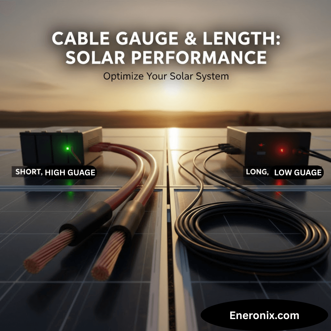
Two factors determine how much resistance a cable introduces: its length and its cross-sectional area. Remember that elementary physics class? Longer cables have more copper atoms in the current’s path, creating more resistance. Thinner cables force current through a smaller cross-section, concentrating resistance over less material. Both effects are linear and predictable, which means they’re also cumulative when you make poor choices on both dimensions.
In practice, this resistance causes two problems that directly impact solar system performance: voltage drop and heat generation. These aren’t separate issues, they’re two sides of the same physical process.
Voltage Drop
Voltage drop is the reduction in electrical potential that occurs as current travels through a resistive conductor. Think of it like pressure loss in a water pipe: the longer and narrower the pipe, the more pressure you lose between the pump and the destination. In electrical terms, that lost voltage represents energy that’s being converted to heat in the cable instead of being delivered to your battery or inverter.
The relationship is described by Ohm’s Law: V = I × R. Voltage drop equals current multiplied by resistance. This is why DC solar systems are particularly vulnerable, they often operate at low voltages with high currents, and current is the killer in this equation. A 48V system drawing 20A experiences the same voltage drop in a given cable as a 12V system drawing 20A, but that same absolute voltage loss represents a much larger percentage of the available voltage in the 12V system.
Here’s what that looks like in real numbers. If you lose 1 volt in a cable:
In a 12V system, you've lost 8.3% of your available voltage

In a 24V system, you've lost 4.2%

In a 48V system, you've lost 2.1%
This is why I push clients toward higher system voltages whenever it’s practical. It’s not about the technology being “better”, it’s about basic physics giving you more margin for error.
The Industry Standard: 2-3% Maximum Voltage Drop
The solar industry generally accepts 2-3% voltage drop as the maximum for DC circuits. This isn’t arbitrary. It’s based on the point where losses start meaningfully impacting charge efficiency and component operation. Some installers will tell you they target 1% or less, that’s even better, but it often requires cable sizing that’s cost-prohibitive for residential systems.
What I see fail most often are systems designed to exactly 3% voltage drop on paper, with no margin for real-world conditions. Cable resistance increases with temperature. Connections add resistance. Corrosion at terminals adds resistance. If you design to exactly 3% at 25°C with perfect crimps, you’re probably running at 4-5% in actual operation during summer afternoons. That’s where problems start.
Three percent doesn’t sound like much, but consider what it means across the life of a system. If your solar array generates 5 kWh per day and you’re losing 3% to cable resistance, that’s 150 Wh daily. Over a year, that’s 54.75 kWh you paid for but never used, energy that was converted to heat in your cables instead of charging your batteries. Over ten years, that’s 547.5 kWh of wasted generation. At $0.12/kWh, that’s $65 worth of electricity lost to resistance, and that’s assuming only 3% loss and ignoring the compounding effects on battery life.
Why Low-Voltage Systems Get Hit Harder
This is where a lot of people’s intuition fails them. The assumption is that higher voltage means higher losses because voltage is “more powerful.” The physics says the opposite.
Power (watts) equals voltage multiplied by current: P = V × I. For a given power requirement, if you halve the voltage, you must double the current to deliver the same watts. And because voltage drop is determined by current (V = I × R), doubling the current doubles the voltage drop in the same cable.
I’ll make this concrete with a real scenario I see constantly. You have a 1000W inverter load:
12V system: 1000W ÷ 12V = 83.3A
48V system: 1000W ÷ 48V = 20.8A
If you run both through the same cable, say, 10 AWG over 10 feet, the 12V system is pushing four times the current through that conductor. The voltage drop will be four times higher. The heat generated in the cable will be sixteen times higher (heat = I²R, so quadrupling current means 16× the thermal losses).
This is why off-grid RV systems, marine installations, and small residential systems using 12V or 24V architectures are the most vulnerable to cable-sizing mistakes. The high currents magnify every resistance problem. A cable gauge that works fine at 48V becomes a serious bottleneck at 12V.
What looks good on paper, “I’ll just use heavier cables”, runs into practical limits. You can’t always fit 4/0 AWG cable into a battery terminal. You can’t always route 2-inch-diameter cables through existing conduit. And the cost differential becomes significant when you’re talking about 20-30 feet of run. This is why system voltage selection is the first decision that affects every cable choice downstream.
Heat: The Visible Symptom of an Invisible Problem
Voltage drop is the performance killer, but heat is the safety issue. When current flows through resistance, electrical energy converts to thermal energy. This is unavoidable, it’s the same principle that makes your electric heaters work. The difference is that in a heater, heat generation is the goal. In a cable, it’s waste.
Undersized cables operating at high current get warm. Then hot. In extreme cases, like a 12V inverter pulling 150A continuous through 10 AWG cable, they get hot enough to damage insulation, accelerate oxidation at connection points, and create fire risk.
I’ve pulled cables from systems where the insulation was brittle and cracked from chronic heat exposure. The gauge was technically within NEC ampacity ratings for that conductor type, but the installer hadn’t accounted for the fact that the cable was in an enclosed space with no airflow, running continuously at near-maximum rated current. The NEC tables assume certain installation conditions. Real installations often violate those assumptions.
Heat also creates a feedback loop: hotter cables have higher resistance, which creates more voltage drop, which forces the source to push more current to maintain power delivery, which generates more heat. In battery systems with poorly sized cables, I’ve seen this manifest as the charge controller or inverter progressively ramping up current to compensate for sagging voltage, which accelerates the heating problem until something trips on thermal protection or voltage limits.
The practical takeaway: if your cables feel more than slightly warm to the touch during normal operation, they’re undersized for the application. This is especially true for battery-to-inverter cables, which can carry surge currents far higher than the continuous rating. A cable that’s fine at 30A continuous might overheat during a 90A inverter surge, even if that surge only lasts a few seconds.
Why Solar Systems Are Particularly Sensitive
Grid-connected AC systems distribute power at 120V or 240V, which keeps currents relatively low for typical household loads. A 1500W load on a 120V circuit draws 12.5A. That same load on a 12V DC system draws 125A, ten times the current through the same power delivery.
Solar systems also have unique current profiles. MPPT charge controllers can pull maximum current from the array during peak sun, then taper to nearly zero during cloudy conditions. Inverters can surge to 2-3× their continuous rating during motor starts or other inrush loads. Batteries supply whatever current the load demands, subject only to their internal resistance and the BMS limits, which means an undersized cable becomes the chokepoint that everything else in the system has to work around.
The other factor: solar systems often involve longer cable runs than typical residential wiring. Panels are on the roof. Batteries are in the garage or basement. The inverter might be near the main panel, which is nowhere near the batteries. I’ve seen systems where the DC cable runs total 60-80 feet round-trip just because of building layout constraints. Every foot adds resistance.
In grid-tie residential wiring, you’re typically running 15-20 feet from the breaker panel to an outlet. In solar systems, you might be running 25 feet from panels to charge controller, another 15 feet from charge controller to batteries, and 20 feet from batteries to inverter. Those 60 feet of total DC cabling, if undersized, can easily consume 5-7% of your generated power as heat.
This is why solar installers who come from a residential electrician background sometimes underestimate cable sizing requirements. The rules they know for 120V branch circuits don’t translate directly to 12V or 24V DC solar circuits. The currents are an order of magnitude higher. The acceptable voltage drop percentages are tighter. And the consequences of getting it wrong compound over time instead of just tripping a breaker.
How Cable Problems Kill Performance
Voltage Drop in Action
When I’m troubleshooting a system that “isn’t charging right,” the first thing I do is measure voltage at multiple points under load. I’ll check voltage at the charge controller output terminals, then again at the battery terminals, while the controller is actively charging. The difference between those two readings is your cable drop.
In a properly sized system, that difference should be negligible, maybe 0.1-0.2V under normal charging current. In undersized systems, I regularly see 0.5-1.5V difference. That might not sound like much, but consider what it means: if your charge controller is outputting 14.4V to charge a 12V battery, but only 13.2V is actually reaching the battery terminals because you’re losing 1.2V in the cables, your battery never sees the voltage it needs to fully charge.
The charge controller doesn’t know this is happening. It’s measuring voltage at its own terminals and doing exactly what it’s programmed to do. The battery BMS doesn’t know either, it just sees that it’s never quite reaching the absorption voltage threshold. The system appears to be working, but it’s chronically underperforming in a way that won’t show up in monitoring data unless you’re specifically looking for it.
This is the insidious nature of voltage drop: everything looks functional. The charge controller shows green lights. The battery accepts charge. But month after month, the battery never cycles through a proper full charge sequence, which means it’s slowly drifting out of balance and losing calibration. After 12-18 months, you’ve got a battery bank that reports 85% health but only delivers 70% of rated capacity because it’s been operating in a partially charged state the entire time.
The Cascading Effects Through Your System
Voltage drop doesn’t just affect one component, it propagates through the entire energy chain, degrading performance at every stage.
Solar Panels and MPPT Controllers
MPPT charge controllers work by finding the maximum power point of the solar array and converting that to the appropriate voltage and current for battery charging. This involves running the array at whatever voltage produces maximum power (typically 17-22V for a “12V” panel) and then buck-converting that down to battery charging voltage while increasing current.
But if the cables between the MPPT output and the battery have significant voltage drop, the MPPT sees a lower voltage at its output than it expects. This affects its algorithm. The controller thinks the battery voltage is lower than it actually is (because it’s measuring at the controller terminals, not the battery terminals), so it may push more current to compensate. This isn’t necessarily wrong, it’s doing what it’s designed to do, but it means the array isn’t operating at its true maximum power point. You’re getting slightly less power conversion efficiency than you would with properly sized cables.
In extreme cases, the MPPT might oscillate, hunting for a stable operating point that doesn’t actually exist because the voltage it’s measuring keeps changing as current fluctuates. I’ve seen this manifest as the charge current ramping up and down in a slow cycle, never stabilizing, because the control loop is fighting cable resistance.
The other issue: many MPPTs have a minimum battery voltage threshold below which they won’t operate. If cable drop is severe enough that battery voltage at the controller terminals falls below this threshold during high-current charging, the MPPT will shut down or go into fault mode. I’ve diagnosed systems where the MPPT would start charging in the morning, ramp up to high current by mid-morning, then fault out on “low battery voltage” even though the battery itself was fine, it was just that the cables were dropping enough voltage under load to trigger the protection threshold.
Batteries: The Hidden Capacity Loss
Batteries are remarkably tolerant of abuse, which is both their strength and their weakness. They’ll accept whatever charge you give them and deliver whatever current you ask for, degrading quietly in the background without throwing errors or warning lights.
Chronic undercharging from cable-induced voltage drop manifests in several ways. Lithium batteries, particularly LiFePO4, rely on reaching a specific absorption voltage (constant-voltage) phase, to trigger the final stage of the charge cycle where the BMS balances cells and recalibrates state-of-charge estimation. If you never quite reach that voltage because cables are dropping 0.8V under load, the BMS never completes its balancing routine. Over hundreds of cycles, cells drift apart in voltage. The pack’s usable capacity decreases because the weakest cell hits its upper voltage limit before the rest of the pack is full.
Lead-acid batteries have a different failure mode but the same outcome. They need to reach 14.4-14.8V (for a 12V bank) to fully charge and desulfate the plates. If cable drop means they only see 13.8V at the terminals, they’ll accept some charge and appear to work, but they never fully charge. Sulfation accumulates. Capacity degrades. After a year of this, a 200Ah battery bank might only deliver 140Ah, and the owner has no idea why because “the system charges every day.”
I test this by measuring battery terminal voltage during charging with the cables connected, then measuring again with the cables temporarily disconnected and the battery charged from a bench supply. The difference in the voltage required to reach “full” tells me how much the cables were stealing from the charge process. It’s often eye-opening for system owners who thought their batteries were just “getting old.”
Inverters: Operating on the Edge
Inverters are designed with low-voltage cutoff protection to prevent over-discharging the battery. For a 12V system, this is typically 10.5-11.5V depending on configuration. The problem is that this threshold is measured at the inverter’s input terminals, not at the battery itself.
If you have 1V of cable drop between the battery and inverter (which is common in undersized installations), the inverter “sees” a voltage 1V lower than what the battery is actually at. This means the inverter will hit its low-voltage cutoff and shut down when the battery is still at 11.5-12.5V, well above the point where it should actually stop discharging.
This looks like the battery being undersized or failing, when actually it’s cable drop forcing the inverter to shut down prematurely. I’ve had clients report that their batteries “only last two hours” when the actual battery capacity is fine, the inverter is just cutting off early because it’s seeing artificially low voltage through resistive cables.
The other failure mode: inverters compensate for low input voltage by drawing more current to maintain output power. If the battery voltage at the inverter terminals is sagging due to cable drop, the inverter pulls more amps to deliver the same watts at the output. This increases current through those already-undersized cables, which increases voltage drop further, which forces the inverter to pull even more current. This feedback loop can push cables into thermal overload or trip the inverter's overcurrent protection, even though the actual load on the AC side is within the inverter's rating.
I’ve seen 3000W inverters trip on DC overcurrent while powering a 2000W load, simply because the cables between the battery and inverter were 10 AWG over 15 feet instead of the 2/0 AWG they should have been. The inverter was trying to pull 200+ amps to compensate for the voltage sag, when it should have been pulling 160A with proper cables.
The System-Wide Performance Tax
The cumulative effect of these component-level impacts is a system that perpetually underperforms against its rated capacity. You paid for a 3kW solar array, but you’re effectively getting 2.7kW delivered to the battery because 300W is being lost as heat in the cables. You bought a 10kWh battery bank, but you only get 7.5kWh of usable energy because cable drop causes the inverter to shut down before the battery is actually depleted.
This is the part that frustrates me when I audit systems that are “not working as expected.” On paper, everything is correctly sized. The solar array should be producing enough energy. The battery should last through the night. But nobody calculated the cumulative voltage drop across all the DC cable runs in the system, so 15-20% of the energy generated never makes it to where it needs to go.
And because this degradation happens gradually, a little bit every day, compounding over months, it’s rarely noticed until something fails outright. The battery that should have lasted 10 years fails at year 5. The inverter that should handle the load fine keeps tripping. The system that should be self-sufficient during power outages runs out of juice after six hours instead of twelve.
Heat: The Physical Evidence of Waste
Electrical resistance converts current into heat via I²R losses. This is basic physics, but the squared relationship means heat generation increases dramatically with current. Double the current, and you quadruple the heat. This is why low-voltage systems with high currents are particularly vulnerable.
I’ve measured cable surface temperatures of 50-60°C (122-140°F) in undersized installations under full load. That’s hot enough to degrade PVC insulation over time, especially if the cables are in an enclosed space or bundled together with no airflow. The NEC ampacity tables account for this to some degree, but they assume certain installation conditions, open air, specific ambient temperatures, limited conduit fill. Real installations often violate these assumptions.
Heat also accelerates corrosion at connection points. Copper oxidizes faster at elevated temperatures. That thin layer of copper oxide at a lug connection adds resistance, which generates more heat, which accelerates oxidation further. I’ve seen battery terminals where the copper turned black and the connection resistance increased to the point where the terminal itself became the primary voltage drop in the circuit, not the cable, but the connection point that was chronically overheating.
The feedback loop I mentioned earlier, heat increasing resistance, which increases voltage drop, which forces higher current, which generates more heat, can escalate to thermal runaway in extreme cases. This is rare in properly protected systems (breakers or fuses should trip first), but I’ve investigated installations where cables were warm enough to melt the insulation on adjacent wires or scorch the wall behind them.
The practical warning sign: if any cable in your DC system is noticeably warm to the touch during normal operation, it's too small for the current it's carrying. "Warm" doesn't necessarily mean "dangerous," but it does mean you're wasting power as heat and degrading the cable faster than it should. Cables should operate at or near ambient temperature under normal load. If they don't, you have a sizing problem.
Heat, Safety, and Fire Risk
Most electrical fires don’t start with dramatic sparks or immediate combustion. They start with chronic overheating that gradually degrades insulation, dries out nearby materials, and creates a hot spot that eventually finds something flammable.
Undersized cables running at high current create exactly this condition. The cable gets warm. Over weeks and months, the insulation becomes brittle. A slight movement or vibration cracks the insulation. The conductor makes intermittent contact with something it shouldn’t, a grounded surface, another conductor, a metal junction box. Now you have arcing at that point, which generates much more heat than resistive losses alone.
I’ve seen this progression in RV installations more than anywhere else, because RVs combine high currents (12V systems with large inverters), tight spaces (cables bundled together in enclosed compartments), and vibration (everything shakes when driving). A cable that was marginal when installed becomes a hazard after two years of road use.
The other fire risk is at connection points. Undersized cables force high currents through terminals and lugs that may not be rated for that sustained load. Even if the cable itself doesn’t overheat, the terminal can. I’ve pulled battery terminals that were partially melted from heat, with the insulation drawn back several inches from the lug because it had been chronically above its temperature rating.
This is why proper cable sizing isn’t just about performance, it’s about safety and longevity. An undersized cable might work for months or even years before it fails catastrophically, but the failure mode is often destructive. It’s not like a breaker tripping cleanly. It’s insulation melting, connections arcing, or thermal damage to adjacent components.
The Economic Reality: Paying for Power You Never Use
Here’s the calculation that should make every installer and system owner care about cable sizing: every watt lost to resistance is a watt you paid for but didn’t get.
If your system generates 5kW at peak production but loses 5% to cable resistance, you’re wasting 250W. Over a 5-hour peak sun day, that’s 1.25kWh daily. Over a year, that’s 456kWh. If you’re off-grid, that’s 456kWh that could have charged your batteries or run your loads, but instead it heated your cables. If you’re grid-tied and that energy would have been sold back at $0.10/kWh, you lost $45.60 annually.
That doesn’t sound like much until you multiply it over the 25-year life of the system. That’s $1,140 in wasted generation. And if that 5% loss was avoidable by spending an extra $200 on proper cable sizing at installation, you’ve lost $940 over the system’s life, not counting the accelerated wear on batteries and other components from chronic undervoltage operation.
The more insidious cost is the compensatory oversizing. If your cables are losing 5% of generation, you might “solve” this by adding more panels to make up the difference. But you’re paying $3,000 for an extra kilowatt of solar capacity to compensate for a cable problem that could have been fixed for $300. I see this constantly: systems with oversized arrays relative to the battery bank, not because the owner needs that much generation, but because the installer unconsciously compensated for cable losses by adding more panels instead of fixing the root cause.
The same thing happens with batteries. If your cables are causing the inverter to shut down prematurely on low voltage, the battery appears undersized. So you add another battery module. That’s $1,500-$2,500 to fix a problem that was actually caused by $50 worth of undersized cable between the battery and inverter.
This is why I tell clients: cable sizing is the cheapest performance optimization in a solar system. It’s a one-time decision at installation, the cost difference between correct and incorrect sizing is usually a few hundred dollars, and the performance impact extends across the entire life of the system. Every other component, panels, batteries, charge controllers, inverters, will be replaced or upgraded over 25 years. Cables, if installed correctly, will outlast all of it. If installed incorrectly, they’ll degrade everything else in the system until you finally rip them out and do it right.
For Homeowners: What You Need to Know
Whether you’re evaluating quotes from installers or trying to understand why your existing system isn’t performing as expected, cable sizing is one of the few technical details where you can, and should, ask pointed questions. You don’t need to become an electrical engineer, but you do need to know what separates a professional installation from one that’s going to cause problems.
Questions to Ask Your Installer
When I’m reviewing proposals for clients, I look for specificity in the cable specifications. Vague language like “standard solar wiring” or “appropriate gauge cables” tells me the installer either hasn’t done the calculation or doesn’t want to commit to numbers they might have to defend later.
What cable gauge are you specifying for each DC circuit, and why?
A competent installer should be able to tell you, without hesitation: “We’re using 6 AWG from the array to the charge controller because the run is 28 feet and the maximum current is 35A. We’re using 2/0 AWG from the battery to the inverter because it’s a 15-foot run and the inverter can draw up to 250A on surge.”
If they can’t give you specific gauge numbers and the reasoning behind them, that’s a warning sign. It suggests they’re using a one-size-fits-all approach based on what they have in the truck, not what your system actually requires.
Can you show me the voltage drop calculation?
This is where you separate professionals from parts-changers. A real installer will have calculated voltage drop for every DC circuit in the system. They should be able to show you the numbers: cable length, current, gauge, and the resulting voltage drop percentage.
If they look confused by this question, or tell you “we always use [X gauge] and it’s never been a problem,” you’re dealing with someone who’s installing by habit, not by design. That works until it doesn’t, and you’re the one who pays for it when the system underperforms.
In practice, I’ve seen plenty of installers who can wire a system correctly from experience without formally calculating anything. But they should still be able to produce the calculation when asked, even if they have to do it on the spot. The calculation itself is straightforward, the fact that they’re willing to do it tells you they understand why it matters.
What's the total DC cable run length for each circuit?
This question catches oversights. The installer should know exactly how far it is from panels to charge controller, charge controller to battery, and battery to inverter. If they’re estimating or hand-waving, they haven’t thought carefully about equipment placement and cable routing.
What I see fail most often: installers who measure the straight-line distance between components, then multiply by 1.5 or 2 to account for routing, and call it good. That might work, but it also might not if the actual installed route ends up longer because of obstacles, code requirements, or building structure constraints. A professional will have walked the route and measured it, or at minimum added generous margin to their estimate.
Are you following NEC voltage drop guidelines?
The National Electrical Code doesn’t mandate a specific voltage drop limit for most circuits, but it recommends 3% maximum for branch circuits and 5% total for the combination of feeder and branch circuits. For solar DC circuits, 2-3% is industry standard.
An installer who’s familiar with NEC guidelines will immediately know what you’re asking about. Someone who isn’t might stumble or deflect. This tells you whether they’re approaching the installation as an electrical system subject to code and best practices, or as a collection of solar components they’re hooking together.
Red Flags in Quotes and Proposals
I audit a lot of solar proposals for clients who want a second opinion before signing. Here’s what makes me concerned:
Missing cable specifications entirely.
If the proposal lists panel model, inverter model, battery model, but doesn’t mention cable gauge or type anywhere, the installer hasn’t thought about it yet. They’ll figure it out when they show up to install, which means they’ll use whatever they have or whatever’s cheapest at the supply house that day.
Very long cable runs that could be avoided.
Sometimes long runs are unavoidable due to building layout or code requirements. But if I see a system with 40 feet of cable between the battery and inverter when those components could easily be 10 feet apart with different placement, it tells me the installer optimized for their convenience, not for system performance. Every unnecessary foot of cable costs you voltage drop.
Thin cables on high-current circuits.
This is most common in 12V systems where installers underestimate the current requirements. I’ve seen proposals specifying 10 AWG for a battery-to-inverter run that’s going to carry 150A on surge. That cable will work in the sense that it won’t immediately melt, but it’s going to drop 2-3V under load, which will cause all the problems I described in Section III.
We always use [X gauge] for everything.
This tells me the installer has a standard approach they apply to every system regardless of specifics. That might be fine if their standard is conservative (always oversizing cables), but it’s more often a sign that they haven’t customized the design to your system’s actual requirements. Cable sizing depends on current and distance, both of which vary from one installation to the next.
Voltage drop calculations that are missing or obviously wrong.
Some installers will include voltage drop calculations in the proposal to look professional, but the numbers don’t make sense when you check them. I’ve seen calculations that used one-way distance instead of round-trip, or that used the wrong resistance values for the cable gauge, or that calculated percentage drop based on nominal system voltage instead of actual operating voltage. If the calculation shows 1.2% voltage drop for a circuit that I know should be more like 4%, something’s wrong with their math, and that means something’s wrong with their cable selection.
What Good Looks Like
A professional proposal will include:
- Specific cable gauge for each DC circuit (array to charge controller, charge controller to battery, battery to inverter)
- Cable type specifications (THHN, USE-2, PV wire, etc.) appropriate for the installation environment
- Actual or maximum cable run lengths for each circuit
- Voltage drop calculations showing percentage drop for each circuit under maximum expected current
- Cable sizing that matches or exceeds manufacturer recommendations for the inverter, charge controller, and battery
The proposal should also show evidence of thoughtful equipment placement. If the charge controller is spec’d to be installed right next to the battery bank, that’s good, it minimizes cable runs. If the inverter is going to be installed 30 feet from the batteries for no clear reason, that’s questionable.
Beyond the proposal itself, a good installer will be willing to discuss these details with you. If you ask about cable sizing and they seem annoyed or dismissive, “trust me, I’ve done hundreds of these”, that’s a bad sign. A confident professional will welcome technical questions because it shows the client cares about quality.
Cost-Benefit: When to Push Back on Cheap Cables
Cable is one of the few areas where the cost difference between adequate and optimal is relatively small, but the performance difference is significant.
If an installer is proposing 8 AWG for a circuit where 6 AWG would be better, the cost difference might be $3-4 per foot. For a 30-foot run, that’s $90-120. If that $100 investment eliminates 1% of voltage drop in a circuit that carries 30A at 48V, you’re saving roughly 14W of continuous loss, which over 25 years is 3,066 kWh. At $0.12/kWh, that’s $368 worth of electricity over the system’s life. The cable pays for itself many times over.
This is why I tell homeowners: don’t let installers cheap out on cables to save a few hundred dollars on the total system cost. If the quote comes in at $18,500 and you ask them to upgrade to the next larger gauge on all DC circuits and it goes to $18,800, pay the extra $300. It’s the best $300 you’ll spend on the system.
The place where this gets contentious is when upgrading cables requires other changes, like larger conduit, different terminal lugs, or modified equipment mounting to accommodate bulkier wire. That can add labor cost beyond just the cable itself. In those cases, the cost-benefit calculation is more nuanced, but the principle remains: undersized cables will cost you more over the system’s life than proper cables cost upfront.
Evaluating Your Existing System
If you already have a solar system installed and you’re seeing performance issues, cable sizing might be the culprit. Here’s how to check:
Batteries that never fully charge.
If your monitoring shows the battery bank consistently stopping at 85-90% state of charge even on sunny days with no loads running, measure voltage at the charge controller output terminals and at the battery terminals while charging. If there’s more than 0.2-0.3V difference, your cables are too small or the connections have too much resistance.
Inverter shutting down unexpectedly.
If the inverter cuts out on low voltage while the battery monitoring shows the battery still has 30-40% charge remaining, you likely have excessive voltage drop between the battery and inverter. The inverter sees a lower voltage than the battery actually has, so it shuts down prematurely.
Warm or hot cables during operation.
Touch the DC cables during peak production or while the inverter is running a moderate load. They should be at or near ambient temperature. If any cable is noticeably warm, it’s carrying more current than it should for that gauge. This is both a performance problem (wasted energy as heat) and a potential safety issue.
System performance degrading over time.
If the system worked fine for the first six months and has been gradually declining since, check all cable connections for corrosion or loosening. Heat from undersized cables accelerates corrosion at terminals, which increases resistance, which makes the problem worse. I’ve seen systems where cleaning and re-tightening all the connections temporarily fixed performance issues, only to have them return a few months later because the underlying cable sizing problem was still causing chronic overheating.
When to Call for Professional Assessment
If you suspect cable sizing issues but aren’t comfortable making measurements yourself, a qualified solar technician can assess the system in an hour or two. What they should do:
- Measure voltage drop across each DC circuit under load
- Check cable temperature during operation
- Verify that installed cable gauges match the system’s current requirements
- Inspect all terminals and connections for signs of overheating or corrosion
If the assessment confirms undersized cables, the fix might be as simple as replacing one critical cable run, often the battery-to-inverter connection, which typically carries the highest current and is most sensitive to voltage drop. That’s usually a few hundred dollars in parts and labor, which is vastly cheaper than replacing batteries or inverters that were degraded by chronic undervoltage operation.
What I see more often than I’d like: homeowners who live with poor performance for years, assuming “that’s just how it is” or “maybe the batteries are getting old,” when the actual problem is $400 worth of cable between the battery and inverter that was undersized from day one. A proper assessment would have identified this immediately, but nobody thought to check because the system appeared to be working.
What Should Be in Your Contract
Before any work starts, your installation contract should specify:
- Cable gauge for each DC circuit
- Cable type (insulation rating, conductor type)
- Maximum voltage drop under rated load
- Warranty coverage for cable-related performance issues
The last point is important. If the installer warrants the system will produce a certain amount of power or the batteries will charge to a specific percentage, but they used undersized cables that prevent the system from meeting those targets, you have recourse. But only if the performance expectations were in the contract.
In practice, most residential solar contracts are vague on these details, which makes it hard to hold installers accountable for cable-related problems after the fact. This is why asking detailed questions up front and getting specific answers in writing matters. If the installer commits to “less than 2% voltage drop on all DC circuits” in the contract, and you later measure 4% drop, that’s a defect they’re obligated to fix.
For DIY Installers: How to Size Your Cables
If you’re building your own system, cable sizing is one of the few decisions where precision matters more than brand names or premium components. You can get away with mid-range panels or a budget charge controller if you size them correctly, but no amount of expensive equipment will compensate for cables that can’t deliver the power those components are trying to move.
The Planning Phase: Map Before You Buy
The single biggest mistake I see in DIY installations is buying cables based on what “should” work, then discovering during installation that the actual routing requires longer runs than expected. By that point, you’ve already committed to a cable gauge that’s now marginal for the actual installed length.
Start by physically mapping where every component will be installed. Not approximate locations, actual positions. Mark where the panels will mount, where the charge controller will go, where the battery bank will sit, and where the inverter will be installed. Then trace the actual cable routes between these points, accounting for:
- Obstacles (you can’t run cable through structural members)
- Code requirements (minimum distances from gas lines, required conduit, etc.)
- Accessibility (cable runs need to be serviceable)
- Thermal environment (cables in hot attics need derating)
Measure these routes and add 10-15% margin. This is your actual cable length for calculations. I’ve seen systems where the straight-line distance from panels to charge controller was 12 feet, but the actual installed cable run was 22 feet because it had to route around a roof penetration, down through a wall cavity, and across a ceiling space.
Gathering Your Numbers
You need three pieces of information for each cable run:
1. System voltage:
This is straightforward, 12V, 24V, or 48V nominal. But remember that actual operating voltage varies. A “12V” system operates at 10.5V when the battery is depleted and 14.6V when charging. For voltage drop calculations, use the lowest voltage the system will operate at, because that’s when voltage drop has the most impact.
2. Maximum current:
This is where DIY installers often get tripped up. You need to know the maximum current that will flow through each cable, not the average or typical current.
For the panel-to-charge-controller run: use the array short-circuit current (Isc) from the panel specifications, multiplied by the number of parallel strings, then multiplied by 1.25 per NEC requirements. If you have four panels in parallel, each rated at 10A Isc, your maximum current is 4 × 10A × 1.25 = 50A.
For the charge controller-to-battery run: use the charge controller’s maximum output current rating. A 60A charge controller means you need to size cables for at least 60A, preferably more if you’re planning to add panels in the future.
For the battery-to-inverter run: use the inverter’s maximum DC input current, which is usually specified in the manual. If it’s not, calculate it from the inverter’s maximum AC output power divided by the minimum battery voltage. A 3000W inverter on a 12V system could draw up to 3000W ÷ 10.5V = 286A during surge. That’s the current your cables need to handle.
3. Cable run length:
Use your measured and margined number from the planning phase. And remember: voltage drop calculations use the total conductor length, which is twice the one-way distance. If the battery is 10 feet from the inverter, the current flows 10 feet through the positive cable and 10 feet back through the negative cable, 20 feet total. Some calculators ask for one-way distance and double it internally, others ask for total length. Know which type you’re using.
Option 1: Use an Online Calculator
This is the approach I recommend for most DIY installers because it’s fast, accurate, and eliminates math errors. There are several good calculators available:
- Blue Sea Systems voltage drop calculator
- Cerrowire voltage drop calculator
- Engineering ToolBox wire gauge calculator
These tools work similarly: you input system voltage, current, cable length (check whether it wants one-way or round-trip), and target voltage drop percentage. The calculator tells you the minimum wire gauge needed.
Here's a worked example using typical numbers:

System voltage: 12V

Maximum current: 150A (inverter DC input)

One-way cable length: 8 feet (16 feet round-trip)

Target voltage drop: 2%
Plugging these into a calculator gives you a minimum wire size of 1/0 AWG. If you want to get down to 1% drop for better efficiency, you’d need 3/0 AWG.
The calculator does all the work, resistance per foot for different wire gauges, the voltage drop formula, the percentage calculation. Your job is just to input accurate numbers and interpret the result.
Option 2: Calculate It Manually
If you want to understand what’s actually happening or you need to verify a calculator result, here’s the formula:
VD = (2 × L × R × I) ÷ 1000
Where:
- VD = voltage drop in volts
- L = one-way cable length in feet
- R = resistance per 1000 feet for your chosen wire gauge (from NEC tables)
- I = current in amperes
The factor of 2 accounts for both conductors (positive and negative). The division by 1000 converts the resistance value (which is specified per 1000 feet) to the actual cable length.
Once you have VD in volts, convert to percentage:
Voltage Drop % = (VD ÷ System Voltage) × 100
Let’s work through the same example manually:
- L = 8 feet
- I = 150A
- System voltage = 12V
- We’ll try 1/0 AWG, which has a resistance of 0.1 ohms per 1000 feet for copper
VD = (2 × 8 × 0.1 × 150) ÷ 1000 = 240 ÷ 1000 = 0.24V
VD% = (0.24 ÷ 12) × 100 = 2%
That confirms the calculator result, 1/0 AWG gives us exactly 2% drop.
If we try 2/0 AWG (resistance 0.0795 ohms per 1000 feet):
VD = (2 × 8 × 0.0795 × 150) ÷ 1000 = 190.8 ÷ 1000 = 0.191V
VD% = (0.191 ÷ 12) × 100 = 1.6%
And 3/0 AWG (resistance 0.063 ohms per 1000 feet):
VD = (2 × 8 × 0.063 × 150) ÷ 1000 = 151.2 ÷ 1000 = 0.151V
VD% = (0.151 ÷ 12) × 100 = 1.26%
So the progression is: 1/0 AWG = 2%, 2/0 AWG = 1.6%, 3/0 AWG = 1.26%. Each step up in size reduces voltage drop, but the cost and physical bulk increase as well.
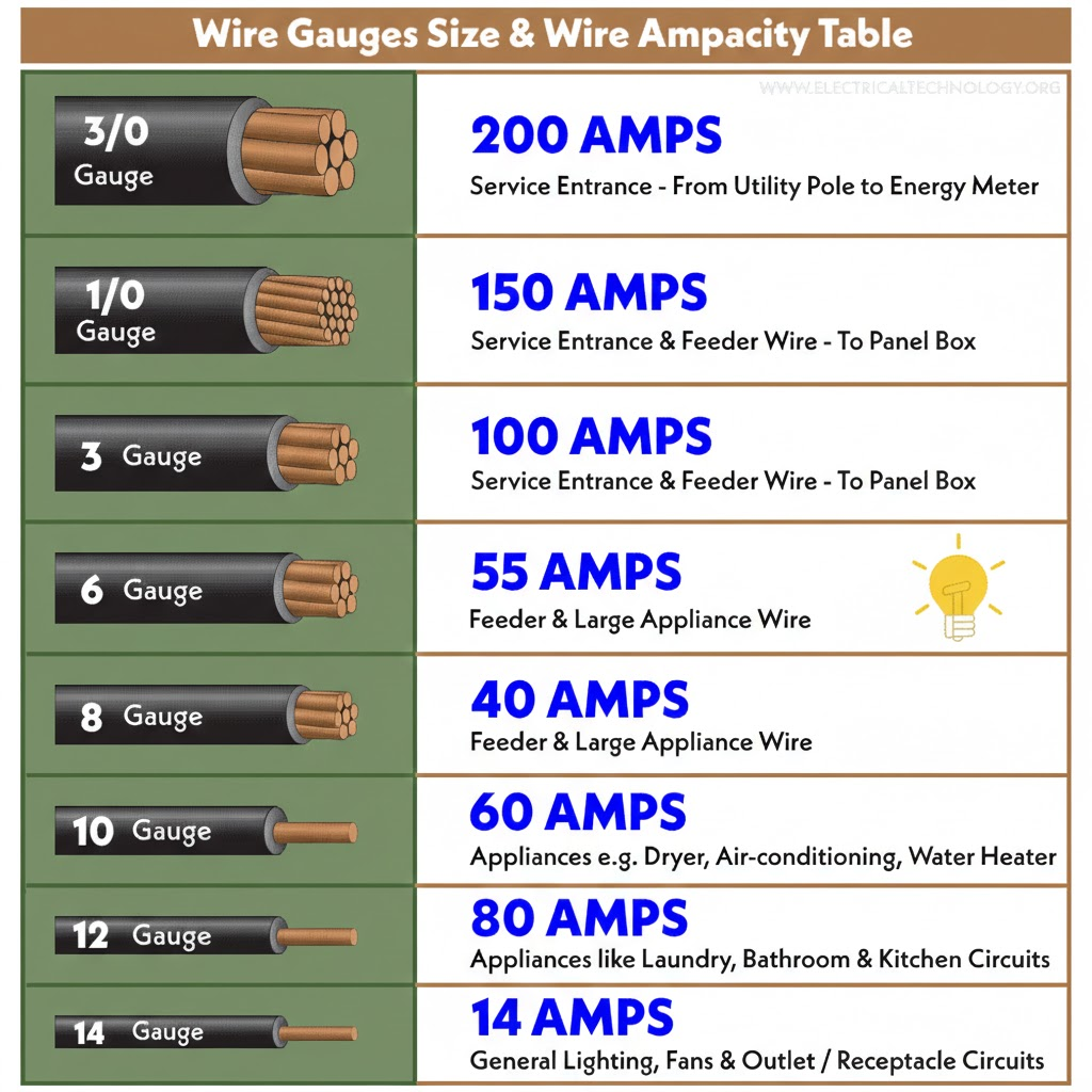
Quick Reference Tables
For common scenarios, here are wire gauge recommendations to keep voltage drop under 3%:
12V Systems:
- 10A / 10ft → 14 AWG
- 10A / 20ft → 12 AWG
- 20A / 10ft → 10 AWG
- 20A / 20ft → 8 AWG
- 50A / 10ft → 4 AWG
- 50A / 20ft → 1 AWG
- 100A / 10ft → 2/0 AWG
- 100A / 20ft → 4/0 AWG
24V Systems:
- 10A / 10ft → 16 AWG
- 10A / 20ft → 14 AWG
- 20A / 10ft → 12 AWG
- 20A / 20ft → 10 AWG
- 50A / 10ft → 6 AWG
- 50A / 20ft → 2 AWG
- 100A / 10ft → 1/0 AWG
- 100A / 20ft → 3/0 AWG
48V Systems:
- 10A / 10ft → 18 AWG
- 10A / 20ft → 16 AWG
- 20A / 10ft → 14 AWG
- 20A / 20ft → 12 AWG
- 50A / 10ft → 8 AWG
- 50A / 20ft → 4 AWG
- 100A / 10ft → 2 AWG
- 100A / 20ft → 1/0 AWG
These tables assume copper conductors at 75°C insulation rating (THHN/THWN) in normal ambient temperature. If your installation involves high temperatures or conduit fill, you may need to upsize further.
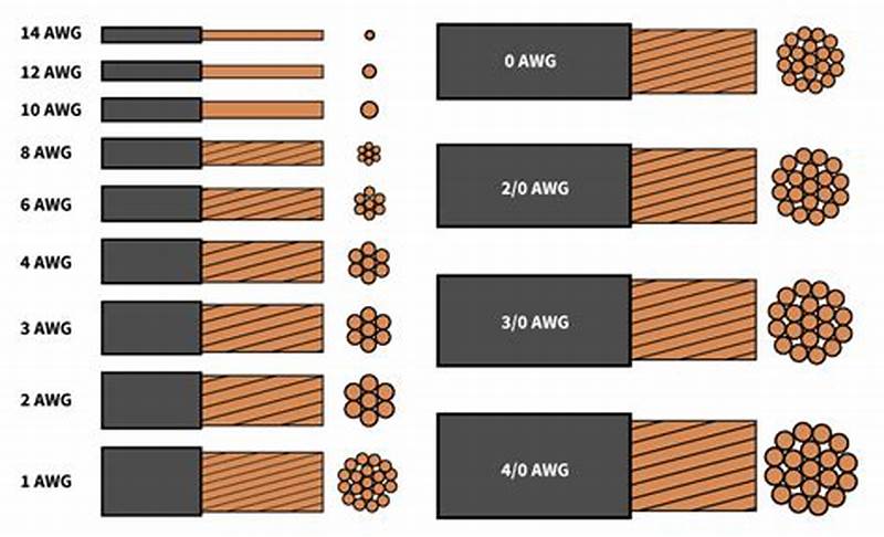
Understanding Wire Gauge: AWG and mm²

American Wire Gauge (AWG) is standard in North America, but international markets use cross-sectional area in square millimeters (mm²). The relationship isn’t intuitive, smaller AWG numbers mean larger wire, and the progression isn’t linear.
Common conversions:
- 10 AWG ≈ 6 mm²
- 8 AWG ≈ 10 mm²
- 6 AWG ≈ 16 mm²
- 4 AWG ≈ 25 mm²
- 2 AWG ≈ 35 mm²
- 1 AWG ≈ 50 mm²
- 1/0 AWG ≈ 55 mm²
- 2/0 AWG ≈ 70 mm²
- 3/0 AWG ≈ 95 mm²
- 4/0 AWG ≈ 120 mm²
If you’re buying cable online or importing components, verify whether the listing uses AWG or mm². I’ve seen DIY builders order “10mm² cable” thinking it was equivalent to 10 AWG, when actually 10mm² is roughly 8 AWG, two sizes smaller.
Stranded vs. Solid Cable: When to Use Each

Stranded cable consists of many small conductors twisted together. Solid cable is a single conductor. For the same AWG rating, they have similar resistance, but different applications:
Use stranded cable for:
1. Any cable that will flex or vibrate (battery connections, inverter input cables)

2. Connections to equipment with screw terminals designed for stranded wire

3. Runs through tight bends or complex routing

4. Anywhere flexibility matters
Use solid cable for:
1. Fixed, permanent runs through conduit

2. Long straight runs where the cable won't move after installation

3. Situations where slightly lower cost matters and flex isn't required
In practice, most DIY solar installations should use stranded cable for everything except possibly the panel-to-charge-controller run if it’s a long, straight conduit pull. The flexibility is worth the slight cost premium, and it makes terminations more reliable because stranded wire compresses better under terminal screws.
Copper Only: Why You Should Avoid Aluminum
Aluminum cable is cheaper and lighter than copper for the same current-carrying capacity, which is why the utility industry uses it for long transmission runs. But for DIY solar systems, aluminum creates more problems than it solves.
Aluminum has roughly 60% higher resistance than copper for the same cross-sectional area, so you need to upsize to compensate. It’s also more prone to corrosion at connection points, especially in the presence of dissimilar metals (like brass or copper terminals). The oxide layer that forms on aluminum is electrically insulating, unlike copper oxide which remains somewhat conductive. This means aluminum connections can develop high resistance over time even if they’re mechanically tight.
Aluminum also has different thermal expansion characteristics than copper, which can cause connections to loosen during thermal cycling. I’ve seen aluminum battery cables that were properly torqued at installation but had to be re-tightened every six months because the connection would gradually work loose as the cable heated and cooled.
The cost savings aren’t worth the reliability problems for a DIY system. Use copper, accept the higher cost, and don’t worry about it for the next 25 years.
Insulation Type: Matching Cable to Environment
The insulation type determines where you can legally and safely install the cable. Common types:
THHN/THWN: Standard building wire, rated for 90°C dry/75°C wet. Good for conduit runs in normal environments. Not suitable for direct burial or outdoor exposure to UV.
USE-2 or RHW-2: Rated for wet locations and direct burial. This is what you want for any cable that might be exposed to moisture or that runs underground.
PV Wire: Specifically designed for solar installations, rated for 90°C and UV-resistant. This is the correct choice for exposed outdoor runs from panels to the combiner box or charge controller. It’s more expensive than THHN, but it’s designed for exactly this application.
What I see go wrong: DIY installers using standard THHN for outdoor panel connections because it’s cheaper and readily available. THHN insulation will degrade under UV exposure in 2-4 years, leaving brittle insulation that cracks and exposes conductors. That’s a code violation and a safety hazard. Use the right cable for the environment, even if it costs more.
Common DIY Mistakes to Avoid
1. Using automotive wire for DC solar circuits.
Automotive wire is sized for short runs at 12V in a vehicle environment. It’s often under-insulated for building wiring and not rated for continuous duty at the currents solar systems demand. Use proper THHN, USE-2, or PV wire.
2. Measuring only one-way distance.
Current travels out through the positive cable and back through the negative cable. If you calculate voltage drop for 10 feet when the actual round-trip is 20 feet, you’ll be off by a factor of two.
3. Forgetting about temperature rise in conduit.
If you’re running multiple cables through conduit in a hot environment (like an attic in summer), the cables can’t dissipate heat as effectively as they would in open air. NEC requires derating for conduit fill and temperature. This can reduce the effective ampacity by 20-40%, which means you might need to upsize to compensate.
4. Mixing wire gauges in series.
If you have 10 feet of 4 AWG and 10 feet of 6 AWG in series on the same circuit, the total resistance is the sum of both segments. The thinner section creates a voltage drop bottleneck that negates some of the benefit of the heavier section. It’s better to use a consistent gauge for the entire run.
5. Undersized lugs or terminals.
The cable is only as good as its weakest connection. If you use 2/0 AWG cable but terminate it with a lug rated for 50A instead of 200A, that lug becomes the resistance bottleneck. Match lug ratings to the cable and expected current.
6. Skipping heat-shrink on crimped connections.
Crimped lugs should always be protected with adhesive-lined heat-shrink tubing. This seals out moisture, prevents corrosion, and provides strain relief. I’ve seen DIY crimps that looked fine at installation but were corroded to the point of failure within two years because they weren’t properly sealed.
Installation Best Practices
Crimping technique matters.
If you’re doing your own crimping, use a proper hydraulic crimper for anything larger than 10 AWG. Hammer-style crimpers don’t apply even pressure and can create weak connections. The crimp should compress the lug barrel uniformly around the wire strands without distorting or cracking the lug.
Strain relief at every connection.
Cables should be supported within 12 inches of any termination point so that mechanical stress doesn’t pull on the connection. Use cable clamps or ty-wraps to anchor the cable to nearby structure. This is especially important for battery and inverter connections where the cables are heavy and can sag over time.
Label everything.
Six months after installation when you’re troubleshooting something, you won’t remember which black cable goes to which battery terminal or which red wire is positive from the charge controller. Use label makers or heat-shrink labels to mark every cable at both ends. This saves huge amounts of time during maintenance.
Routing to avoid chafing.
Cable insulation will wear through if it rubs against sharp edges or other cables over time, especially in applications with vibration. Use rubber grommets where cables pass through metal panels, and avoid sharp bends that stress the insulation. The minimum bend radius for most cable is 8-10 times the cable diameter, a 1-inch-diameter cable shouldn’t be bent tighter than an 8-inch radius.
UV protection for exposed runs.
If any cable is exposed to sunlight, even PV-rated cable, consider running it through conduit for physical protection and additional UV shielding. Conduit also protects against animal damage and mechanical impact.
Testing Your Work
After installation, verify your cable sizing before putting the system into full operation:
Measure voltage drop under load.
With the system operating at or near maximum current, measure voltage at both ends of each cable run. The difference should match your calculated voltage drop. If it’s significantly higher, you either miscalculated, used the wrong wire gauge, or have a poor connection somewhere.
Check cable temperature during operation.
After running the system at high current for 20-30 minutes, feel the cables. They should be at or slightly above ambient temperature. If any cable is noticeably warm, it’s either undersized for the current or has a high-resistance connection.
Load test the inverter circuit.
The battery-to-inverter cable is the most critical because it carries the highest surge current. Run the inverter at maximum rated load for 15-20 minutes, then measure voltage at the inverter input terminals and at the battery terminals. The difference is your cable drop under load. This should be under 0.5V for a well-sized system.
If you find problems at this stage, fix them before the system goes into regular use. Replacing a cable after six months of operation is much more disruptive than doing it right during initial installation.
For Professionals
This section assumes you’re familiar with NEC requirements and standard installation practices. I’m focusing on the less-obvious considerations that separate adequate installations from optimized ones, and the edge cases that don’t fit standard calculation methods.
NEC Compliance and Documentation
Article 690 of the National Electrical Code governs solar PV systems. The relevant sections for cable sizing:
690.8(B)(1) requires that circuit conductors be sized to carry at least 125% of the maximum current as determined by 690.8(A). For a charge controller outputting 60A maximum, your conductors need to be rated for at least 75A continuous. This is before any derating for temperature or conduit fill.
690.31(E) addresses wiring methods. Exposed single conductors are only permitted in specific locations (on roofs for array interconnection, etc.). Most interior DC runs need to be in raceway or cable assembly unless you’re using USE-2 cable in wet locations.
310.15 covers ampacity and temperature correction. This is where most installations require derating beyond the base 125% rule. If you’re installing cable in an attic that reaches 50°C (122°F) in summer, the ampacity of 75°C-rated cable must be derated by a factor of 0.58. That means a cable nominally rated for 55A can only safely carry 32A in that environment. You have to upsize significantly to compensate.
Table 310.15(B)(2)(a) provides ambient temperature correction factors. Table 310.15(B)(3)(a) provides adjustment factors for more than three current-carrying conductors in a raceway. These multiply together: if you have both high temperature (0.58) and conduit fill (0.8), your effective ampacity is reduced to 46% of the nominal rating.
In practice, this means that rooftop conduit runs in hot climates often require cable two or three sizes larger than you'd calculate based on current alone. A circuit that needs 30A capacity at 75°C might require 6 AWG in a climate-controlled space but 2 AWG in a rooftop conduit in Arizona.
Documentation for permits and inspections: Voltage drop calculations should be part of your permit submittal package for any commercial installation or large residential system. Inspectors increasingly ask for this documentation. You need to show:
- Circuit current (maximum expected per NEC 690.8)
- Cable length (one-way or round-trip, be consistent)
- Selected wire gauge
- Calculated voltage drop in volts and percentage
- Reference to temperature and conduit fill derating if applicable
This doesn’t have to be elaborate, a simple table showing the calculation for each DC circuit is sufficient. But it needs to be present and defensible.
Temperature Derating in Real Installations
The NEC ampacity tables assume 30°C (86°F) ambient temperature. Real installations exceed this regularly:
Rooftop conduit in direct sun:
I’ve measured 65-70°C inside PVC conduit on a black roof in summer. At this temperature, 75°C-rated THHN has a correction factor of 0.41 from Table 310.15(B)(2)(a). That means a cable rated for 55A at 30°C can only safely carry 22.5A at 70°C.
The solution is to either upsize cable dramatically (often 2–3-gauge steps) or use 90°C-rated wire, which has better temperature margins. RHW-2 or XHHW-2 rated for 90°C gives you more headroom. At 70°C ambient, the correction factor for 90°C wire is 0.58, still a significant derating, but better than 0.41.
Enclosed battery compartments:
Batteries generate heat during charging and discharging. If they’re in an enclosed space without ventilation, ambient temperature can reach 40-45°C. This affects cables in that space. I size battery-to-inverter cables assuming 40°C ambient minimum, which typically means going one gauge size larger than the calculation at 30°C would suggest.
Attic installations:
Attics commonly reach 50-55°C in summer. Any cable routed through unconditioned attic space needs temperature derating. This is often overlooked in residential installations where the charge controller or inverter is installed in a garage but cables route through the attic to reach rooftop panels.
The conservative approach: calculate voltage drop and ampacity at the highest expected ambient temperature, not at 25°C room temperature. This protects you from code violations and ensures the system operates safely in worst-case conditions.
Complex System Scenarios
Parallel string configurations:
When you have multiple strings of panels connected in parallel, the current from each string combines at the junction point. The cable from that junction to the charge controller must handle the sum of all string currents. This seems obvious, but I’ve seen installations where the string wiring was properly sized but the home-run cable to the controller was undersized because the installer didn’t account for the cumulative current.
For example: four strings, each contributing 10A, require 4 × 10A × 1.25 = 50A capacity on the home-run cable (plus derating). If the strings are 20 feet from the combiner box and the combiner box is 30 feet from the charge controller, you need 50A-rated cable for the 30-foot run, but only 12.5A-rated cable for each 20-foot string run. The cable costs are asymmetric.
Multi-array systems with different orientations:
If you have arrays facing east and west to capture morning and afternoon sun, the peak production times don’t overlap perfectly. The charge controller sees staggered peaks rather than a single combined peak. This can reduce the required cable sizing slightly because you’re not carrying the full combined current simultaneously.
However, NEC doesn’t recognize this optimization, you still have to size for the sum of maximum string currents per 690.8(B)(1). From a code compliance standpoint, you can’t derate based on load diversity in PV circuits.
Long commercial runs (100+ feet):
When cable runs exceed 50-75 feet, voltage drop becomes the dominant sizing constraint rather than ampacity. I’ve sized 100-foot runs where the cable needed to be 1/0 AWG to keep voltage drop under 2%, even though the circuit only carried 40A (which would normally require 8 AWG based on ampacity alone).
The cost-benefit analysis changes at these distances. Sometimes it’s cheaper to upsize the system voltage (12V to 24V or 24V to 48V) to reduce current and allow smaller cables, rather than running enormous copper cables long distances.
High-voltage DC systems (600V+):
Some commercial and utility-scale systems operate at 600-1000V DC to minimize current and cable costs. These systems introduce different safety considerations (arc flash, insulation requirements, qualified personnel) but they dramatically reduce voltage drop concerns. A 600V system carrying the same power as a 48V system has 12.5× less current, which means 12.5× less voltage drop in the same cable, or the ability to use dramatically smaller cables for the same voltage drop percentage.
Strategic Equipment Placement
The cheapest way to reduce cable losses is to minimize cable length. This is often overlooked during system design because equipment placement is driven by convenience, aesthetics, or construction sequencing rather than electrical optimization.
Combiner box location:
On large arrays with multiple strings, placing the combiner box centrally among the strings minimizes the length of each string home-run. This reduces copper cost and voltage drop compared to placing the combiner box at one end of the array and running long cables from the far strings.
Charge controller near battery bank:
The charge controller should be within 5-10 feet of the battery if possible. This minimizes the length and gauge of the high-current DC cable between them. I see installations where the charge controller is mounted near the main panel (for convenience during installation) and the batteries are 40 feet away in a different room. That 40-foot run requires 2/0 AWG or larger just to avoid excessive drop.
It’s worth rethinking equipment layout to eliminate unnecessary long runs. Moving the charge controller 30 feet might save $400 in cable cost and improve performance.
Inverter placement relative to batteries:
The battery-to-inverter cable carries the highest current in most systems, especially during surge loads. Every foot of distance costs you voltage drop and copper. If the inverter can be within 6-10 feet of the battery bank, you can use 2 AWG instead of 2/0 AWG for a 3000W 24V inverter. That’s $8/foot vs $3/foot, a $100-150 savings for a 20-foot reduction in cable run.
Obviously, code and safety requirements constrain placement options, but within those constraints, optimize for short DC runs. AC wiring is much more forgiving of distance because the voltage is higher and current is lower.
Minimizing Connection Points
Every connection introduces resistance. A properly torqued lug on a bus bar might add 0.0001-0.001 ohms, negligible in most cases. But if you have six connections in series (array to combiner box, combiner box to junction, junction to charge controller, charge controller to battery bus, battery bus to inverter, inverter to distribution), those small resistances add up.
I aim for the minimum number of junction points consistent with code requirements and serviceability. Direct cable runs with terminations only at equipment are ideal. Intermediate junction boxes should be used only when necessary for code compliance (like transitioning from conduit to cable assembly) or when physical routing requires it.
Torque specifications matter:
Large lugs on battery and inverter terminals should be torqued to manufacturer specifications, typically 10-15 ft-lbs for 2/0 AWG connections. Under-torqued connections have higher resistance due to incomplete metal-to-metal contact. Over-torqued connections can deform the lug or crack the terminal post. Use a torque wrench, not a guess.
Anti-oxidant compound:
For copper-to-copper connections, anti-oxidant compound isn’t strictly necessary, but it doesn’t hurt. For aluminum connections (if you must use them), anti-oxidant compound is essential to prevent oxide buildup at the interface.
Edge Cases and Problem Situations
Existing buildings with fixed equipment locations:
Retrofit installations often require working with non-optimal equipment placement because you can’t easily relocate a main electrical panel or dedicate a different room to batteries. In these cases, accept that you’ll need heavier cable than you would in a new-build where you can optimize layout.
The cost-benefit question: is it cheaper to run 4/0 AWG cable 50 feet, or to build a small electrical closet closer to the optimal location and run shorter, lighter cable? This depends on construction costs vs. copper costs, but it’s worth evaluating.
Historic buildings with routing restrictions:
Some buildings have historic preservation restrictions that limit where and how you can run cable. You might be prohibited from drilling through certain walls or mounting conduit on exterior surfaces. This forces longer, more circuitous routing.
Document these constraints in your design notes. If an inspector questions why you routed cable a particular way, you need to be able to point to the preservation requirements or building restrictions that forced that decision.
Underground runs in corrosive soil:
Direct-burial cable is rated for wet locations and soil contact, but some soils are particularly corrosive (high salt content, acidic, etc.). In these environments, running cable through buried PVC conduit provides additional protection even though code doesn’t require it for USE-2 cable. The cost is marginal compared to the risk of cable failure five years into a 25-year system life.
High-current battery banks (>100A):
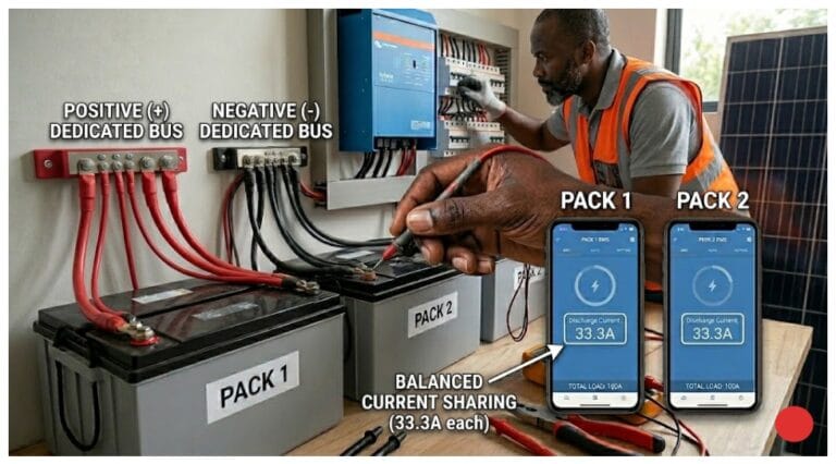
Systems with large battery banks can source several hundred amperes continuously. At these current levels, even small resistance creates significant voltage drop and heat. Battery-to-inverter cables might need to be 4/0 AWG or even parallel runs of 2/0 AWG to handle the current without excessive drop.
Parallel cable runs require careful attention to ensure current splits evenly between them. The cables must be identical length and gauge, and the terminations must be symmetrical so one path doesn’t have more resistance than the other. If one cable carries more current due to asymmetry, it will overheat while the other is underutilized.
Warranty and Liability Considerations
Undersized cables can void equipment warranties. Many inverter manufacturers specify minimum cable gauge in their installation manuals. If you install 6 AWG where the manual specifies 4 AWG minimum, and the inverter fails due to chronic low voltage operation, the warranty claim may be denied.
Read the installation manual for every component and note any cable sizing requirements. These supersede your own calculations if they’re more conservative.
From a liability standpoint: if a system underperforms or components fail prematurely due to inadequate cable sizing, and you can’t show that you followed NEC requirements and manufacturer specifications, you’re exposed. The defense against this is documentation, voltage drop calculations, derating factors applied, compliance with manufacturer specs. If you can show the math that justified your cable selection, you’re defensible even if problems arise later.
Client Communication: Selling Proper Cable Sizing
Homeowners don’t instinctively understand why you’re charging $800 for cable on a $20,000 system. “It’s just wire” is the objection. The way to address this is to explain what undersized cables cost them over the system’s life.
Show them the math: “If we use 6 AWG instead of 2 AWG here, you’ll lose 120W to heat during peak charging. Over 25 years, that’s 1,095-kWh wasted. At $0.12/kWh, that’s $131 worth of electricity you paid to generate but never used. The cable upgrade costs $220 now and saves you $131 in losses, plus it protects your $4,000 battery bank from chronic undercharging that would reduce its life by 20-30%.”
Most clients will accept this explanation if you present it clearly. The ones who insist on cheapest-possible cable despite the explanation are the ones who will call in 18 months with complaints. Document the conversation and the recommendation in your contract notes.
Competitive Differentiation
In a market where many installers compete primarily on price, doing cable sizing correctly is a way to differentiate on quality. You won’t win the race-to-the-bottom price competition, but you can position yourself as the installer who does it right and whose systems don’t need service calls for underperformance issues.
I include voltage drop calculations in every proposal, even for small systems. Most competitors don’t bother. When a client is comparing three quotes and only one of them includes detailed cable specs and voltage drop analysis, that quote looks more professional and thorough even if it’s slightly more expensive.
Universal Best Practices
Regardless of whether you’re a homeowner evaluating a system, a DIYer building one, or a professional installer, certain principles apply universally to cable sizing in solar systems. These aren’t complex engineering rules, they’re the distilled lessons from hundreds of installations and troubleshooting calls.
Design Principle 1: Minimize Cable Length First, Then Size Appropriately
The easiest way to reduce voltage drop is to not have the voltage drop opportunity in the first place. Every foot of cable you eliminate is a foot that can’t waste power or generate heat.
In practice, this means thinking about equipment placement as an electrical design problem, not just a construction convenience problem. I see installations where the charge controller is mounted on one side of the garage because that’s where the installer set up his ladder, and the batteries are on the other side because that’s where there was floor space. The result is 25 feet of unnecessary cable run that could have been 8 feet with different placement.
Before you commit to equipment locations, sketch the DC cable routing. Look for ways to consolidate equipment spatially. Can the charge controller and inverter be mounted near each other? Can the battery bank be positioned to minimize distance to both? Sometimes moving a component 10 feet eliminates 30 feet of cable routing because you can run directly instead of around obstacles.
This optimization is easiest during new construction or major retrofits where you have flexibility. In existing buildings, you work with what you have, but even then, look for opportunities. Moving an inverter from one wall to another might be a two-hour job that saves $300 in cable and improves performance for 25 years.
Design Principle 2: When In Doubt, Go Larger on Gauge
Cable sizing has an interesting asymmetry: undersizing costs you performance and safety, but oversizing costs you only money at installation. And the cost difference between adjacent wire sizes is usually modest, going from 6 AWG to 4 AWG might add $1.50/foot, which for a 20-foot run is $30.
If your calculation shows that you’re right at the edge between two gauge sizes, say, 2.8% voltage drop with 8 AWG and 2.1% with 6 AWG, choose the larger size. The performance improvement is real (0.7% less loss), and you’ve built in margin for installation realities that calculations don’t capture: slightly longer routing than expected, connections that aren’t quite perfect, future system expansion.
I’ve never had a client complain that their cables were too big. I’ve had plenty complain about cables that were too small, after the fact, when fixing it requires tearing out and replacing installed cable.
The exception to this rule is physical constraints: sometimes you genuinely can’t fit 2/0 AWG cable where 1/0 AWG would go, or the terminal lugs on your equipment can’t accept the larger wire. In those cases, you work with what fits. But absent physical constraints, err toward larger.
Design Principle 3: System Voltage Selection Sets Everything Downstream
The decision to build a 12V, 24V, or 48V system affects every cable sizing choice you make afterward. Higher voltage means lower current for the same power, which means smaller cables, less voltage drop, and less heat.
If you’re designing a system from scratch and you have any choice in the matter, bias toward higher voltage. The only reason to choose 12V is if you have loads that require 12V and you don’t want to run DC-DC converters. Otherwise, 24V is better than 12V, and 48V is better than 24V for anything above 2-3kW.
The practical impact: a 3000W inverter on a 12V system draws 250A, requiring 4/0 AWG cable for even a short run. The same inverter on a 48V system draws 62.5A, which can be handled with 4 AWG cable. That’s the difference between $12/foot and $3/foot for cable, and between a 2-inch-diameter cable and a half-inch-diameter cable in terms of physical installation.
I understand that battery availability and cost sometimes forces voltage decisions, 48V batteries are more expensive and less common in small systems. But the cable savings often offset the battery cost difference, especially if you account for the long-term performance and safety benefits.
Design Principle 4: Calculate, Don’t Estimate
I’ve met installers who size cables by “feel” based on experience. “I always use 6 AWG for charge controller to battery on systems like this.” That works until it doesn’t, and when it doesn’t, you’ve installed a system with a permanent performance handicap.
Doing the voltage drop calculation takes five minutes with an online calculator, or ten minutes manually. There’s no excuse for skipping it. The calculation tells you whether your intuition is correct, and it gives you documentation to show clients or inspectors if questioned.
Even if you’re experienced enough that your estimates are usually right, do the math anyway. Systems vary. A run that’s fine at 30A fails at 45A. A distance that works in a 48V system doesn’t work in a 24V system. The calculation catches these variations that intuition might miss.
Design Principle 5: Account for Real-World Conditions
Voltage drop calculations assume ideal conditions: cables at rated temperature, connections with zero resistance, ambient temperature at 30°C. Real installations don’t meet these assumptions.
Build margin into your design:
- Add 10-15% to measured cable lengths to account for routing variations
- If cables will be in hot environments (attics, rooftops, enclosed spaces), apply temperature derating
- Assume connections add 0.05-0.1V drop per junction point
- If the system might be expanded in the future, size cables for the expanded capacity now
This margin costs a small amount upfront but prevents marginal designs from becoming problematic in actual operation. A system designed to exactly 3% voltage drop in ideal conditions might run at 4-5% in actual use. One designed to 2% with margin will stay under 3% in the real world.
Design Principle 6: Safety Requirements Override Performance Optimization
Sometimes the calculation says you need 8 AWG, but code requires 6 AWG because of ampacity derating for temperature or conduit fill. In those cases, you install 6 AWG. Code compliance isn’t optional, and ampacity ratings exist to prevent fires.
The NEC is a minimum safety standard, not an optimal performance standard. Just because code allows something doesn’t mean it’s the best choice for performance. But where code requires something more conservative than your voltage drop calculation, you follow code.
This most commonly comes up with temperature derating in hot environments. Your voltage drop calculation might say 10 AWG is fine, but after applying correction factors for a rooftop conduit in summer, the ampacity requires 6 AWG. You install 6 AWG.
Design Principle 7: Future-Proof Where Practical
Cables are one of the few components in a solar system that you’ll never upgrade unless they fail. Panels get replaced with higher-efficiency models. Inverters get upgraded for more capacity or better features. Batteries are replaced when they reach end of life. But cables, once installed in conduit or buried underground, stay there for decades.
If there’s any possibility of system expansion, adding more panels, increasing battery capacity, upgrading the inverter, size cables for that future scenario now, even if it seems like overkill for the current system. The cost difference is minimal compared to the cost of replacing installed cable later.
I’ve seen this play out repeatedly: a homeowner installs a small system, loves it, wants to expand it two years later, and discovers that the cables from the charge controller to the battery can’t handle the increased current from additional panels. Now they have to either abandon the expansion plan or tear out and replace cable that’s only two years old. If they’d installed one gauge size larger initially, an extra $50-80, the expansion would have been straightforward.
Priority Order for Cable Investment
If budget constraints force you to make tradeoffs, here’s the priority order for where cable quality matters most:
1. Battery to inverter: This carries the highest current and the most variable loads (surge current during motor starts, etc.). This is the cable that will overheat or drop voltage first if undersized. Get this one right even if you compromise elsewhere.
2. Charge controller to battery: This carries continuous charging current, often for hours at a time during peak sun. It’s less critical than the inverter cable (lower peak current), but it’s still high-priority because voltage drop here prevents batteries from fully charging.
3. Array to charge controller: This is the longest run in many systems (panels on roof, charge controller in garage), but the current is relatively moderate and the voltage is higher (panel Vmp is typically 18-22V for a “12V” panel, not 12V). You still need to size it properly, but if you’re forced to make a tradeoff, this is where a slightly higher voltage drop percentage is least harmful.
4. Low-current circuits: Monitoring cables, communication cables, small loads, these matter for functionality but they’re not going to waste hundreds of watts if they’re slightly undersized.
Inversely, this is the priority order for troubleshooting: if a system is underperforming and you suspect cable issues, check the battery-to-inverter run first, then charge controller-to-battery, then array wiring.
The One-Time Decision With Permanent Consequences
Cable installation is not something you iterate on. You don’t install cable, test it, find it’s marginal, and easily fix it. Once cable is in conduit, buried, or routed through walls, replacing it is expensive and disruptive.
This is why I’m emphatic about getting cable sizing right the first time. It’s a decision you make once, during system design or installation, and you live with the consequences for the entire life of the system. Every other component can be upgraded, repaired, or replaced without major disruption. Cables are the permanent infrastructure.
If you’re a homeowner hiring an installer, this is why cable specs should be in your contract and why you should verify they were installed as specified. If you’re a DIYer, this is why it’s worth spending an extra hour on calculations and an extra $200 on properly sized cable. If you’re a professional, this is why cutting corners on cable to hit a price point is false economy, you’ll spend more time and money on service calls fixing the problems than you saved on installation.
The Bottom Line
Solar panels generate power. Batteries store power. Charge controllers and inverters manage power. But cables decide how much of that power actually makes the journey from source to load without being wasted as heat.
Proper cable sizing isn’t the exciting part of solar system design. It doesn’t make for good marketing copy. But it’s the foundation that everything else depends on. A system with premium panels, expensive batteries, and a top-tier inverter will underperform if the cables connecting them are inadequate. A system with mid-range components and excellent cable sizing will outperform and outlast one with the opposite priorities.
Get the cables right. Everything else is easier after that.
Conclusion
The most common question I get after explaining all of this is: “Why don’t more people know about this?”
The answer is that cable losses are invisible until they’re catastrophic. A system bleeding 5% of its power to voltage drop doesn’t throw error codes. The monitoring doesn’t show a “cable problem” alarm. The batteries charge, just not quite fully. The inverter runs, just not quite at full capacity. Everything appears functional while performance degrades slowly enough that it seems like normal aging.
This is what makes cable sizing both critically important and easy to neglect. The consequences of poor choices compound over years, but they’re never dramatic enough to force immediate attention until components start failing prematurely.
If You Remember Only Three Things
First: Voltage matters more in low-voltage systems. The same absolute voltage drop that’s barely noticeable in a 48V system will cripple a 12V system. If you’re running 12V or 24V, you cannot afford to be casual about cable sizing. The physics are unforgiving at high current.
Second: Cable sizing is permanent. You can upgrade panels, replace batteries, swap inverters. You can’t easily fix cable that’s buried, in conduit, or routed through structure. This is a one-time decision with 25-year consequences. Spending an extra $200-300 on proper cable gauging at installation is the cheapest performance optimization in a solar system.
Third: Heat is the warning sign you can see. If any cable in your system is noticeably warm during normal operation, it’s too small for the current it’s carrying. This tells you immediately that you have a problem, even if the system appears to be working otherwise.
Action Items By Audience
If you're a homeowner evaluating quotes:
- Demand specific cable gauge specifications in proposals, not vague descriptions
- Ask to see voltage drop calculations for all DC circuits
- Question any proposal with very long cable runs that could be shortened with different equipment placement
- Verify that installed cable matches what was specified before final payment
If you're a DIY installer:
- Do the voltage drop calculation for every DC circuit using actual measured routing distances
- When in doubt between two wire sizes, choose the larger one
- Test your work by measuring voltage drop under load after installation but before the system goes into service
- Don’t assume that automotive wire or household Romex is suitable for DC solar circuits
If you're a professional:
- Include voltage drop calculations in permit documentation as standard practice
- Account for temperature derating in hot environments, not just base ampacity
- Use cable sizing as a competitive differentiator, most installers don’t document this well
- Remember that manufacturer warranty claims can be denied if installed cables don’t meet minimum specifications
The Reality Check
I know that after reading 15,000 words about cable sizing, some people will still install their system with whatever wire they have left over from a previous project, or whatever’s on sale at the supply house. Human nature favors convenience and cost savings over invisible future benefits.
But if this post convinces even a few people to size cables properly, to do the calculation, buy the right gauge, route thoughtfully, and install with care, then those systems will perform better, last longer, and cost less over their lifetime than they would have otherwise.
Cable sizing isn’t glamorous. It won’t make you sound knowledgeable at parties. It doesn’t involve cutting-edge technology or exciting innovation. It’s just copper conductors moving electrons according to physics that were understood 150 years ago.
But it’s the difference between a solar system that delivers 95% of its theoretical performance for 25 years, and one that delivers 80% and degrades prematurely. Over the life of the system, proper cable sizing is worth thousands of dollars in avoided losses and prevented failures.
Final Thought
Every watt you generate costs money, in panels, in mounting hardware, in installation labor. Wasting that power in cables because you didn’t size them correctly is like paying for a 5kW array but only getting a 4.5kW array delivered to your batteries.
The solar industry has optimized nearly everything about energy generation and storage. Panel efficiency has improved from 15% to 22%. Battery chemistry has advanced from lead-acid to lithium with twice the cycle life. Charge controllers have evolved from simple PWM to sophisticated MPPT algorithms that extract every available watt from the array.
But none of that optimization matters if the cables connecting these components are dropping 5-7% of the power before it reaches its destination.
Get the cables right. The rest of the system will thank you for it.

I am Engr. Ubokobong Ekpenyong, a solar specialist and lithium battery systems engineer with over five years of hands-on experience designing, assembling, and commissioning off-grid solar and energy storage systems. My work focuses on lithium battery pack architecture, BMS configuration, and system reliability in off-grid and high-demand environments.