Introduction: The Three-Battery Disaster
Commercial installation, 45 kWh total capacity using three 15 kWh battery modules in parallel. The installer followed what seemed like straightforward logic: daisy-chain the CAN cables between batteries, connect to the inverter, power everything up. Commissioning looked perfect. All three batteries appeared on the inverter display showing individual SOC values, cell voltages visible, communication status green. Customer signed off. Job closed.
Week two, Battery 2 started showing different SOC than Battery 1 and 3. Not alarming initially, maybe 3-5% difference. Installers assumed this was normal variation. Month one, the gap widened to 8-12%. Battery 2 consistently reading higher SOC than the others. Month two, during a routine charge cycle, Battery 2 cells hit 3.62V while Battery 1 and 3 sat at 3.48V. Battery 2 BMS threw over-voltage fault and opened its contactors.
System continued operating on two batteries at reduced capacity. Customer complained about unexpected shutdowns and reduced runtime. Investigation revealed the root cause: all three batteries configured with identical CAN ID 0x01. The inverter was only receiving and processing data from Battery 1. Battery 2 and Battery 3 messages were colliding on the bus, getting corrupted, effectively invisible to the inverter.
The inverter applied Battery 1 charge voltage limit of 56.0V to the entire parallel bank. Battery 2 and 3 charged without proper CVL enforcement. Battery 2, having slightly lower internal resistance from manufacturing tolerance, accepted more current than the others and reached over-voltage first. This failure mode is especially dangerous because it develops silently, without inverter alarms, until a cell-level protection event forces a shutdown.
Resolution required reconfiguring all CAN IDs correctly, adding proper termination that was missing entirely, and implementing actual master/slave coordination. Total cost: $2,000 in diagnostic labor plus $4,000 for Battery 2 cell replacement after months of over-voltage stress. A $6,000 mistake from not understanding multi-battery CAN bus architecture.
The system appeared functional during commissioning because the physical connection worked and the inverter displayed all three batteries. But displaying battery data and actually controlling those batteries are completely different things. Multi-battery systems aren’t plug-and-play. Architecture choices determine whether batteries work together cooperatively or fight each other destructively.
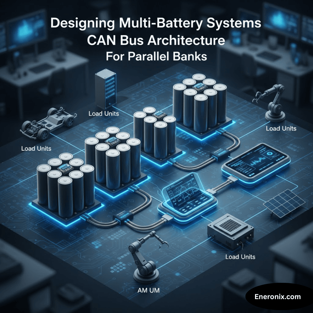
Master/Slave vs Parallel CAN Architectures

Two fundamentally different approaches exist for multi-battery communication, each with distinct tradeoffs in complexity, reliability, and inverter compatibility. Understanding which architecture your system uses determines configuration requirements and failure modes.
Master/Slave Architecture
Master/slave architecture designates one battery as the communication controller. Battery 1 becomes master, communicating with the inverter using standard Pylontech protocol messages at 0x351, 0x355, 0x356. Batteries 2 and 3 operate as slaves, communicating with the master through separate CAN messages or hardwired signals depending on BMS design. The master aggregates all data: sums total capacity, averages state of charge, calculates minimum CVL from all batteries, sums charge current limits. The inverter sees only the master, completely unaware that slave batteries exist behind it.
This approach works with any inverter because the inverter thinks it’s communicating with a single large battery. No inverter firmware modifications required. The master provides intelligent aggregation, ensuring the inverter receives composite limits that protect all batteries. Configuration is straightforward once you understand the master must aggregate properly. Troubleshooting follows clear hierarchy: verify master communication first, then check master-slave links second.
The critical disadvantage is single point of failure. If the master battery fails or loses communication, the entire system goes offline even though slave batteries remain healthy. The master must be specifically designed for this role with aggregation firmware—you cannot use three identical standard BMS units. Slaves become dependent on master commands, losing independent operation capability. Expansion requires the master supporting additional slaves, which may have firmware limits.
Parallel CAN Architecture

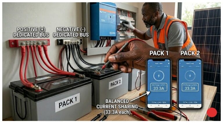
Parallel CAN architecture treats all batteries as equals. Each battery gets unique CAN ID: Battery 1 uses 0x351, Battery 2 uses 0x451, Battery 3 uses 0x551 for their respective message sets. All batteries transmit independent data on the shared CAN bus. The inverter receives separate CVL, CCL, SOC values from each battery and aggregates them in its own firmware. No master exists. Battery failure means the inverter simply stops receiving that battery’s data and recalculates using remaining batteries.
True redundancy and fault tolerance emerge from this design. One battery communication failure doesn’t kill the system, just reduces capacity proportionally. Each battery maintains full BMS capability with independent decision making. Expansion becomes simpler: add battery, assign new CAN ID, inverter detects and incorporates it automatically if firmware supports dynamic battery count.
Parallel architecture requires sophisticated inverter firmware specifically designed for multi-battery aggregation. Not all inverters support this despite marketing claims. Configuration complexity increases with ID assignment and aggregation rule verification. CAN bus traffic triples with three batteries all transmitting complete message sets. Timing conflicts can occur if batteries transmit simultaneously without coordination.
If your inverter firmware does not explicitly document multi-battery aggregation behavior with specific examples of how it processes multiple CAN IDs, assume it does not support true parallel CAN. Default to master/slave architecture or verify compatibility through actual testing before committing to the installation.
CAN ID Assignment and Message Collisions
Getting CAN IDs wrong creates silent failures that appear as battery defects rather than configuration errors. Every battery on the bus must have a unique identifier, and that identifier must match what the inverter expects for proper data reception.
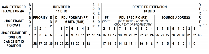
CAN messages use identifiers to determine priority and routing. Pylontech protocol uses extended 29-bit frames with base message IDs like 0x351 for CVL/CCL/DCL, 0x355 for SOC/SOH, 0x356 for voltage/current/temperature. Multi-battery systems modify these base IDs to create unique address spaces. Battery 1 might use 0x351, 0x355, 0x356 as standard. Battery 2 uses 0x451, 0x455, 0x456 by adding 0x100 offset. Battery 3 uses 0x551, 0x555, 0x556. Alternative schemes increment by 0x10: 0x351, 0x361, 0x371. The specific scheme depends on BMS firmware implementation and what the inverter expects.
Most battery systems use DIP switches on the BMS circuit board to set addressing. Physical switch positions determine the CAN ID offset. All switches OFF typically equals Battery 1 with base ID. Switch 1 ON equals Battery 2 with first offset. Switch 2 ON equals Battery 3 with second offset. The BMS manual specifies exact switch-to-ID mapping, and this must match inverter documentation exactly. Photograph DIP switch positions during installation for future reference.

The Invisible Overcharge Scenario
When two batteries share the same CAN ID, message collisions occur continuously. Both batteries attempt to transmit CVL in message 0x351 at the same instant. CAN bus arbitration protocol resolves the collision by allowing the message with lower bit values to proceed while forcing the other to retry. One battery’s data succeeds; the other gets corrupted. The inverter receives whichever message wins arbitration, creating unpredictable behavior.
If Battery 1 transmits CVL of 56.0V and Battery 2 transmits 54.4V but they share ID 0x01, the inverter might see 56.0V in one update cycle and 54.4V the next. It thinks one battery is rapidly changing limits instead of recognizing two separate batteries exist. The inverter might average the values incorrectly, use the most recent value randomly, or fault entirely depending on firmware implementation.
The invisible overcharge scenario develops when the inverter consistently receives data from Battery 1 due to arbitration priority, while Battery 2 messages get suppressed. The inverter enforces Battery 1 CVL of 56.0V across the entire parallel bank. Battery 2 wanted 54.4V to protect cells approaching voltage limit, but that message never reaches the inverter. Battery 2 cells climb to 3.60V or higher before local BMS protection disconnects.
If two batteries share a CAN ID, the system may appear functional while actively damaging cells. This warning prevents installers from dismissing ID conflicts as minor configuration details.
Verification Procedure
Verification requires systematic testing before commissioning. Power each battery individually and confirm its CAN ID with an analyzer showing expected message IDs. Document all ID assignments with physical labels on each battery and photos in commissioning records. Power all batteries together and verify the CAN analyzer shows unique message sets from each battery with no ID overlap. Check inverter display confirms all batteries appear with individual data, not just total count. Verify CVL and CCL values match expected ranges for the number of batteries installed.
Termination and Physical Layer Essentials
Termination mistakes cause roughly 60% of multi-battery communication failures. The fundamental rule is simple but frequently violated: terminate only the physical ends of the CAN bus, not every device connected to it. For complete termination troubleshooting including measurement procedures and common cable issues, see CAN Bus Physical Layer: The 60-Second Fix for Battery Communication Failures.
Correct topology for three batteries in parallel connects like this: 120Ω termination resistor at one end, Battery 1 in the middle without termination, Battery 2 in the middle without termination, Battery 3 in the middle without termination, 120Ω termination at the other end. Measuring resistance between CAN H and CAN L at any point on this bus shows 60Ω, representing two 120Ω resistors in parallel.
The most common mistake is terminating every battery. Installer logic follows: each battery is a CAN device, CAN devices need termination, therefore terminate all batteries. Three batteries with three 120Ω terminators creates parallel resistance of 40Ω. This overloads the CAN transceiver chips designed for 60Ω nominal load. Signal voltage amplitude drops below specification. Communication works marginally at short distances or low data rates but fails intermittently when cable length increases or during high inverter switching noise.
Verification procedure requires powering off the entire system for safety. Disconnect one CAN cable end to break the circuit. Use a multimeter to measure resistance between CAN H and CAN L pins at the disconnected cable end. The reading should be 60Ω ±5Ω. If incorrect, systematically locate and correct termination by checking each battery’s internal termination status and removing or adding resistors as needed to achieve exactly two 120Ω terminators on the bus.
Data Aggregation: The Make-or-Break Decision
How the inverter combines data from multiple batteries into a single virtual battery determines whether the system protects cells properly or allows damage to accumulate invisibly. Aggregation logic varies significantly between inverter manufacturers, and wrong assumptions about how this works cause most multi-battery degradation issues. Understanding how CVL, CCL, and DCL limits work individually is critical before aggregating them across multiple batteries.
The CVL Aggregation Rule: Always Use Minimum
Charge voltage limit aggregation is critical for cell protection. Battery 1 reports CVL of 56.0V with cells at 3.48V each. Battery 2 reports 55.2V because one cell reached 3.55V and the BMS reduced the limit protectively. Battery 3 reports 56.0V with cells at 3.48V. The inverter must use the minimum value of 55.2V to protect Battery 2’s high cell.
Averaging these values to 55.7V causes the inverter to charge to that voltage, forcing Battery 2 cells to 3.58V or higher, exactly the over-voltage condition the BMS tried to prevent.
What happens when aggregation fails reveals itself slowly. The inverter averages CVL when it should use minimum. Charging proceeds to 55.7V instead of the 55.2V that Battery 2 requested. Battery 2 cells climb to 3.58V during every charge cycle. After 30-60 cycles of daily over-voltage stress, capacity fade becomes measurable at 5-8%. After 90-180 cycles over three to six months, Battery 2 shows 12-15% degradation. The BMS finally throws a fault and opens contactors. System capacity drops to two batteries. Customer complains that one battery failed prematurely, blaming manufacturing defect when the actual cause was incorrect CVL aggregation in the inverter firmware.
Current Limit Aggregation: It Depends
Charge current limit requires understanding whether batteries share current equally or not. Battery 1 allows 100A based on temperature and cell conditions. Battery 2 limits to 50A because internal temperature reached 42°C and thermal protection activated. Battery 3 allows 100A normally. Naive summation suggests 250A total is safe.
In practice, current distribution depends on internal resistance. Battery 2 at higher temperature has slightly lower resistance and might accept 90A even when requesting 50A limit, while cooler batteries take 80A each. The 50A limit gets violated.
Conservative aggregation uses the minimum CCL across all batteries, applying 50A global limit to the entire bank. This protects Battery 2 but significantly underutilizes Battery 1 and 3 capability. Sophisticated systems sum individual limits to 250A theoretical but monitor actual current distribution and reduce global limit if any battery exceeds its individual CCL by more than 10%. This requires per-battery current sensing that many systems lack.
There is no universal correct aggregation method. The correct strategy depends on whether current sharing is enforced electrically through external balancing, logically through firmware control loops, or not at all. Systems without current sharing enforcement must use conservative minimum methods. Systems with active current balancing can safely sum individual limits.
Voltage Imbalance Between Parallel Banks
Parallel batteries naturally diverge over time even with perfect communication and identical initial specifications. Understanding why this happens and how communication enables early detection prevents the 8-12% capacity loss customers attribute to premature battery failure. For detailed analysis of how balancing depends on proper communication, see Why Passive Balancing BMS Fails in High-Discharge Solar Battery Systems.
Manufacturing tolerance ensures no two batteries are truly identical. Battery 1 measures 200.0Ah actual capacity after formation testing. Battery 2 measures 196.5Ah, roughly 2% lower from normal cell-to-cell variation. Battery 3 measures 202.3Ah, 1% higher. During discharge to empty, Battery 2 reaches minimum cell voltage first while Battery 1 and 3 retain 5-10Ah remaining capacity. This creates continuous drift as the weakest battery limits the pack.
Internal resistance differences compound the problem. Battery 1 total resistance measures 25 milliohms. Battery 2 measures 28 milliohms, 12% higher. Battery 3 measures 24 milliohms. When the parallel bank charges at 300A total, current distribution follows Ohm’s law inversely proportional to resistance. Battery 1 accepts 102A (34% of total). Battery 2 accepts 92A (31%). Battery 3 accepts 106A (35%). Battery 2 charges slower and discharges slower, gradually diverging in SOC from the others.
Communication-Enabled Divergence Detection
Communication enables divergence detection before damage occurs. Individual SOC monitoring shows Battery 1 at 87%, Battery 2 at 82%, Battery 3 at 89% during normal operation. The 7% spread indicates meaningful imbalance developing. Immediate action through equalization charging prevents the spread from reaching 15% where customers notice reduced runtime. For comprehensive explanation of why BMS and inverter SOC values diverge, see SOC Drift in Lithium Battery Systems: Why Your BMS and Inverter Disagree.
Cell voltage monitoring provides earlier warning if that data is accessible. Battery 2 cells at 3.58V, 3.59V, 3.61V, 3.60V during charge while Battery 1 cells sit at 3.51V, 3.52V, 3.52V, 3.51V and Battery 3 cells at 3.50V, 3.51V, 3.50V, 3.51V clearly shows Battery 2 ahead approaching over-voltage threshold requiring immediate charge rate reduction.
Temperature monitoring reveals thermal problems causing accelerated divergence. Battery 1 at 35°C, Battery 2 at 44°C which is 12°C hotter than expected, Battery 3 at 33°C. Battery 2 elevated temperature indicates internal problems like cell degradation with increased resistance, poor ventilation from blocked airflow, or external heat source nearby.
Fault Tolerance and System Degradation
What happens when one battery loses communication or suffers hardware failure determines whether a multi-battery system degrades gracefully or fails catastrophically. Architecture choices made during initial design establish the failure modes customers will experience years later. When one battery loses communication in a parallel bank, the failure mode determines whether the system degrades gracefully or fails catastrophically. For detailed analysis of BMS disconnect behavior, continuing with stale data, and hardcoded defaults, see Communication Loss Modes: How Your Battery Degrades When Communication Fails.
Master/Slave Failure Modes
Master/slave systems concentrate risk in the master battery. When a slave loses communication with the master, the master stops receiving that slave’s capacity, voltage, and limit data. The master recalculates total system parameters using only the remaining responsive slaves. If Battery 3 drops offline in a three-battery system, the master tells the inverter capacity is now 400Ah instead of 600Ah, CVL and CCL reflect only Battery 1 and 2 data. The system continues operating at reduced capacity.
If the master fails, the entire system goes offline immediately. The inverter loses all communication because it only talks to the master. Slave batteries remain healthy with full charge but cannot operate without master coordination. This represents a single point of failure requiring master battery replacement or promoting a slave to master role if firmware supports that capability.
Parallel CAN Failure Modes
Parallel CAN architecture distributes failure impact differently. Battery 2 stops transmitting due to BMS processor failure or communication hardware fault. The inverter receives messages from Battery 1 at 0x351 and Battery 3 at 0x551 but nothing from Battery 2 at 0x451. The inverter recalculates using only the two responding batteries, adjusting capacity from 600Ah to 400Ah and aggregating CVL, CCL from the working batteries only. System continues operating if the inverter firmware handles dynamic battery count properly.
Not all inverters support N-1 operation. Some inverter firmware expects a fixed battery count configured during commissioning. When that count changes, the inverter faults with ‘Battery communication error’ even though two of three batteries communicate perfectly. This converts a single battery failure into a complete system failure. Inverter selection must verify explicit support for variable battery count or N-1 redundancy capability.
Expansion Planning and Future-Proofing
Designing a two-battery system today to become a five-battery system tomorrow without complete reconfiguration requires planning during initial installation. Most expansion failures trace back to decisions made during commissioning that seemed irrelevant at the time.
Reserve CAN IDs sequentially from the start. Installing two batteries now with plans for eventual expansion to five batteries means using IDs 0x01 and 0x02, not 0x01 and 0x05. Leave IDs 0x03, 0x04, 0x05 available for future batteries. Document the ID assignment scheme in commissioning records with photographs of DIP switch positions and written notes explaining the numbering system for future installers.
Termination strategy determines expansion effort required. Initial two-battery installation places 120Ω termination at one end, Battery 1 without termination, Battery 2 with 120Ω termination at the other end. Adding Battery 3 requires removing termination from Battery 2 since it becomes a middle position, connecting Battery 3 in series, and adding termination to Battery 3 as the new end position. Using removable termination plugs instead of internal jumpers simplifies this process.
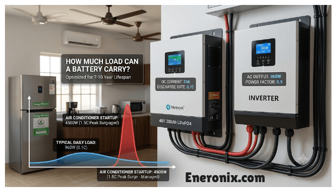
Inverter capacity planning must account for expanded current requirements. Two batteries at 200Ah each provide 400Ah total with maximum charge current around 200A at 0.5C rate. Five batteries provide 1000Ah with maximum charge current potentially reaching 500A. Verify the inverter DC input rating supports 500A continuous. Check DC breaker sizing rated for expanded ampacity. Verify cable ampacity from batteries to inverter handles 500A with acceptable voltage drop.
Commercial System Case Study: 200kWh Installation
Real commercial installation demonstrates multi-battery complexity at scale. Eight battery modules totaling 200 kWh usable capacity, each module providing 25 kWh at 48V nominal. Two 100 kW hybrid inverters, each managing four batteries through independent CAN buses. Master/slave architecture with Battery 1 and Battery 5 designated as masters. Total system capability: 200 kWh storage, 200 kW continuous charge and discharge.
Configuration complexity increased exponentially with eight batteries. Initial installation mistake had all four batteries on Bus A configured with ID 0x01 because the installer assumed master/slave meant only the master needed unique ID. Symptom appeared as slave batteries not responding to master commands. Fix required opening all enclosures, reconfiguring slaves to IDs 0x02, 0x03, 0x04.
Termination presented the second major commissioning error. Installer terminated all eight batteries. Measuring bus resistance showed 15Ω instead of the required 60Ω. Communication worked intermittently during low power operation but failed consistently during high-rate charge above 150A when inverter switching noise peaked. Removing six terminators brought resistance to 60Ω and stabilized communication completely.
Cost of configuration mistakes totaled $2,600 in avoidable issues. Initial termination error required 8 hours diagnostic time at $100 per hour equaling $800 labor cost. Battery connector corrosion needed 4 hours diagnosis totaling $600. Battery imbalance investigation consumed 12 hours totaling $1,200. Every issue traced back to fundamentals: proper ID assignment, correct termination, appropriate aggregation logic, and environmental protection.
Conclusion
Multi-battery CAN bus architecture is not complex, but it is unforgiving of configuration mistakes. The difference between a system that operates reliably for 15 years and one that damages batteries in 6 months comes down to three fundamentals: unique CAN ID assignment, proper 60Ω termination at bus ends only, and correct aggregation using minimum CVL to protect the weakest cell.
Master/slave architecture works with any inverter and provides clear single point of control, but creates single point of failure when the master battery fails. Parallel CAN architecture provides true redundancy and fault tolerance, allowing the system to continue operating with any battery offline, but requires inverter firmware explicitly designed for multi-battery aggregation.
Parallel batteries naturally diverge over time from manufacturing tolerance, internal resistance differences, and temperature variation. Communication enables early detection through individual SOC and voltage monitoring before divergence reaches the 10-15% threshold where customers notice reduced capacity. Weekly monitoring with action at 5% spread prevents what appears to be premature battery failure but is actually correctable imbalance.
Systematic diagnosis follows the same layer-by-layer approach as single-battery troubleshooting covered in BMS-Inverter Communication Troubleshooting: Proven Solutions to Fix Connection Failures: physical layer verification of termination and connections first, protocol layer confirmation of unique IDs and message presence second, data layer validation of reasonable values and proper aggregation third.
The fundamental insight is that multi-battery systems fail silently from configuration errors that create no immediate symptoms. Spending 2 hours during commissioning verifying IDs, termination, and aggregation prevents $6,000+ mistakes months later.
For complete context on communication mechanisms, physical layer troubleshooting, and protocol implementation that underlies multi-battery architecture, see the main guide on Understanding Inverter Battery Communication Protocols in Modern Solar Systems.
Commissioning Verification Checklist
- Power each battery individually, verify CAN ID with analyzer or inverter display
- Measure termination: 60Ω ±5Ω with one cable end disconnected
- Power all batteries, verify unique messages from each on CAN bus
- Check inverter shows all batteries with individual data
- Verify CVL/CCL values match expected for battery count
- Monitor SOC divergence weekly, act when spread exceeds 5%
- Document all DIP switch positions, cable routing, ID scheme with photos

I am Engr. Ubokobong Ekpenyong, a solar specialist and lithium battery systems engineer with over five years of hands-on experience designing, assembling, and commissioning off-grid solar and energy storage systems. My work focuses on lithium battery pack architecture, BMS configuration, and system reliability in off-grid and high-demand environments.