Introduction
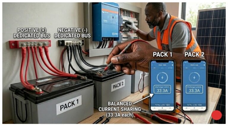
Customer calls complaining the system isn’t working right. Battery only charges at 30 amps even though the inverter is rated for 100 amps continuous. They paid for 100 amps, they want 100 amps. System must be broken.
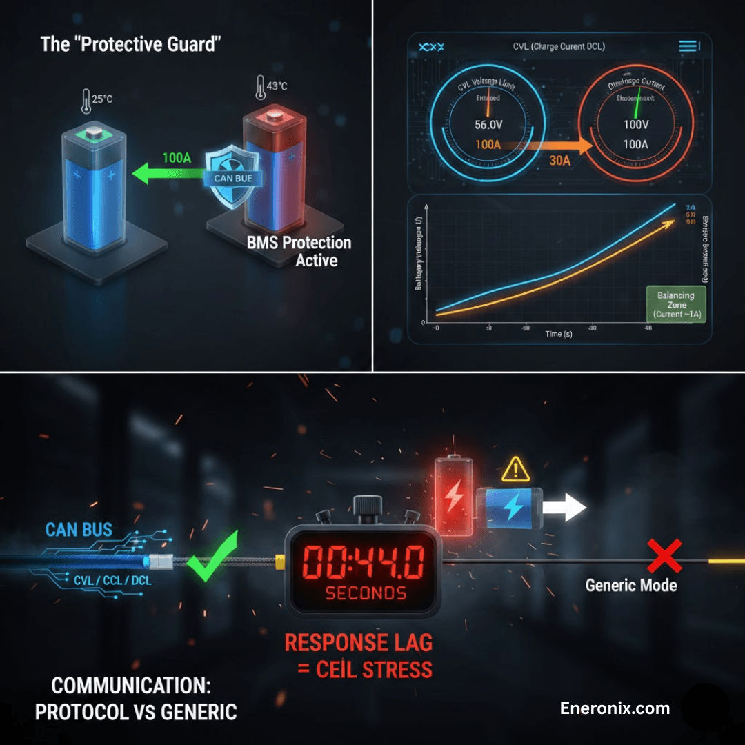
You check the inverter display remotely. It shows CCL equals 30 amps. The inverter is doing exactly what it’s supposed to do, limiting charge current to what the BMS requests. You check the BMS data. Pack temperature reads 43 degrees Celsius. The BMS reduced charge current limit to 30 amps to prevent thermal stress. At 43 degrees, charging at 100 amps would push temperatures into the 50 degree range where accelerated aging occurs. The BMS is protecting the cells.
Customer sees a broken inverter delivering 30% of rated power. Reality is proper protection working exactly as designed. The difference is understanding what CVL, CCL, and DCL actually do.

These three parameters are transmitted from BMS to inverter every single second. Charge Voltage Limit tells the inverter the maximum pack voltage to apply. Charge Current Limit tells the inverter the maximum charge current to deliver right now. Discharge Current Limit tells the inverter the maximum discharge current allowed right now. These aren’t static specifications printed on a datasheet. They’re dynamic limits recalculated continuously based on cell voltage, temperature, state of charge, imbalance, and aging state.
Understanding these three numbers explains most system behaviors that customers and installers call problems. Slow charging is often CCL reduction for thermal or voltage protection. Reduced discharge power is DCL dropping because cells are approaching empty or too cold. Charging that stops “early” is CVL reduction protecting a high cell from over voltage.
These aren’t malfunctions. They’re the control system doing its job. This post explains how these limits are calculated, why they change, what happens when inverters don’t respond properly, and how to verify the system is working correctly.
What CVL, CCL, and DCL Actually Control
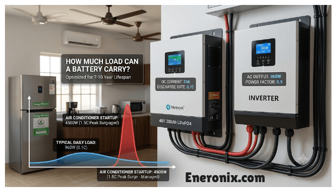
Charge Voltage Limit controls the maximum pack voltage the inverter applies during charging. For a 16S LFP pack, typical CVL is 56.0 volts (3.50 volts per cell), but it ranges from 54.4 volts to 56.8 volts depending on cell state. Early in the charge cycle when cells sit at 3.30 volts, CVL might be 56.0 volts allowing normal charging. As cells approach full with the highest cell reaching 3.55 volts, CVL drops to 55.2 volts to slow current flow and protect that high cell. If significant imbalance is detected, CVL drops further. Temperature also affects it. Cold reduces CVL slightly, excessive heat reduces it more. The inverter should track this changing voltage limit every second.
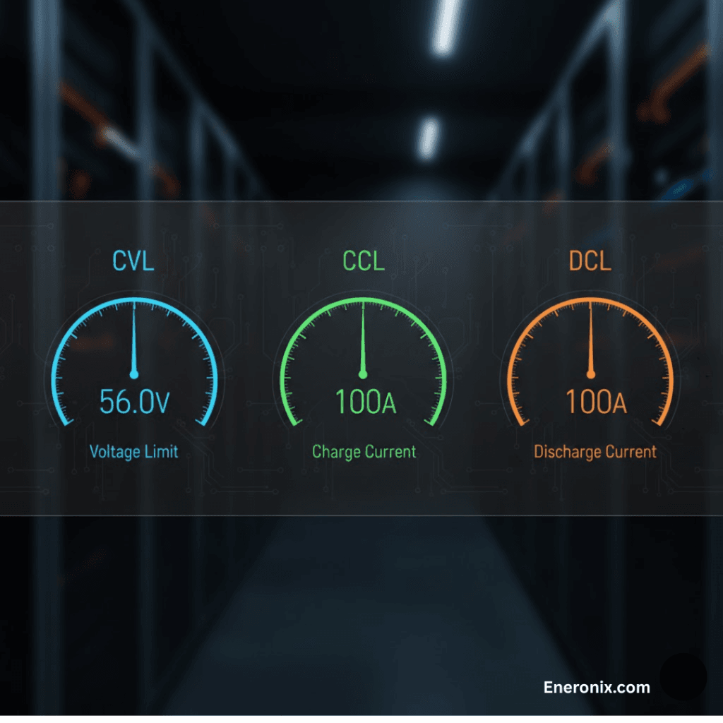
Charge Current Limit controls maximum charge current in amps the BMS will accept right now. For 200 amp-hour cells, typical maximum is 100 amps (0.5C rate), but CCL ranges from zero to over 100 amps depending on conditions. At 3.30 volts per cell and 25 degrees Celsius, CCL equals 100 amps (full capability). As cells approach 3.50 volts during the top 10% of charge, CCL tapers to 20 amps for absorption phase. Very near full at 3.55 volts, CCL drops to 2 amps or less for final balancing. Temperature affects CCL significantly.
At 45 degrees Celsius, CCL might drop to 50 amps for thermal protection. At 5 degrees Celsius, CCL drops to 10 amps or lower to prevent lithium plating on the anode. The top balance phase requires extremely low CCL, often under 1 amp. If the inverter cannot deliver currents this low, balancing coordination fails.
Discharge Current Limit controls maximum discharge current allowed right now. Similar dependencies as CCL: voltage, temperature, state of charge, and imbalance all factor in. At 3.25 volts per cell and 25 degrees, DCL equals 100 amps for full capability. As cells approach 3.00 volts near empty, DCL drops to 20 amps to reduce stress and prevent voltage collapse. At 2.90 volts approaching damage threshold, DCL drops to zero or near zero. Emergency scenario: minimum cell hits 2.50 volts and BMS immediately sends DCL equals zero amps to stop discharge before permanent damage occurs.
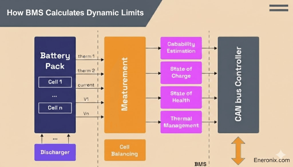
How BMS Calculates Dynamic Limits
The BMS monitors every cell voltage continuously, typically sampling at 1 to 10 Hz depending on implementation. For CVL calculation, it identifies the highest cell voltage. If the highest cell sits at 3.55 volts while others average 3.45 volts, significant imbalance exists. Current pack voltage might be 55.4 volts. The BMS calculates what CVL prevents the high cell from going higher.
The highest cell contributes 3.55 volts. The other 15 cells contribute 55.4 minus 3.55 equals 51.85 volts, averaging 3.46 volts each. Setting CVL to 55.2 volts (just 0.2 volts above current) stops voltage rise and protects that high cell from reaching 3.60 volts or beyond.
CCL reduces as the highest cell approaches full charge. At 3.48 volts, CCL might drop to 20 amps. At 3.50 volts, CCL becomes 5 amps. At 3.52 volts, CCL drops to 1 amp or zero. This taper prevents over voltage while allowing charge to complete and giving balancing resistors time to equalize cells. DCL works similarly but monitors the lowest cell. At 3.10 volts, DCL might be 50 amps. At 3.00 volts, DCL drops to 20 amps. At 2.90 volts, DCL becomes 5 amps. At 2.80 volts, DCL hits zero to prevent over discharge damage.
Read About: Testing and Calibrating Smart Batteries
Temperature adjustments happen simultaneously. At 25 degrees Celsius, both CCL and DCL operate at full capability (typically 0.5C, so 100 amps for 200Ah cells). High temperature triggers thermal protection. At 45 degrees, limits drop to 50 amps (0.25C). At 50 degrees, limits become 20 amps or lower. At 55 degrees, limits hit zero as emergency thermal shutdown approaches.
Cold temperature primarily affects CCL to prevent lithium plating. At 5 degrees Celsius, CCL drops to 20 amps (0.1C). At zero degrees, CCL becomes 5 to 10 amps. Below zero degrees, most BMS set CCL to zero because charging at freezing temperatures plates metallic lithium on the anode, permanently reducing capacity and creating internal short circuit risk. DCL is less affected by cold since discharge doesn’t create plating risk, though internal resistance increases and performance drops.
Inverter Response Time
Inverter manufacturers claim real-time limit tracking, immediate response to BMS commands, and dynamic charge control. Field measurements tell a different story. When the BMS sends a new CVL at time zero, the inverter receives the message, validates the checksum and data format, and updates its internal setpoint. This takes 0.5 to 1 second.
The voltage control loop then begins adjusting output, requiring another 1 to 2 seconds for the control algorithm to calculate new duty cycles and modify PWM signals. Output voltage settles at the new setpoint after 2 to 3 seconds total. Current finally drops to match the new limit after 3 to 5 seconds from when the BMS originally sent the message.
Read this: Distributed Voltage and Current Control documentation
This 3 to 5 second gap is where cell damage occurs. Emergency CVL reduction scenario: one cell hits 3.60 volts approaching the 3.65 volt damage threshold. The BMS drops CVL from 56.0 volts to 54.4 volts as an emergency reduction. The system is charging at 50 amps when the limit gets sent. The inverter takes 4 seconds to respond. Energy pushed during this lag equals 50 amps times 55 volts times 4 seconds divided by 3600, approximately 30 watt hours.
Impact depends entirely on cell size. A 280 amp hour cell has 896 watt hour nominal capacity. Thirty watt hours represents 3.3% of capacity, probably tolerable as a one-time event. A 100 amp hour cell has 320 watt hour capacity. Thirty watt hours is 9.4% of capacity. Voltage rise is significant. The cell the BMS tried to protect at 3.60 volts reaches 3.62 to 3.65 volts before current actually stops.
Response is slow because of control loop time constants inherent to stable operation. PI controllers (proportional-integral, the standard for power electronics) need time to settle without oscillation. Typical inverter current control has a 1 to 2 second time constant. Voltage control has 0.5 to 1 second time constant. These aren’t bugs or poor implementation. They’re necessary for preventing instability and oscillation that would damage components or trip protection circuits.
What Happens When Inverters Ignore Limits
Communication loss causes the inverter to fall back to default settings. Default CVL for generic lithium battery type is often 57.6 volts (3.60 volts per cell for 16S). The BMS wanted 56.0 volts (3.50 volts per cell). Every charge cycle now terminates 0.1 volts per cell higher than intended. This might seem minor but daily overcharge by 0.1 volts per cell accelerates SEI layer growth and capacity fade. Months one through three show no visible symptoms.
Months four through six reveal 5% to 10% capacity loss. Months six through twelve reach 10% to 15% loss and the customer complains. Cell inspection shows no obvious damage like swelling or leakage, just premature aging that appears normal except for the accelerated timeline. The root cause, communication loss leading to wrong default CVL, sits buried in logs nobody checked.
CCL being ignored breaks balancing and causes thermal stress. The BMS requests CCL equals 2 amps for top balance coordination. The inverter has a 5 amp minimum charge current floor and delivers 5 amps regardless of the request. Voltage rises 2.5 times faster than the BMS calculated. The balancing window from 3.48 to 3.50 volts gets passed in 8 minutes instead of the intended 20 minutes. Balancing resistors don’t have enough time to equalize cells.
Imbalance persists and worsens monthly. In a thermal stress scenario, pack temperature reaches 44 degrees and the BMS drops CCL to 30 amps for protection. The inverter ignores this and continues at 80 amps. Temperature climbs to 48 degrees. The BMS is forced to open contactors as emergency over temperature protection triggers. Contactor opens under 80 amp load causing arcing damage.
Also Read: CAN Bus Physical Layer: The 60-Second Fix for Battery Communication Failures
DCL being ignored causes cell over discharge. Minimum cell voltage hits 2.50 volts and the BMS sends DCL equals zero amps immediately. The inverter current control loop has a 2 second time constant. Thirty amps continues for 2 more seconds. Sixty watt hours get extracted from a cell already at damage threshold.
Cell capacity drops permanently. This happens occasionally when customers use full available capacity. Each event removes 1% to 2% capacity. After 10 events over a year, 10% to 20% capacity is gone, appearing as premature aging when the actual cause was repeated over discharge from DCL response lag.
Proper Limit Implementation
Fast response time is the foundation of proper limit tracking. Target performance has CVL, CCL, or DCL changes triggering inverter response within 1 second. Current settles at the new value within 2 seconds maximum. Voltage settles within 2 seconds. Total lag stays under 2 seconds from limit change to actual measured response.
This level of performance is rare in residential systems. You find it in industrial and commercial installations where BMS and inverter were co-developed and tested as an integrated product rather than mix and match components claiming compatibility.
True zero current capability matters critically for top balance coordination. Balancing requires current below 1 amp, ideally zero amps while holding voltage constant. If the inverter minimum charge current is 5 amps, balancing coordination fails regardless of what the BMS requests. Good implementation can hold CVL voltage with zero current flow, entering true constant voltage phase. The BMS commands CCL equals zero amps while maintaining CVL at balancing voltage. The inverter holds voltage and delivers zero current. Balancing continues with resistors slowly equalizing cells without new charge current interfering. When balancing completes and cells converge, the BMS resumes normal CCL and charging continues or terminates.
Also Read: Inverter Battery Communication Protocols in Modern Solar Systems
Limit change logging provides the data needed for diagnosis and warranty claims. Every CVL, CCL, and DCL value received gets logged with timestamp. Actual voltage and current output at that same timestamp gets logged alongside. Comparison shows whether the inverter tracked limits or diverged. This matters for post failure analysis showing what the BMS was requesting versus what the inverter actually delivered. Warranty claims depend on this proof of fault allocation. Performance optimization uses the data to identify control loop tuning issues or communication delays.
Validation without override means the inverter checks BMS limits for plausibility but doesn’t silently ignore them. CVL equals 56.0 volts with pack voltage at 52.0 volts and cells at 3.25 volts is plausible. CVL equals 56.0 volts with pack voltage at 49.0 volts and cells at 3.05 volts is implausible, indicating BMS error or corrupted message. Proper response logs the implausible data, alerts the user, and uses conservative fallback like 54.0 volts temporarily rather than ignoring all BMS data permanently.
Monitoring Limits in the Field
During commissioning at 50% SOC and 25 degrees Celsius, CVL should read near nominal value (56.0 volts for LFP). CCL and DCL should be near maximum capability, typically 0.5C or 100 amps for 200 amp hour cells. For dynamic response verification, initiate a charge cycle and watch CVL and CCL behavior during the top 10% of charge. CVL should stay steady or drop slightly if cells are imbalanced. CCL should taper from 100 amps down to 20 amps, then 5 amps, then approaching zero as cells near full.
If CCL stays at 100 amps all the way to charge termination, taper is not working and balancing will fail. Temperature response check requires heating or cooling the pack deliberately if accessible, then verifying CCL and DCL reduce at temperature extremes. Alternatively, commission during a cold morning and observe CCL lower than it would be at midday temperatures.
Also Read: SOC Drift in Lithium Battery Systems: Why Your BMS and Inverter Disagree
Signs that dynamic limits are not working appear as specific symptoms. Constant charge current to 100% SOC means current should taper in the top 5% but stays at 100 amps until charging terminates. This indicates CCL taper is failing. Growing cell imbalance shows monthly voltage spread increasing from 50 millivolts to 100 millivolts to 150 millivolts over time. This indicates balancing is not working, often caused by CCL not dropping low enough at the top of charge.
System limiting at the same current regardless of conditions, always 50 amps whether cold or hot, empty or full, indicates the inverter is using static limits and ignoring dynamic BMS values. Premature capacity fade of 10% to 15% loss in 6 to 12 months happens too fast for normal LFP aging and often results from chronic overcharge with CVL too high or over discharge from DCL being ignored.
Configuration for Optimal Limit Tracking
Battery type selection in the inverter must match the BMS protocol exactly. Select Pylontech CAN or the specific protocol the BMS uses, not generic Lithium mode. Generic lithium modes often use voltage-only control and ignore dynamic limits transmitted over CAN. The inverter treats the battery as a dumb device with no communication capability and relies entirely on measured pack voltage for charge control decisions.
Communication timeout setting determines how long the inverter waits before declaring communication lost. Set to 10 to 15 seconds to allow recovery from transient glitches caused by EMI or brief cable issues. Too short under 5 seconds creates nuisance disconnects every time electrical noise corrupts a few messages. Too long over 30 seconds means the inverter continues using stale limits for too long after sustained communication failure, potentially causing damage before fallback protection activates.
Default fallback values matter when communication fails and the inverter must operate without BMS guidance. Set these conservatively. CVL should be 54.4 volts, below normal operating voltage but safe for all conditions. CCL and DCL should be 0.3C, conservative enough to prevent thermal or electrical stress but high enough to remain functional. Avoid defaults that match maximum ratings. The defaults exist for fault conditions where conservative operation prevents damage until communication restores or someone investigates.
BMS settings, if configurable, control limit calculation aggressiveness. Conservative mode drops limits at the first sign of stress, providing high reliability with slightly lower performance. Aggressive mode allows operation closer to limits, providing higher performance with slightly elevated risk. Most installers should use factory defaults, which are usually moderate. Temperature thresholds need verification for the local environment. Cold climates might lower the cold charge cutoff to allow charging at zero degrees Celsius with very slow CCL. Hot climates need verification that high temperature cutoff is appropriate, typically 45 to 50 degrees.
Enable detailed logging beyond basic communication status. Log actual CVL, CCL, and DCL values, not just a green light saying communication OK. Log actual output voltage and current for comparison. Log limit change events with reasons if the BMS provides them. Set alerts for CCL or DCL at zero for more than 5 minutes, cell voltage spread exceeding 100 millivolts, and temperature extremes triggering limit reductions.
Troubleshooting Limit-Related Problems
When the inverter appears to ignore limits, first verify communication is actually working. Check CAN bus physical layer including termination resistance and cable integrity. Check the inverter display to see if it shows CVL, CCL, and DCL values received from the BMS. If the display shows these values, communication works and the problem is inverter response or configuration. If the display does not show values or shows zeros, fix communication before troubleshooting limit tracking.
Check inverter configuration settings. Verify protocol selection matches the BMS type exactly. Confirm that ignore BMS limits or similar override settings are disabled. Look for manual CCL or DCL overrides that an installer may have set previously. These settings defeat all dynamic protection and cause the symptoms customers report as performance problems.
Measure actual inverter response time by watching CVL change during a charge cycle and timing how long inverter voltage takes to follow the new limit. If response exceeds 5 seconds consistently, the inverter control loop is too slow. This may require firmware update if available or choosing a different inverter model for future installations. Some inverters simply cannot respond fast enough for proper cell protection.
CCL taper failure has two possible causes. Access BMS display or logs during the top 5% of charge to verify the BMS is actually sending taper values. CCL should drop from 100 amps to 50 amps to 20 amps to 5 amps to zero amps. If BMS CCL stays at 100 amps throughout, the BMS has a configuration problem or firmware bug. If BMS CCL tapers correctly but inverter current does not follow, the inverter has a response issue or minimum current floor preventing low current operation.
Temperature compensation failure requires checking that BMS temperature sensors work correctly. Verify temperature display shows realistic values, not stuck at 25 degrees or reading negative 40 degrees indicating sensor failure. Heat the pack deliberately using safe methods and watch whether CCL drops at 40 degrees compared to 25 degrees. A 20% to 50% reduction is normal. If CCL does not change with temperature, the BMS is not implementing temperature compensation. If the BMS sends reduced CCL but the inverter continues at high current, the inverter is ignoring limits due to configuration or communication problems.
Conclusion
What often appears to customers as a charging or power limitation is, in reality, the system operating exactly as designed. When a battery will not charge above 30 amps despite a 100 amp inverter rating, the cause is typically not a fault but an intelligent response. If the BMS detects elevated pack temperature such as 44 °C, it will reduce the Charge Current Limit (CCL) to protect the cells from thermal stress and accelerated aging. The inverter following this command is evidence of proper communication and healthy system behavior, not underperformance.
Dynamic limits exist to prevent specific and well understood damage mechanisms. Charge Voltage Limits (CVL) protect against over voltage cell damage. Reductions in CCL and Discharge Current Limit (DCL) at high temperatures reduce the risk of thermal runaway and long term capacity loss. In cold conditions, CCL reduction prevents lithium plating, which permanently degrades capacity and increases internal short circuit risk. At low cell voltage, DCL reduction prevents over discharge damage. Together, these limits continuously adapt the system to real time conditions, something fixed datasheet based limits cannot achieve.
Static specifications assume ideal conditions that rarely exist in the field. A charge rate that is safe at 25 °C may be damaging at 45 °C. A voltage limit that works with well balanced cells may cause harm when one cell drifts higher than the rest. Dynamic limits account for temperature, cell balance, and aging in real time, enabling safe operation across a wide range of operating scenarios.
When expected limits are not being followed, the root cause is usually integration related rather than electrochemical. Communication wiring, protocol configuration, inverter settings, and response time should be verified first. The inverter should react to BMS limits within 5 seconds, ideally within 2 seconds, and installer overrides should never defeat BMS protections. Reviewing logged limit values alongside cell voltage spread and temperature data confirms whether the system is responding appropriately to actual conditions.
Ultimately, the difference between a reliable battery system and a problematic one is not higher static ratings, but correct implementation of dynamic limits. A system that transmits BMS limits accurately, responds quickly, logs data, and adapts continuously will deliver longer life, safer operation, and more predictable performance over time.

I am Engr. Ubokobong Ekpenyong, a solar specialist and lithium battery systems engineer with over five years of hands-on experience designing, assembling, and commissioning off-grid solar and energy storage systems. My work focuses on lithium battery pack architecture, BMS configuration, and system reliability in off-grid and high-demand environments.