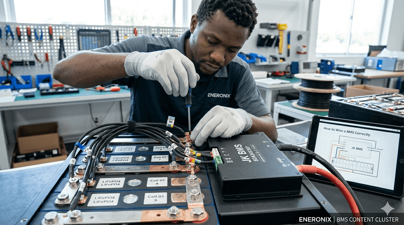
How to Wire a BMS Correctly Without Destroying It
The BMS is the most expensive small component in a DIY LiFePO4 battery build. It is also the component most commonly destroyed during the first wiring attempt.
The failure mode is almost always the same. Someone connects the power cables first, then tries to connect the cell tap wires with the BMS already powered up. Or they connect the tap wires in the wrong order because they did not read the specific diagram for their BMS model. In both cases, the result is immediate and permanent damage to the cell monitoring IC inside the BMS. The BMS needs to be replaced. The pack needs to be disassembled for rewiring.
Avoiding this is not difficult, but it requires following a specific sequence. This guide gives you that sequence, explains exactly why each step is in the order it is, covers every terminal on a typical JK BMS with what connects to it, provides the cable sizing calculations, and documents the seven wiring mistakes with the engineering reason behind each one.
Read this article before touching a BMS with a screwdriver. The 30 minutes this takes will save you the cost of a replacement BMS and two days of pack disassembly.
TL;DR
What this covers: complete BMS wiring procedure for a 16S LiFePO4 pack, from cell tap wires to RS485 communication, with the connection sequence that prevents IC damage. Who it is for: DIY battery builders and solar installers wiring a BMS for the first time or troubleshooting a failed first power-up. Key takeaways: - Cell tap wires must be connected in exact order BEFORE B+ is connected. Wrong order permanently destroys the BMS monitoring IC. - The power-up sequence is: tap wires, thermistors, B-, B+. Not B+ first. - RS485 communication requires four things: correct polarity, GND wire, correct baud rate, and correct battery type in inverter settings. - A pre-charge circuit is mandatory. Inverter capacitor inrush without one damages the BMS over time. Estimated read time: 14 to 18 minutes.
Terminal Identification: What Every Terminal Does
Before connecting anything, understand what each terminal on the BMS does. Every terminal has a specific function and connects to a specific point in the circuit. Connecting the wrong thing to any terminal causes either immediate hardware damage or silent operational problems that show up weeks later.
| Terminal | Name | What Connects Here | Critical Notes |
| B+ | Battery positive (cell side) | Connect to the most positive point in the series string: the positive terminal of the last cell (Cell 16 in a 16S pack). This is the raw cell voltage before any MOSFET switching. | NEVER leave unconnected with the pack assembled. Floating B+ means the BMS has no reference voltage and may behave unpredictably. |
| B- | Battery negative (cell side) | Connect to the most negative point in the series string: the negative terminal of the first cell (Cell 1 in a 16S pack). The current shunt is typically on this line inside the BMS. | B- is the current measurement path. High resistance at this connection causes current measurement errors and SOC drift. |
| P+ | Pack positive (load/charge side) | Connect to the inverter battery positive terminal (via fuse and pre-charge circuit). All load and charge current flows through this terminal on a common-port BMS. | P+ is switched by the MOSFET bank. When BMS protection trips, P+ is disconnected from B+. |
| P- | Pack negative (load/charge side) | Connect to the inverter battery negative terminal. Often the same physical terminal as B- on common-port designs. | On some BMS models, P- and B- are the same terminal. On others they are separate. Check the specific wiring diagram. |
| C+ | Charge positive (separate-port only) | On separate-port BMS: connect charge sources (MPPT, grid charger) to this terminal. Do NOT connect loads to C+. | Mixing C+ and P+ connections reverses the protection logic. Discharge faults will open the charge path instead of discharge. |
| Balance wires (B0 to B16) | Cell voltage tap connections | Connect in sequence from most negative cell junction (B0 = B-) through each cell junction to the most positive (B16 = B+). The exact wire numbering varies by BMS manufacturer. | CRITICAL: Wrong order permanently damages the BMS cell monitoring IC on first power-up. Verify against the specific BMS wiring diagram. |
| T1, T2 (thermistors) | Temperature sensor connections | Connect NTC thermistor probes to the designated thermistor pins. Mount probes in physical contact with cell surfaces and MOSFET board. | Do not leave thermistor connections floating. A disconnected thermistor reads as open-circuit, which many BMS units interpret as maximum temperature and trigger OTP immediately. |
| RS485 A, B, GND | Communication interface | A to inverter RS485 A. B to inverter RS485 B. GND to inverter GND. Use twisted pair cable. Route separately from power cables. | A and B polarity reversal prevents communication but does not damage hardware. If no communication: swap A and B, then retry. |
| KEY TAKEAWAY | Read the wiring diagram for your specific BMS model before connecting any wire. Not a generic diagram from a YouTube video. The specific diagram for your model. Different BMS variants number their tap wire channels differently. |
Cell Tap Wires: The Most Critical Connection in the Entire Build
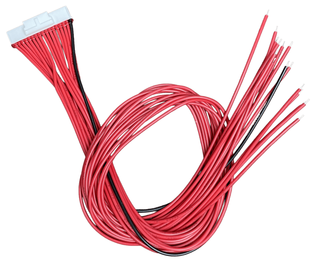
The cell tap wires are the thin signal wires that connect each cell junction in the series string to the BMS cell monitoring IC. They carry only milliamps of signal current. But getting their connection order wrong permanently destroys the BMS.
Here is the engineering reason why this matters so much.
The BMS cell monitoring IC measures the voltage of each cell by reading the differential voltage between adjacent tap wire connections. The voltage between tap B0 and tap B1 gives the BMS the voltage of Cell 1. The voltage between B1 and B2 gives Cell 2. And so on.
Each input channel on the IC is rated for a maximum differential input voltage: typically 5V for most lithium cell monitoring ICs. A LiFePO4 cell at full charge presents 3.65V across one channel. That is well within the 5V limit.
Now imagine tap wire B1 is connected to the wrong position, say it is connected where B5 should be. The IC’s Channel 1 input now sees the voltage difference between B0 (0V reference) and the Cell 5 positive junction (approximately 16V above B0 in a series string). That is 16V on an IC channel rated for 5V. The IC is destroyed in microseconds. No protection circuit can respond fast enough.
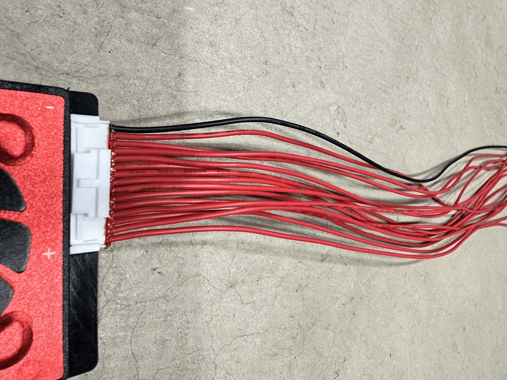
| WHY THIS HAPPENS IN THE FIELD | Most BMS units ship with tap wires bundled together in a loose harness. The wires look identical. They are usually colour-coded but the colour sequence varies by manufacturer and is not standardised. An installer in a hurry connects them in the bundle order rather than counting from B0. Three wires are in the right positions. Two are transposed. B+ is connected. The BMS IC is dead. This is not a rare failure. It happens on a significant proportion of first-time BMS installations. |
The Correct Cell Tap Wire Connection Procedure
| Tap Wire | Physical Connection Point | Engineering Function |
| B0 (or C0) | Pack B- terminal / Cell 1 negative | This is the most negative point in the entire series string. Connect the B0 tap wire here first. This establishes the 0V reference for all subsequent cell voltage measurements. |
| B1 | Junction of Cell 1 positive and Cell 2 negative | This junction is at approximately 3.2V above B0 on a balanced pack. The BMS measures the voltage between B0 and B1 to get Cell 1’s voltage. |
| B2 | Junction of Cell 2 positive and Cell 3 negative | Approximately 6.4V above B0. BMS measures B1 to B2 for Cell 2 voltage. |
| B3 to B15 | Each subsequent cell junction | Continue in sequence. B3 is the junction between Cell 3 positive and Cell 4 negative. Each subsequent Bn connects to the next cell junction up the string. |
| B16 (or C16) | Pack B+ terminal / Cell 16 positive | This is the most positive point in the string, at approximately 51.2V above B0 on a balanced 16S pack. The BMS measures B15 to B16 for Cell 16 voltage. |
The practical procedure for a 16S pack:
- Lay out all tap wires (B0 through B16) on the workbench in numerical order. Some BMS models label them B0 to B16. Others label them C0 to C16 or B1 to B17. Consult the diagram.
- Identify B0: this is the tap wire that connects to the most negative cell terminal in the string. The negative terminal of Cell 1. Also the B- terminal of the pack.
- Connect B0 to the Cell 1 negative terminal. This is the same physical point as the B- power connection.
- Connect B1 to the junction between Cell 1 positive and Cell 2 negative. This junction is the first busbar connection in the series string.
- Continue in sequence through B2 at the Cell 2/3 junction, B3 at Cell 3/4, through to B15 at the Cell 15/16 junction.
- Connect B16 to the Cell 16 positive terminal. This is the same physical point as the B+ power connection.
- Before connecting B+, verify each tap wire against the diagram one more time. This verification takes 3 minutes and prevents an expensive mistake.
| VERIFICATION METHOD | After connecting all tap wires and before connecting B+, use a multimeter to measure the voltage between B0 and each subsequent tap wire. B0 to B1 should read approximately 3.65V. B0 to B2 should read approximately 7.30V. B0 to B8 should read approximately 29.2V. B0 to B16 should read the full pack voltage. If any reading is significantly wrong, a tap wire is misconnected. Find and fix it before connecting B+. |
Power Connection Sequence: The Order That Prevents IC Damage
Once tap wires are verified, the power connections follow in a specific sequence. The sequence exists to ensure the BMS always has valid voltage references before it reads any cell voltages, and to prevent current surges that damage components.
| Step | Action | Engineering Rationale | Stop Condition |
| 1 | Connect all cell tap wires (B0 through B16) in order | The BMS IC needs voltage references established before power is applied. Tap wires must be correct before B+ is connected. | STOP if any tap wire is in the wrong position. Fix before proceeding. |
| 2 | Connect thermistors to T1 and T2 terminals | Floating thermistors on some BMS models trigger immediate OTP faults on power-up. | Thermistors must be in contact with cell surfaces, not floating in air. |
| 3 | Connect B- cable to BMS B- terminal | Establishes the negative reference for the BMS power supply circuit. | B- first, before B+, to avoid a floating reference state. |
| 4 | Connect B+ cable to BMS B+ terminal (with fuse in place) | Powers up the BMS for the first time. The BMS now reads all 16 cell voltages through the tap wires. | Open the BMS app IMMEDIATELY after connecting B+. Verify all 16 cell voltages read correctly within 30 seconds. |
| 5 | Verify all cell voltages in BMS app before proceeding | If any cell reads 0V, maximum voltage, or an obviously wrong value, disconnect B+ immediately and recheck that channel’s tap wire. | Do NOT connect the inverter until all 16 cells read correctly. |
| 6 | Connect P- to inverter battery negative | Completes the negative side of the load circuit. | No current flows yet because P+ is not connected. |
| 7 | Connect pre-charge circuit between P+ and inverter DC positive | Limits inrush current when the inverter powers up for the first time. | Do not skip the pre-charge circuit. Inverter capacitor inrush can trip BMS OCP and stresses both BMS and inverter. |
| 8 | Close the pre-charge circuit and monitor inverter startup | The inverter capacitors charge through the pre-charge resistor. After 500ms to 1 second, the relay bypasses the resistor. | Watch BMS app during pre-charge. No OCP trip should occur if the pre-charge resistor is correctly sized. |
| 9 | Connect RS485 communication cable | Establishes the data link between BMS and inverter. | Connect after power is stable. Configure inverter battery protocol before verifying communication. |
| 10 | Configure inverter battery type and verify communication | The inverter must be told to expect BMS communication. Set battery type in inverter settings to the matching BMS brand/protocol. | Verify SOC shows as percentage, not voltage. If voltage: check A/B polarity, baud rate, and battery type selection. |
| KEY TAKEAWAY | The tap wires are the most important. The sequence is: tap wires verified, then thermistors, then B-, then B+. Never B+ first. If you remember one thing from this article, make it this sequence. |
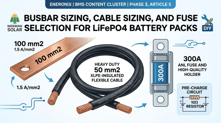
Cable Sizing:
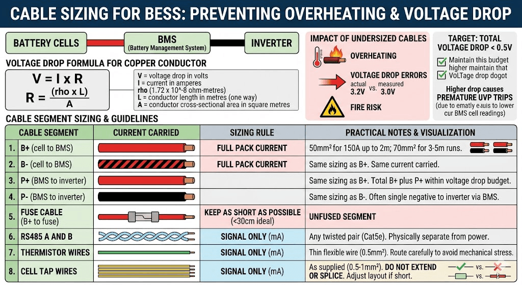
Power cables between cells, BMS, and inverter must be sized for the maximum current they will carry. Undersized cables overheat, cause voltage drop errors, and create fire risk. The calculation is straightforward.
The voltage drop formula for a copper conductor:
V = I x R where R = (rho x L) / A
V = voltage drop in volts
I = current in amperes
rho = copper resistivity = 1.72 x 10⁻⁸ ohm-metres
L = conductor length in metres (one way)
A = conductor cross-sectional area in square metres
Target: total voltage drop across all power cables under maximum load below 0.5V. Higher voltage drop causes the BMS to read cell voltages lower than actual, which can trigger premature UVP trips.
| Cable Segment | Current Carried | Sizing Rule | Practical Notes |
| B+ (cell to BMS) | Full pack current | Same as BMS continuous current rating | 50mm2 for 150A at runs up to 2m. 70mm2 for 150A at 3 to 5m runs. |
| B- (cell to BMS) | Full pack current | Same as BMS continuous current rating | Same sizing as B+. B- carries the same current. |
| P+ (BMS to inverter) | Full pack current | Same as BMS continuous current rating | Same sizing as B+. Keep total cable run (B+ plus P+) within voltage drop budget. |
| P- (BMS to inverter) | Full pack current | Same as BMS continuous current rating | Same sizing as B-. Often a single cable from battery negative to inverter negative via BMS. |
| Fuse cable (B+ to fuse) | Full pack current | Same as B+ | Keep this segment as short as possible. Under 30cm ideal. This is the unfused segment. |
| RS485 A and B | Signal only (mA) | Any twisted pair (Cat5e adequate) | Keep physically separated from power cables. Route in a different cable tray or conduit. |
| Thermistor wires | Signal only (mA) | Thin flexible wire (0.5mm2 adequate) | Route carefully to avoid mechanical stress at the BMS PCB connection point. |
| Cell tap wires | Signal only (mA) | As supplied with BMS (typically 0.5 to 1mm2) | Do not extend or splice. If tap wires are too short, the cell layout must be adjusted. |
Worked Voltage Drop Examples
The following table shows calculated voltage drop for common cable configurations in Nigerian solar installations.
| Cable Spec | Resistance (R = rho x L / A) | Voltage Drop (V = I x R) | Assessment |
| 50mm2, 1m, 150A | 1.72e-8 x 1 / 50e-6 = 0.000344 ohms | 150 x 0.000344 = 0.052V | Acceptable. Under 0.5V budget. |
| 50mm2, 2m, 150A | 1.72e-8 x 2 / 50e-6 = 0.000688 ohms | 150 x 0.000688 = 0.103V | Acceptable. Under 0.5V budget. |
| 50mm2, 3m, 150A | 1.72e-8 x 3 / 50e-6 = 0.001032 ohms | 150 x 0.001032 = 0.155V | Acceptable but approaching limit. Total cable (B+ and P+) should not exceed 5m at 50mm2 for 150A. |
| 25mm2, 1m, 150A | 1.72e-8 x 1 / 25e-6 = 0.000688 ohms | 150 x 0.000688 = 0.103V | Marginal. 25mm2 is undersized for 150A. Use 50mm2. |
| 16mm2, 1m, 150A | 1.72e-8 x 1 / 16e-6 = 0.001075 ohms | 150 x 0.001075 = 0.161V | Undersized. 16mm2 is not suitable for 150A. Will overheat. |
| 70mm2, 5m, 200A | 1.72e-8 x 5 / 70e-6 = 0.001229 ohms | 200 x 0.001229 = 0.246V | Acceptable for 200A at 5m run. Total for B+ and P+ at 5m each would be 0.49V, at the budget limit. |
Rule of thumb from the calculations: for 150A loads, 50mm2 copper cable is correct for runs up to 3 metres. For 200A loads or runs over 3 metres, use 70mm2. For 100A loads, 35mm2 is adequate for runs up to 2 metres.
The complete DC cable sizing framework covering both thermal rating and voltage drop constraints is in our article: DC cable sizing for off-grid solar systems.
The Pre-Charge Circuit
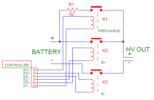
Every modern inverter contains a large capacitor bank on its DC input stage. These capacitors smooth the DC bus voltage and support the inverter’s internal power electronics. When the inverter is first energised from a battery, these capacitors charge from zero volts to full pack voltage.
The speed of that charging is governed by Ohm’s law: I = V / R. With a fully charged 58.4V LiFePO4 pack and a total circuit resistance of perhaps 0.1 ohms (cable resistance plus MOSFET on-resistance), the instantaneous current is 58.4 / 0.1 = 584A. This lasts only a few milliseconds but it is real.
That 584A spike either triggers BMS OCP protection (which trips every time the inverter starts) or, if the OCP threshold is set high enough to accommodate it, passes enough current through the MOSFET switches to stress them each startup. Over hundreds of startups, this stress accumulates.
Pre-Charge Circuit Design
The pre-charge circuit solves this by placing a current-limiting resistor in series with the P+ cable for the first 500ms to 1 second of connection. The resistor limits the capacitor charging current to a safe level. A relay then closes to bypass the resistor for normal operation.
Resistor value calculation:
R_precharge = V_battery / I_limit
Where I_limit is the maximum inrush we want to allow. Target 10 to 20A for a clean pre-charge.
For a 58.4V fully charged pack with I_limit = 10A: R = 58.4 / 10 = 5.84 ohms. Use a 10-ohm resistor for safety margin.
Power rating of the pre-charge resistor: P = I x V = 10A x 58.4V = 584W for the brief inrush period. But the actual duration is 58.4V x C_inverter / (I x R) seconds. For a typical 2,000 microfarad inverter capacitor bank: t = 58.4 x 0.002 / 10 = 0.012 seconds. The energy is 0.5 x 0.002 x 58.4 squared = 3.4 joules. A 10W rated resistor handles this easily for a 12ms pulse. Use a 10W or 20W 10-ohm wirewound resistor.
Pre-Charge Relay Timing
The relay that bypasses the pre-charge resistor should close after 500ms to 1 second. This gives the inverter capacitors time to fully charge through the resistor before the main current path opens. Use a 12V or 24V coil time-delay relay, or wire the relay coil to the inverter’s auxiliary output that activates after the inverter has powered up. Either approach works. The relay contact rating must exceed the full BMS current rating.
| COMMON QUESTION | Some installers ask whether the pre-charge relay can be replaced with a simple manual switch that the installer closes after the inverter is powered up. Yes, this works during commissioning. But it requires a person to be present at every inverter startup. In an automated system that restarts after a grid outage or a fault, no person is present. The capacitor inrush happens unprotected. Use an automatic relay. |
RS485 Communication Wiring: Four Things That Must All Be Correct
Communication between the BMS and the inverter is what separates a smart battery system from a dumb one. The RS485 cable carries cell voltage data, SOC, fault codes, and dynamic operating limits from the BMS to the inverter. Getting the wiring and configuration right requires four things to be correct simultaneously.
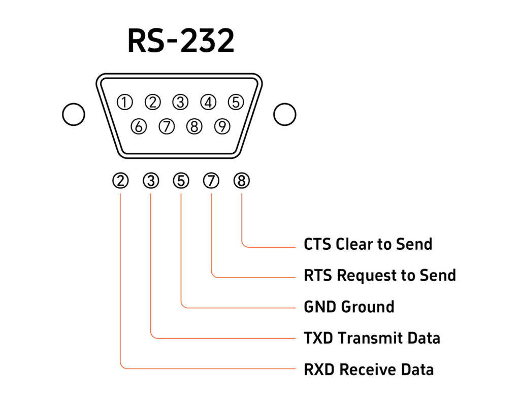
1. Physical Polarity: A to A, B to B, GND to GND
The RS485 A terminal on the BMS connects to the RS485 A terminal on the inverter. RS485 B to B. Add a GND wire between the BMS RS485 GND terminal and the inverter RS485 GND terminal. This GND wire establishes a common voltage reference for the differential signal. Without it, communication appears to work in ideal conditions but fails intermittently as common-mode noise on the power ground shifts the reference between devices.
Reversed A/B polarity (A connected to B) does not damage hardware. It prevents communication. If no communication occurs after correct configuration: swap A and B before investigating any other cause. This is the most common RS485 wiring error and is trivially fixable.
2. Baud Rate: 9600 bps for Most Nigerian Market Inverters
The baud rate must match between BMS and inverter. The standard for solar battery communication in the Nigerian market (Deye, Growatt, Solis) is 9,600 bps. Configure the RS485 baud rate in the BMS app to 9600. Confirm the inverter’s RS485 communication speed is also 9600 bps (check the inverter’s RS485 settings menu).
A baud rate mismatch produces garbled data that the inverter cannot parse. The symptom is communication appears connected at the hardware level (no physical fault indicated) but the inverter shows no battery data or shows nonsensical values.
3. Battery Type Selection in the Inverter
The inverter must be told which BMS protocol to expect. This is set in the inverter’s battery settings menu. Select the option that corresponds to your BMS brand or communication standard. For JK BMS connected to a Deye inverter: navigate to Battery Settings in the Deye menu and select the appropriate lithium battery type. For Pylontech batteries: select PYLON. For generic lithium BMS with RS485: some inverters have a Generic Lithium or Custom option.
Wrong battery type selection means the inverter uses the wrong register map to read BMS data. It receives data from the wrong registers and either shows incorrect values or shows nothing.
The complete inverter-specific configuration guide for Deye, Growatt, Solis, and Victron is in our article: inverter-battery communication protocols in modern solar systems.
4. Cable Routing: Separate From Power Cables
Route the RS485 cable physically separated from power cables. Power cables carrying 100 to 200A generate significant electromagnetic fields during switching transitions. An RS485 cable running parallel to a high-current DC cable for more than 50cm will pick up enough induced noise to cause communication errors, particularly during heavy load cycles.
Use a separate cable tray, conduit, or clip path for the RS485 cable. If it must cross a power cable, cross at 90 degrees rather than running parallel. Cat5e twisted pair provides 20 to 30 dB of common-mode rejection, but this assumes the interference is truly common-mode. Close parallel routing with high-current DC cables can defeat this rejection.
| KEY TAKEAWAY | RS485 communication needs four things correct at once: A to A and B to B polarity, GND wire connected, matching baud rate at 9600 bps, and correct battery type selected in the inverter menu. If communication fails, check all four before assuming a firmware incompatibility. |
The Seven Wiring Mistakes That Destroy BMS Units
These are not theoretical risks. These are the failure modes I see on job sites and in customer support conversations regularly. Every one of them is completely avoidable.
| Wiring Mistake | What Happens and Why | How to Prevent It |
| Cell tap wires connected in wrong order | The BMS cell monitoring IC is permanently damaged on first power-up. The IC measures differential voltages across each cell using adjacent tap wire pairs. A wrong-order connection presents a voltage that exceeds the IC’s maximum input rating in microseconds. | Lay out all tap wires numbered in order before connecting. Have a second person verify the order against the BMS wiring diagram. Connect B0 first, then B1 through B16 in sequence. Never connect B+ before verifying tap wire order. |
| B+ connected before tap wires | Same consequence as wrong tap wire order. The BMS powers up before it has voltage references for all cells. Some BMS firmware reads all channels on power-up; if any channel is floating, the IC input sees unpredictable voltage. | Connect all tap wires completely and verify them against the diagram. Then connect B-. Then connect B+. Power-up order is: tap wires, B-, B+. |
| Thermistors left disconnected | On most JK BMS units, a disconnected thermistor reads as open circuit, which the firmware interprets as maximum temperature. The BMS immediately triggers OTP and refuses to allow charging. The builder thinks the BMS is defective. | Connect thermistors before connecting B+. Even if the thermistor is not in its final mounting position, it must be electrically connected. Mount it properly before commissioning. |
| Inverter connected directly to P+ without pre-charge circuit | Inverter capacitor bank charges from zero to pack voltage in milliseconds. Current spike reaches 200 to 500A. BMS OCP trips. On lower-quality BMS units, the MOSFET gate driver can be damaged by the rapid current transient even if OCP fires correctly. | Install a pre-charge circuit: 50 to 100 ohm 10W resistor with a relay bypass that closes after 500ms. The resistor limits inrush to 0.5 to 1A. After 500ms the relay bypasses and normal operation begins. |
| RS485 A and B reversed | Communication fails immediately. The inverter shows no BMS data and falls back to voltage-based SOC estimation. The builder may spend hours checking BMS firmware compatibility before discovering the polarity is simply reversed. | If communication fails after correct configuration: swap A and B connections and retry before investigating any other cause. Reversed RS485 polarity is the most common communication wiring error. |
| GND wire omitted from RS485 connection | Communication appears to work initially but fails intermittently, especially when one device is powered and the other is not, or when large load currents create common-mode noise on the power ground. Symptoms appear random and are difficult to reproduce. | Always include a GND wire between BMS RS485 GND terminal and inverter RS485 GND terminal. This establishes a common voltage reference for the differential signal. It is not optional. |
| Undersized cables between cells and BMS | High resistance at undersized cable connections causes voltage drop under load. The BMS reads cell voltages that are lower than actual during high-current discharge. This causes premature UVP trips even when cells have capacity remaining. The builder thinks cells are weak when cables are the actual problem. | Calculate cable cross-section using the voltage drop formula. For 150A loads: use 50mm2 copper for runs up to 2 metres. Measure cable temperature after 10 minutes at full load. Hot cables are undersized cables. |
For the broader catalogue of failure modes that develop after installation, including how to diagnose them from BMS app data, see our article: signs of a failing BMS.
Post-Wiring Verification: Seven Checks Before You Call the Job Done
Wiring is not complete until it has been verified. These seven checks should be completed in order before the system is placed in service. A problem found at this stage costs minutes to fix. The same problem found six months later costs a site visit and potentially a degraded battery pack.
| Verification Check | What to Look For and What It Means |
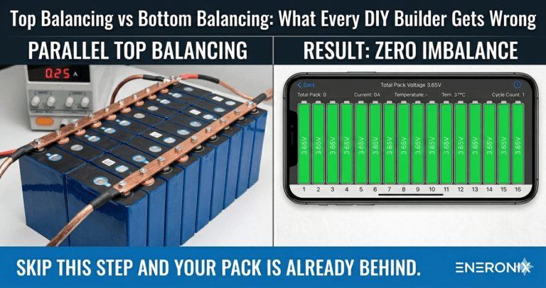
| All 16 cell voltages reading in BMS app | Open BMS Bluetooth app immediately after connecting B+. All 16 cells should read between 3.62V and 3.65V from the top balance. Any cell reading 0V, maximum, or a static incorrect value has a tap wire problem on that channel. |
| Cell voltages match physical multimeter readings | Using a multimeter, measure the voltage across each cell terminal pair. Compare against BMS app readings for the same cell. Readings should agree within 5mV. A large discrepancy on one channel indicates a high-resistance tap wire connection. |
| Temperature readings show ambient values | BMS app should show temperatures within 5 degC of ambient room temperature immediately after power-up. A reading at maximum (or 0 degC if thermistor shows open circuit) means the thermistor is disconnected or has a broken wire. |
| No active fault codes in BMS app | Check the BMS fault status screen before connecting any load. Any active OTP, OVP, or communication fault at this stage must be resolved before proceeding. Do not override or ignore fault codes. |
| Inverter shows SOC as percentage not voltage | Connect the RS485 cable, configure the inverter battery type, and verify the inverter display. SOC showing as a percentage confirms communication is live. Voltage display means communication is not established. |
| BMS and inverter SOC readings agree within 5% | After the first full charge cycle, cross-reference BMS app SOC against inverter SOC display. They should agree within 3 to 5%. A large discrepancy indicates either communication issues or current sensor calibration drift. |
| No hot connections after 10 minutes under load | After running the system under a representative load for 10 minutes, use an IR thermometer on all busbar connections and cable terminals. Any connection warmer than 10 degC above ambient has elevated resistance and must be retorqued or recrimped. |
The full system commissioning protocol covering BMS wiring verification as part of a 10-stage process is in our hybrid solar system commissioning checklist. Use it on every new installation.
Quick Reference: The Wiring Sequence on One Page
For experienced builders who need a reminder checklist rather than the full explanation:
| Step | Action | Verify Before Proceeding |
| 1 | Connect cell tap wires B0 through B16 in order | Verify voltage at each tap point with multimeter before connecting B+ |
| 2 | Connect thermistors T1 and T2 | Both thermistors electrically connected and in contact with cell surfaces |
| 3 | Connect B- cable to BMS B- terminal | Snug connection, cable correctly sized |
| 4 | Connect B+ cable to BMS B+ terminal (fuse in place) | Open BMS app immediately. Verify all 16 cell voltages reading 3.62 to 3.65V |
| 5 | Connect P- to inverter battery negative | No faults in BMS app |
| 6 | Connect pre-charge circuit, then close bypass relay after 500ms | No BMS OCP trip during inverter startup |
| 7 | Connect RS485 cable A, B, and GND | Configure inverter battery type. Verify SOC shows as percentage |
| 8 | Run first full charge cycle | Watch cell voltages in app. No unexpected OVP, OTP, or OCP events |
| 9 | Check all connections with IR thermometer after 10 min load | No connection more than 10 degC above ambient |
| 10 | Check inverter and BMS SOC agreement | Should agree within 5% |
Frequently Asked Questions
What order should I connect the BMS wires?
The correct connection order is: (1) cell tap wires (B0 through B16) first, in sequence, verified against the BMS wiring diagram. (2) Thermistors to T1 and T2. (3) B- power cable. (4) B+ power cable with fuse in place. (5) P- to inverter. (6) Pre-charge circuit between P+ and inverter. (7) RS485 communication cable after power is stable. Never connect B+ before tap wires are all correctly connected. The BMS reads cell voltages immediately on power-up through the tap wires. Wrong tap wire order with B+ connected causes immediate IC damage.
Why does my BMS show 0V on one cell after wiring?
A cell reading 0V in the BMS app after wiring is almost always a disconnected or wrong-position tap wire on that cell’s channel. Check that the tap wire for that cell number is actually connected to the correct cell junction, not to an adjacent junction or left floating. Also check for a broken wire by measuring resistance from the BMS PCB tap terminal to the cell junction with a multimeter (should read under 5 ohms). If the tap wire checks out, the cell monitoring IC on that BMS channel may have been damaged by an earlier wrong-order connection. In that case, the BMS requires replacement.
What happens if I connect BMS tap wires in the wrong order?
The BMS cell monitoring IC is permanently damaged. The IC measures differential voltages across adjacent tap wire channels. When tap wires are in the wrong order, the differential voltage on one or more channels far exceeds the IC’s rated input voltage. This happens in microseconds, before any protection can respond. The symptom is permanently incorrect cell readings on specific channels or complete BMS malfunction after power-up. The BMS must be replaced. Verify tap wire order before connecting B+, every time.
How do I connect the RS485 cable between BMS and inverter?
Connect BMS RS485 terminal A to inverter RS485 terminal A. Connect BMS RS485 terminal B to inverter RS485 terminal B. Connect BMS RS485 GND terminal to inverter RS485 GND terminal. Use a twisted pair cable (standard Cat5e is adequate). Keep the RS485 cable run physically separated from power cables. After connecting, configure the inverter battery type setting to match the BMS protocol, and verify that the inverter display shows SOC as a percentage rather than a voltage reading.
Why is the inverter not recognising my BMS after wiring the RS485 cable?
Physical cable connection alone does not establish communication. Four things must all be correct simultaneously: (1) A and B polarity must be correct (try swapping if communication fails), (2) A GND wire must connect the two devices, (3) The inverter battery type setting must match the BMS protocol, and (4) The RS485 baud rate must match between BMS and inverter (9600 bps is standard for most Nigerian market inverters). Check all four before investigating more complex causes.
How long should BMS power cables be?
As short as physically possible within the enclosure layout. Long cables add resistance, voltage drop, and the potential for inductive interference. For a typical battery enclosure where the BMS is mounted adjacent to the cells: B+ and B- cables under 50cm, P+ and P- cables under 1 metre to the inverter connection point. For longer runs from the battery enclosure to the inverter (up to 5 metres), calculate the cable size using the voltage drop formula: V = I x (rho x L / A). Use 70mm2 cable for 200A loads at 3 to 5 metre runs.
Can I extend the BMS cell tap wires if they are too short?
You should not extend tap wires by splicing. Splice joints add resistance and failure points to a signal path that must be reliable. If tap wires are too short, the solution is to rearrange the cell positions in the enclosure so the BMS can be mounted closer to the cells. If extension is absolutely unavoidable, use the same gauge wire and a proper crimped, soldered, and heat-shrunk joint. Never use twist-and-tape splices on BMS tap wires.
What is a pre-charge circuit and do I really need it?
A pre-charge circuit is a resistor-and-relay combination that limits the inrush current when the inverter is first connected to the battery. Inverters contain large capacitor banks that charge from zero to full pack voltage in milliseconds when the DC circuit is first closed. Without a pre-charge circuit, this creates a current spike of 200 to 500A for 10 to 100 milliseconds.
This spike either trips the BMS OCP protection at every startup, or over time stresses the BMS MOSFETs. The pre-charge circuit limits inrush to 10 to 20A by routing current through a resistor for the first 500ms, then a relay bypasses the resistor for normal operation. For any inverter with DC bus capacitors, which is effectively every inverter, a pre-charge circuit is necessary.
External References
- JK BMS (Jikong Battery) – B2A24S20P wiring diagram and cell tap connection order documentation
- Texas Instruments – BQ76940 cell monitoring IC: maximum input voltage ratings and tap wire connection requirements
- Analog Devices – LTC6804 multicell battery monitor: cell voltage measurement architecture and connection sequence

I am Engr. Ubokobong Ekpenyong, a solar specialist and lithium battery systems engineer with over five years of hands-on experience designing, assembling, and commissioning off-grid solar and energy storage systems. My work focuses on lithium battery pack architecture, BMS configuration, and system reliability in off-grid and high-demand environments.