Do You Always Need a Charge Controller?
Most guides answer this with a flat “yes, always” and move on. That’s not wrong exactly, but it’s incomplete in ways that cost people money, and in some cases, batteries. I’ve watched builders spend the price of a decent MPPT controller on a standalone unit their Deye or Growatt inverter already contains. I’ve also watched a 200Ah LiFePO4 battery get written off because a forum post said a small panel was harmless without one.
The honest answer is conditional. Whether you need a standalone charge controller depends on four things: your battery chemistry, your panel’s actual electrical specifications rather than the watt label, where your system sits architecturally, and what the installation is actually doing. If any one of those is wrong the answer changes.
Here’s what needs to be addressed immediately, because it drives most of the confusion: panel wattage is the wrong metric. Completely wrong. A 10-watt label tells you the panel’s output at laboratory test conditions with a specific load attached. It tells you nothing useful about the voltage that panel presents to your battery terminals at the moment of connection, or the current it will push into a deeply discharged battery. Those numbers are on your panel’s datasheet (Voc and Isc), and they are what actually determine whether unregulated charging causes damage. For a detailed explanation of what those numbers mean and how controllers use them, see our complete guide to solar charge controllers.
The second thing worth stating before going further: a Battery Management System is not a charge controller. LiFePO4 batteries have BMS units that protect cells from fault conditions. They do not regulate incoming charge current, they do not execute a charging algorithm, and they are not a substitute for charge regulation. Treating a standard BMS as a charge controller silently degrades your battery before you ever see a warning sign. If you want to understand exactly what a BMS does and does not protect against, read our breakdown of why lithium batteries need a BMS. With packs running from N150,000 to N600,000 in the Nigerian market, that distinction is expensive to learn the hard way.
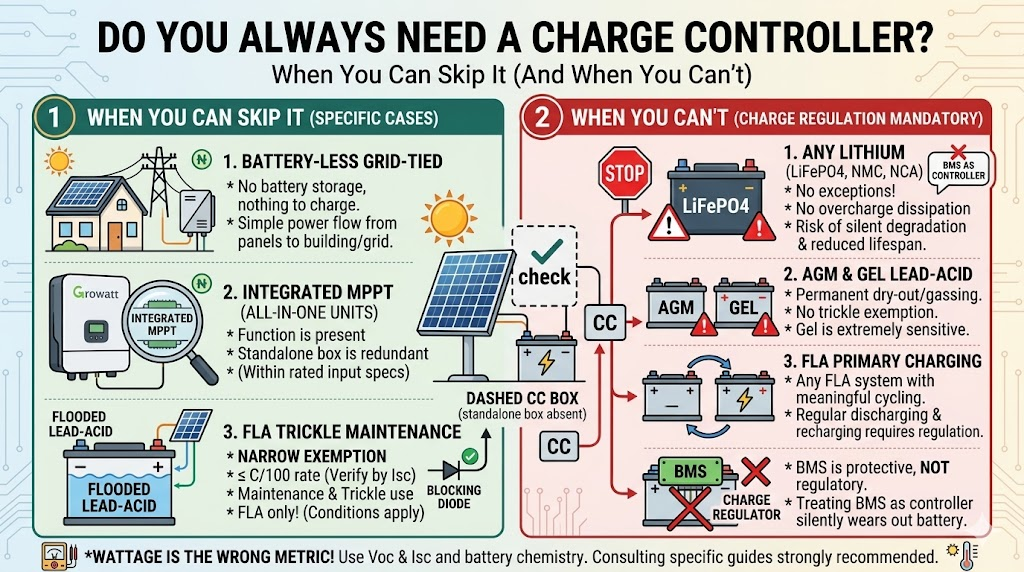
What follows is a framework, not a blanket rule. Battery-less grid-tied systems, properly designed hybrid systems, and integrated all-in-one products are all legitimate cases where a separate charge controller is unnecessary. The trickle maintenance exemption for flooded lead-acid is real, narrow, and chemistry-specific. Everything else needs a controller, and I’ll show you exactly why, chemistry by chemistry.
What a Charge Controller Actually Does And What It Doesn’t
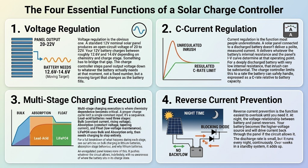
Before deciding whether your system needs one, you need an accurate picture of what a charge controller actually does in a circuit. When people propose alternatives to a charge controller, they’re almost always addressing one of its four functions while ignoring the other three.
The four functions
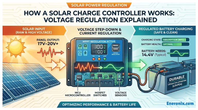
Voltage regulation
Voltage regulation is the obvious one. A standard 12V nominal solar panel produces an open-circuit voltage of 20 to 22V. Your 12V battery charges between roughly 12.6V and 14.6V depending on chemistry and charge stage. Something has to bridge that gap. The charge controller steps panel output voltage down to whatever the battery actually needs at that moment, not a fixed number, but a moving target that changes as the battery fills.
Current regulation
Current regulation is the function most people underestimate. A solar panel connected to a discharged battery doesn’t deliver a polite, measured current. It delivers whatever the battery’s internal resistance and the panel’s I-V curve determine at that operating point. For a deeply discharged battery with very low internal resistance, that inrush can be substantial. The charge controller limits this to a rate the battery can safely handle, expressed as a C-rate relative to battery capacity.
Multi-stage charging execution
Multi-stage charging execution is where chemistry dependence becomes critical. A proper charge cycle isn’t a single constant input; it’s a sequence. Lead-acid batteries need three stages: Bulk (constant current, rising voltage), Absorption (constant voltage, tapering current), and Float (low-voltage maintenance). LiFePO4 uses Bulk and Absorption only, then needs charging to stop entirely. For a full breakdown of what happens during each stage, see our articles on bulk charging in lithium batteries, absorption stage behaviour, and why lithium batteries don’t need float charging. An unregulated panel knows none of this. It pushes whatever the circuit allows, indefinitely, with no awareness of where the battery sits in its charge state.
Reverse current prevention
Reverse current prevention is the function easiest to overlook until you need it. At night, the voltage relationship between battery and panel reverses. Your battery becomes the higher-voltage source and will drive current back through the panel if the circuit allows it. The discharge rate is small, but it runs every night, continuously. Over weeks in a standby system, it adds up.
What a charge controller is not
A charge controller is not a fuse or overcurrent protection device. It manages current within its operating range but does nothing to protect wiring from a fault condition. Fusing belongs at the battery terminal, sized for the wire, and it’s a minimum requirement regardless of what else is in the circuit. For correct sizing, our busbar, cable, and fuse sizing guide for LiFePO4 covers this thoroughly.
It’s not a BMS. It doesn’t monitor individual cell voltages, balance cells, or protect against internal battery faults. It operates at the pack level, not the cell level.
It’s not an inverter. It doesn’t condition power for AC loads. That last boundary matters because designers sometimes look at an all-in-one hybrid inverter (Deye SUN-6K, Growatt SPF 5000, MPP Solar, and similar units that dominate the Nigerian off-grid market) and conclude the charge controller is redundant. In many cases that conclusion is correct, but not because charge regulation is unnecessary. It’s because the inverter’s integrated MPPT input is already performing it. The function is present. The standalone box is what’s absent.
Why Solar Panels Need Regulation
A solar panel is not a battery charger. A battery charger is designed around a specific chemistry: it knows the voltage ceiling, it manages the current, it stages the charge. A solar panel has no awareness of any of this. It produces output according to its I-V curve and delivers whatever that curve dictates at the operating point the load imposes. The battery is that load, and a discharged battery is a demanding one.
The I-V curve and what actually happens at connection
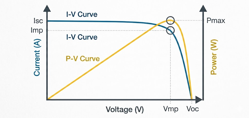
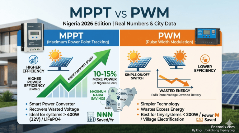
Every panel has an I-V curve mapping its electrical behaviour from one extreme to the other. Short-circuit current (Isc) sits at one end: maximum current, zero voltage. Open-circuit voltage (Voc) sits at the other: maximum voltage, zero current. Maximum power extraction happens between them, at the maximum power point. An MPPT charge controller exists specifically to keep the panel operating there. Our MPPT vs PWM comparison explains why that distinction matters for energy harvest.
Connect a discharged battery directly and the battery’s low voltage pulls the operating point left, toward Isc. How much current actually flows is set by the battery’s internal resistance, which is low when the battery is discharged. The result is higher-than-intended current into the battery at a voltage the battery’s state determines, not any charging algorithm.
For LiFePO4 specifically, self-limiting behaviour is minimal through most of the charge cycle. The flat voltage curve means battery voltage changes very little across 20 to 80 percent state of charge, so the panel continues delivering significant current right up to the point where cells approach maximum voltage. Self-limiting is not the same as regulated, and for lithium chemistry, the self-limiting effect arrives dangerously late.
Open-circuit voltage:
Voc is what the panel presents at its terminals the moment before anything happens: no load, no current, just voltage. For a standard 60-cell 12V nominal panel, that’s 20.5 to 22.5V at STC. When you connect that panel to a 12V battery, the battery doesn’t see 12V. It sees a rapid voltage transient approaching panel Voc at the instant of connection, before current begins to flow and the circuit settles.
For a LiFePO4 battery with a 14.6V ceiling and a BMS that trips at that threshold, this is exactly the fault condition the BMS exists to catch. Catching it once is fine. Catching it every morning at dawn, every time shading lifts, every time the cloud clears and the sun comes back: that is not a designed operating mode for a protection device.
What temperature does to Voc
This detail is almost universally skipped, and in the Nigerian and West African context it runs in both directions, which makes it more important, not less.
Silicon PV panels carry a negative temperature coefficient for Voc, approximately -0.30% to -0.45% per degree Celsius. As panel temperature drops, Voc rises. For cold-weather or overnight calculations, this matters for seasonal or harmattan-period storage systems.
For Lagos and similar hot-climate installations, the more important direction is this: during peak afternoon heat, cell temperatures on a roof-mounted panel can reach 60 to 70 degrees C, not the 25 degrees C STC rating. At 65 degrees C cell temperature with a -0.35%/degC coefficient, a panel with 21.6V STC Voc presents approximately:
Voc(65C) = 21.6 x [1 + (-0.0035 x (65 – 25))] = 21.6 x 0.86 = 18.6V
That’s lower Voc than STC, meaning less open-circuit stress on the battery under peak heat conditions. That’s the good news. The other direction: Isc increases slightly with temperature (positive coefficient, around +0.04%/degC), meaning current delivery is marginally higher on hot days. And peak-sun irradiance in Lagos exceeds the 1000 W/m2 STC standard, pushing Isc further still. An unregulated system in tropical high-irradiance conditions carries a higher current delivery problem precisely on the days the panels are working hardest.
Reverse current:
At night, the electrical relationship between panel and battery reverses. The battery is now the higher-voltage source. If there’s a conductive path back through the panel, current flows in that direction. A panel in darkness isn’t a perfect open circuit; it presents a finite dark resistance through its cell structure. The reverse current is small but runs every night, continuously.
A blocking diode prevents this. A charge controller also prevents it as part of its standard operation. The bypass diodes inside the panel junction box are not blocking diodes. They serve a completely different function, allowing current to route around shaded cell strings. A panel with bypass diodes does not have built-in reverse current protection.
Battery Chemistry Is Everything
The single biggest failure in how this topic gets covered is treating battery chemistry as a footnote. It is not a footnote. It is the primary variable, and every answer that ignores it is either incomplete or wrong.
Flooded lead-acid:
Flooded lead-acid is the only chemistry where the trickle exemption has genuine electrochemical support. When a flooded lead-acid cell overcharges, excess energy drives electrolysis of the water in the electrolyte. The battery gases (hydrogen and oxygen). At sufficiently low charge rates, it functions as a release valve; the battery dissipates overcharge energy through gassing rather than through plate damage. FLA also self-discharges at approximately 3 to 5 percent per month at 25 degrees C, providing an additional buffer at very low charge currents.
That combination (gassing relief and self-discharge) is the electrochemical basis for the C/100 threshold documented in lead-acid battery literature, including IEEE 1561. At a charge rate below one percent of battery capacity, those mechanisms together handle the overcharge energy without meaningful plate damage.
In Lagos and similar hot climates, self-discharge rate increases with temperature. A flooded lead-acid battery in a battery room running at 35 to 40 degrees C may discharge at 6 to 8 percent per month, meaning the self-discharge buffer is actually slightly larger in tropical conditions than in temperate ones. That’s one small factor in your favour. It does not change the practical recommendation: spend N7,000 to N12,000 on a small PWM controller. The exemption is technically defensible, not engineering best practice.
AGM and VRLA:
AGM batteries are lead-acid, which is why people apply FLA trickle logic to them. The sealed construction does not support it. The gas recombination cycle in an AGM cell handles overcharge energy by routing oxygen back to the negative plate where it recombines. Past the recombination capacity, pressure builds inside the sealed case. The relief valve releases at threshold, but repeated pressure cycling degrades the glass mat separator and drives electrolyte dry-out. Unlike flooded lead-acid, you cannot top it up. AGM overcharge damage is permanent. For all practical solar use, treat AGM as requiring a charge controller.
Gel lead-acid: the most sensitive of the three
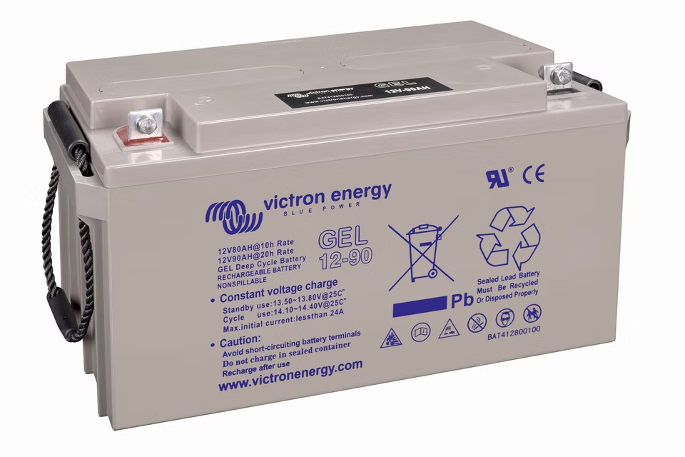
Gel batteries replace liquid electrolyte with silica-gelled acid. The gassing that provides relief in flooded cells damages the gel matrix instead, creating voids that permanently reduce capacity. Gel cells carry a lower voltage ceiling than FLA or AGM, typically 14.0 to 14.2V for a 12V bank. Tighter ceiling, zero gassing tolerance, no exemption. A charge controller is required and must be configured for gel chemistry specifically. A controller set up for flooded lead-acid will overcharge a gel battery.
LiFePO4:
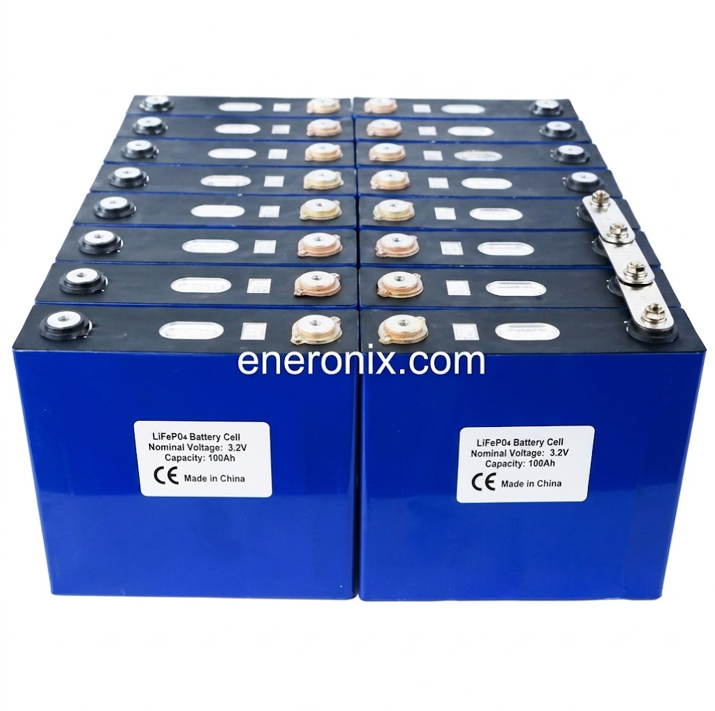
LiFePO4 is where the chemistry discussion gets most consequential, because this is what the majority of Nigerian off-grid builders are now using (Felicity, Jita, Ritar, JK BMS-based DIY packs, Pylontech, BSL) and where the most expensive mistakes are being made. For a broader look at how LiFePO4 compares to other storage chemistries in solar applications, see our best lithium battery chemistry for solar systems article.
The electrochemical reality is unambiguous: LiFePO4 has no overcharge self-relief mechanism of any kind. No gassing, no recombination cycle, no self-discharge buffer worth calculating around. The flat voltage curve compounds this. Across most of the state-of-charge window (roughly 20 to 80 percent capacity), LiFePO4 cell voltage changes very little. The panel delivers current through the flat portion of the curve and continues into the sharp voltage rise near top of charge, where cell stress is highest and where damage accumulates fastest.
A standard 12V nominal panel presents 20 to 22V at the battery terminals on connection. A 12V LiFePO4 bank has a maximum charge voltage of 14.6V and a BMS that trips at that threshold. Every unregulated connection event presents 20-plus volts to a battery with a 14.6V ceiling. The BMS catches it. But every catch is a fault event, and the cells are experiencing that voltage before the BMS can respond.
Low-temperature charging adds a risk layer that unregulated systems cannot address. Below the manufacturer’s specified minimum temperature (for most standard LiFePO4 cells, around 0 degrees C), lithium ions don’t intercalate cleanly into the graphite anode. Metallic lithium plates onto the anode surface instead, permanently reducing capacity. Our article on lead-acid vs lithium charging differences explains why the two chemistries require such fundamentally different approaches at the charger level.
The verdict is unambiguous: charge controller required for LiFePO4, regardless of panel size, BMS quality, or how long the system has appeared to function without one.
NMC and NCA lithium-ion
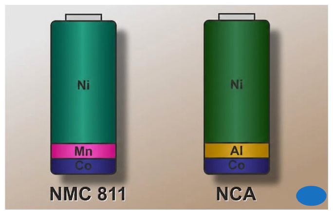
These chemistries appear less frequently in DIY solar storage. Higher nominal cell voltage than LiFePO4 (3.6 to 3.7V versus 3.2V), tighter safe operating window, greater thermal sensitivity, shorter path to thermal runaway under overvoltage. There is no scenario where NMC or NCA cells should be charged from an unregulated solar panel.
Chemistry comparison
| Chemistry | Overcharge relief | Trickle exemption | Controller required | Practical verdict |
| Flooded Lead-Acid | Electrolysis / gassing | Conditional: C/100, FLA only, maintenance use only | Strongly recommended | Exemption exists but narrow. In cold weather, Voc rises while self-discharge buffer shrinks. Use a controller. |
| AGM / VRLA | Gas recombination (limited capacity) | None. Lower tolerance than FLA. | Yes | Required for all practical solar use. |
| Gel Lead-Acid | None effective | None | Yes | Required. Must use gel-specific voltage profile. |
| LiFePO4 | None | None. Chemistry disqualifies it. | Yes, no exceptions | Required regardless of panel size or BMS quality. |
| NMC / NCA | None | None | Yes, higher urgency | Required. Narrower safe window, greater thermal risk than LiFePO4. |
When You Genuinely Don’t Need a Separate Charge Controller
The legitimate cases for omitting a standalone charge controller are more specific than the DIY community generally treats them. In none of these cases is charge regulation absent. The standalone box is what’s missing, not the function it performs.
Scenario 1: battery-less grid-tied systems
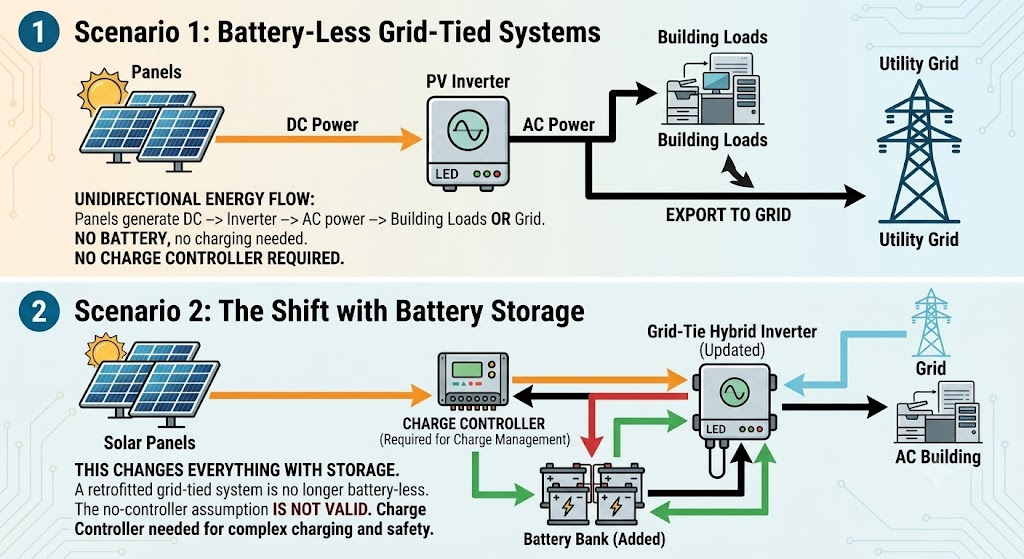
A battery-less grid-tied system moves power in one direction: panels generate DC, the inverter converts to AC, the power feeds building loads or exports to the grid. No battery, nothing to charge, no charge management required. No charge controller needed.
This changes completely the moment battery storage enters the picture. A grid-tied system retrofitted with a battery bank is no longer a battery-less system, and the no-controller assumption from the original installation doesn’t carry forward.
Scenario 2: hybrid and AC-coupled battery systems
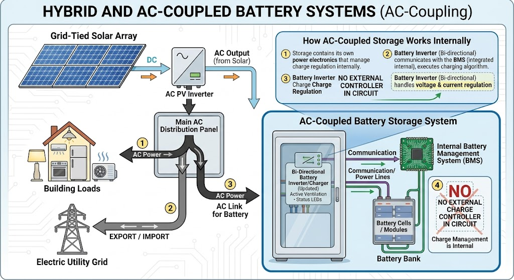
A hybrid system pairs grid-tied solar with battery storage through AC coupling. The storage device contains its own power electronics that manage charge regulation internally. The battery inverter communicates with the BMS, executes the appropriate charging algorithm, and handles voltage and current regulation without any external charge controller in the circuit.
Scenario 3: all-in-one inverter-chargers with integrated MPPT
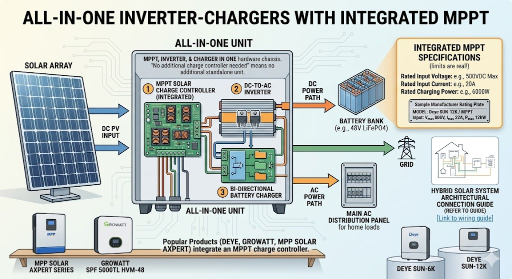
Products like the Deye SUN-6K, Deye SUN-12K, Growatt SPF 5000TL HVM-48, Growatt SPF 6000T DVM, and MPP Solar Axpert series integrate an MPPT charge controller into the same hardware as the inverter and battery charger. When the manufacturer says no additional charge controller is needed, they mean no additional standalone unit. The MPPT input on that device is a charge controller with a rated input voltage, rated input current, and rated charging power. Those limits are real. See our hybrid solar system wiring guide for how these components connect architecturally.
The failure mode I see regularly: a user fills the Deye or Growatt MPPT input to its rated capacity, then adds more panels and connects them directly to the battery bus because the bus is accessible and the wiring looks simple. Those panels are now completely unregulated. The inverter manages the panels it sees through its MPPT input. It has no visibility into the panels bypassing it. If the integrated MPPT is at capacity and more solar is needed, the correct path is a separate charge controller for the additional panels or an inverter with a larger MPPT rating.
Scenario 4: portable solar generators
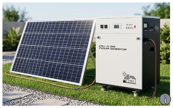
Every mainstream portable solar generator (Jackery, Bluetti, EcoFlow, Goal Zero) ships with an integrated MPPT charge controller inside the unit. The regulation function is present and active every time panels are connected. The useful question is whether the panel you intend to connect is within the unit’s maximum solar input specifications: wattage limit, maximum input voltage, and sometimes maximum input current. Connecting a panel with Voc above the unit’s rated limit risks damaging the integrated controller.
Scenario 5: direct panel-to-DC-load without a battery
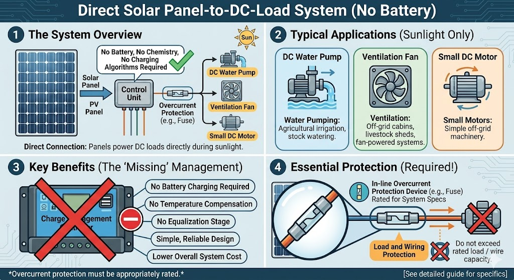
Connect a panel directly to a DC load with no battery in the circuit and the charge management question disappears entirely. No battery, no chemistry to consider, no charging algorithm required. Water pumps, ventilation fans, and small DC motors are the typical applications. Even in this configuration, overcurrent protection appropriate to the wiring and load is still required.
Scenario 6: the narrow trickle exemption for flooded lead-acid
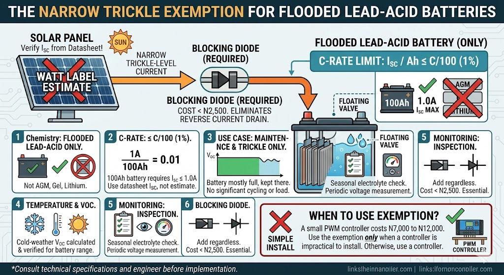
This is the only scenario where connecting a panel directly to a battery without a standalone controller has legitimate engineering support. The conditions that must all be met:
- Chemistry: flooded lead-acid only. Not AGM, not gel, not any lithium chemistry.
- C-rate: Panel Isc divided by battery Ah must be at or below C/100 (one percent of battery capacity). A 100Ah battery requires a panel with Isc at or below 1.0A. Verify by datasheet Isc, not estimated from the watt label.
- Use case: maintenance and trickle only. A battery predominantly at full charge being kept there by a low-level panel. Not a system under regular load where the battery is cycling meaningfully.
- Temperature: cold-weather Voc calculated and verified as acceptable for the battery’s voltage range.
- Monitoring: electrolyte levels inspected seasonally. Battery voltage checked periodically.
Add a blocking diode regardless. It costs under N2,500 and eliminates the reverse current drain. My position: a small PWM controller costs N7,000 to N12,000. Use the exemption only when a controller is genuinely impractical to install. Otherwise, use a controller.
Scenario summary
| Scenario | Battery | Regulation required | Where regulation lives | Separate CC needed |
| Battery-less grid-tied | No | No | N/A | No |
| AC-coupled hybrid system | Yes | Yes | Inside storage inverter | No |
| All-in-one with MPPT (Deye, Growatt, MPP Solar) | Yes | Yes | Inside inverter MPPT input | No (within rated input specs) |
| Portable solar generator | Yes | Yes | Inside the unit | No |
| Direct to DC load, no battery | No | No (compatible loads only) | N/A | No |
| FLA trickle maintenance at C/100 | Yes | Marginal self-regulation only | Panel-to-battery ratio | No, with significant caveats |
| Off-grid with LiFePO4 (Felicity, Pylontech, JK BMS packs) | Yes | Yes, mandatory | Standalone charge controller | Yes |
| Off-grid with AGM | Yes | Yes, mandatory | Standalone charge controller | Yes |
| Off-grid with FLA, primary charging | Yes | Yes | Standalone charge controller | Yes |
The BMS Is Not a Charge Controller
The argument circulates on forums and in YouTube comment sections: my LiFePO4 has a BMS, the BMS catches overvoltage, therefore I don’t need a charge controller. Every part of that reasoning is either wrong or incomplete, and the consequences are expensive enough to deserve a direct technical rebuttal.
What a BMS actually does
A Battery Management System monitors and protects a lithium cell pack at the individual cell level. For the charge controller argument, the key functions are:
- Overvoltage protection (OVP): when any cell reaches its maximum voltage threshold (3.65V per cell for LiFePO4), the BMS disconnects the charge input. For a 12V four-cell pack, this trips at approximately 14.6V at the pack terminals.
- Undervoltage protection (UVP): when any cell drops to its minimum threshold, the BMS disconnects the load to prevent deep discharge damage.
- Overcurrent and short circuit protection.
- Temperature monitoring: quality units prevent charging below the manufacturer’s specified minimum temperature.
- Cell balancing: ensures cells within the pack reach equal voltage. For a detailed look at passive versus active balancing and what each one actually accomplishes, see our active vs passive BMS balancing comparison.
Every one of these functions is reactive. The BMS watches parameters and intervenes when something goes wrong. It does not regulate incoming charge current. It does not execute a charging algorithm. It waits for a fault and disconnects when one arrives.
Some advanced BMS units with CAN bus or RS485 communication (the kind found in Pylontech US3000, BSL, and premium JK BMS units) can signal a charge controller to reduce current before hitting the OVP threshold. That capability requires a charge controller to be present and receiving those signals. For how this communication works in practice, see our article on how lithium batteries communicate with inverters. The BMS communication enhances charge controller performance. It does not replace it.
Protection versus regulation
A charge controller is regulatory. It actively manages voltage and current delivered to the battery throughout the charging cycle, keeping parameters within the battery’s acceptable range. It prevents problematic conditions from developing.
A BMS is protective. It responds to conditions that have already developed and become problematic, by disconnecting the circuit.
Running a solar system with a BMS and no charge controller means relying on a protection device to perform a regulatory function it was not designed for. The battery charges at whatever the panel delivers. Cell voltages rise toward the BMS trip threshold. The BMS disconnects. The panel is still live. The BMS reconnects when voltage drops. The cycle repeats, every charge cycle, indefinitely.
That is not a charging system. It is a fault-response loop running where a charging system should be.
What happens when the BMS trips during active solar input
When a BMS trips overvoltage protection during active charging, it disconnects the battery from the circuit. From the charge controller’s perspective (or the panel’s, if no controller is present), the load it was pushing current into has vanished. With no load to absorb power, the output voltage rises. Quality MPPT controllers from Victron include output overvoltage protection designed for exactly this event. Budget PWM units and lower-tier MPPT controllers, including many of the cheaper Epever and unbranded MPPT units circulating in Nigerian markets, often lack adequate protection. The voltage spike reaches the output terminals and, depending on magnitude, the result ranges from accelerated component wear to immediate hardware failure.
The correct configuration eliminates this entirely: set the charge controller’s absorption voltage 0.1 to 0.2V below the BMS overvoltage protection threshold. For a 12V LiFePO4 battery with OVP at 14.6V, set controller absorption to 14.4V. For a full breakdown of why these thresholds matter more than most installers appreciate, see our article on the dangers of setting BMS cutoffs incorrectly. The controller terminates the charge cycle before the BMS threshold is reached. The BMS never trips during normal charging.
The silent degradation problem
Even in systems where the BMS handles disconnection cleanly, the battery is still being damaged by the operating mode itself. LiFePO4 cell degradation from overvoltage is electrochemically cumulative and functionally invisible until significant capacity loss has already occurred. Cathode oxidation, electrolyte decomposition at the electrode interface, accelerated solid-electrolyte interphase growth: these processes happen silently at elevated cell voltages. For a full explanation of this degradation mechanism, see our article on how charge and discharge cycles affect lithium battery lifespan.
A battery rated for 3,000 cycles to 80 percent capacity under correct operating conditions may reach that threshold in significantly fewer cycles under repeated overvoltage stress. A N200,000 LiFePO4 pack wearing out in 18 months instead of 7 years is not a battery defect. It’s an installation error. The user gets a battery that wore out early, without ever connecting the failure to an installation that appeared to be functioning normally throughout its degraded lifespan.
The warranty dimension
Most LiFePO4 battery manufacturers require a compatible charge controller as a condition of warranty coverage. This requirement lives in the installation documentation, not the marketing materials, which is part of why it gets missed. A battery damaged by direct panel connection or by a BMS-as-controller operating mode is not a warranty claim. It is an installation error, and the manufacturer will correctly decline it.
For batteries in the N150,000 to N600,000 range that characterise the current Nigerian DIY solar market, that’s a meaningful financial exposure. A charge controller that prevents it costs N25,000 to N80,000. The economic case for skipping the controller does not survive a single battery replacement.
How to Calculate Whether Your Panel Requires a Controller
This calculation takes two minutes and requires only your panel’s datasheet. Given that the alternative is guessing from the watt label, which is the wrong metric, those two minutes are worth spending before making any wiring decision.
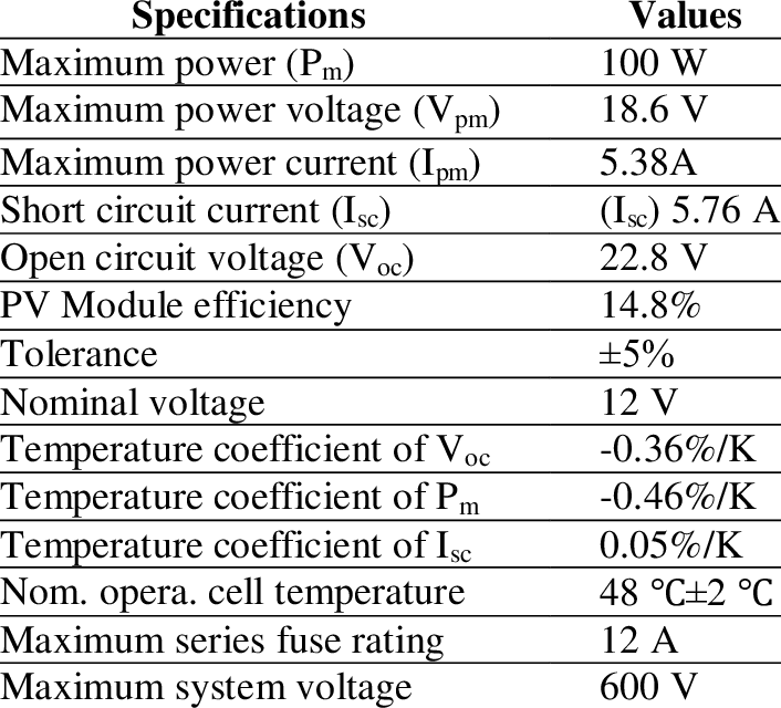
Step 1: find your panel’s Isc and Voc
Both figures are on the panel’s datasheet. If you’ve lost it, they’re printed on the label affixed to the back of the panel.
Isc is short-circuit current, in amps. Maximum current the panel delivers under STC. This is the relevant figure for C-rate calculation because it represents worst-case current into a low-impedance load, which is exactly what a deeply discharged battery presents.
Voc is open-circuit voltage, in volts. Maximum voltage the panel produces with no load. This is what your battery terminals see at the moment of connection. Do not use the watt rating. Do not back-calculate current from watts divided by nominal system voltage.
Step 2: calculate the charge C-rate
C-rate = Panel Isc (A) / Battery Capacity (Ah)
Worked Example A: 5W panel, 100Ah flooded lead-acid. Panel Isc: 0.32A (verify your specific panel). C-rate = 0.32 / 100 = 0.32%. Below C/100. Enters conditional trickle exemption territory for flooded lead-acid only. Continue to Steps 3 through 5.
Worked Example B: 20W panel, 35Ah AGM. Panel Isc: 1.18A. C-rate = 1.18 / 35 = 3.4%. Significantly above C/100. Charge controller required for any chemistry.
Worked Example C: 100W panel, 100Ah LiFePO4. Panel Isc: 5.62A. C-rate = 5.62 / 100 = 5.6%. The C-rate calculation is secondary here. Chemistry disqualifies the exemption entirely. Charge controller required.
Step 3: apply the chemistry filter
If your battery is any lithium chemistry: stop. The C-rate result is irrelevant. Charge controller required.
If your battery is AGM or gel: stop. Charge controller required.
If your battery is flooded lead-acid and C-rate is above C/100: charge controller required.
If your battery is flooded lead-acid and C-rate is at or below C/100: continue to Step 4.
Step 4: check Voc at your minimum expected operating temperature
Voc(T) = Voc(STC) x [1 + (TCV/100) x (T_operating – 25C)]
TCV is the temperature coefficient of Voc from your panel datasheet (negative for silicon panels). For Lagos-region installations, minimum ambient temperatures rarely drive this to a problem threshold for battery voltage safety. For installations at altitude (Jos Plateau, for example) or sites operating through cold harmattan nights, verify the calculation. For series panel configurations this step is critical: two panels in series doubles Voc while Isc remains unchanged.
Step 5: apply the use-case test
The trickle exemption describes a battery that is predominantly full, being maintained by a low-level charge offsetting self-discharge. It does not describe a system under regular load where the battery is being meaningfully cycled. If your battery is regularly discharged by loads and recharged by the panel, the exemption doesn’t apply regardless of panel size or C-rate.
Common Mistakes That Cost Beginners Money and Batteries
Mistake 1: using wattage instead of Isc to evaluate charging risk
A 10-watt panel and a 100-watt panel built on the same cell configuration present nearly identical Voc at the battery terminals. Voc does not scale with wattage. The connection event, where the battery sees the panel Voc transient before current stabilises, is not meaningfully different between a 10-watt and a 100-watt panel of the same nominal voltage class. Pull the datasheet. Use Isc and Voc.
Mistake 2: treating the BMS as the primary charge regulator
The symptom: a LiFePO4 battery losing capacity faster than expected, with a BMS that has logged an unusually high number of overvoltage protection events. The user interprets the logging as evidence the protection system is working. The correct interpretation is that the charging system is misconfigured and the BMS is absorbing the failure, repeatedly, at the cost of its own component lifespan and the battery’s cycle life. For what this degradation pattern looks like from the outside, see our article on signs of a failing BMS. Set the charge controller absorption voltage 0.1 to 0.2V below the BMS overvoltage threshold. The controller terminates the charge. The BMS stays in reserve for actual faults.
Mistake 3: applying the lead-acid trickle exemption to lithium batteries
The C/100 trickle rule for flooded lead-acid has legitimate engineering support and has been documented in battery literature for decades. It has also been stripped of its chemistry qualification, copy-pasted across the internet, and applied to lithium batteries by people who either didn’t notice the original context or assumed the rule was universal. The chemistry distinction is not a technicality. Flooded lead-acid has an overcharge dissipation mechanism. LiFePO4 does not. Applying a rule derived from one mechanism to a chemistry that lacks it is a misapplication, and it results in silent capacity loss.
Mistake 4: using a blocking diode as a charge controller substitute
A blocking diode solves one specific problem: reverse current drain from battery to panel at night. It does nothing for panel Voc at the battery terminals, nothing for current regulation during bulk charging, and nothing for multi-stage charging execution. The three most significant electrical problems with unregulated direct connection remain completely unaddressed. Use a blocking diode as a supplement to a charge controller, not a replacement for it.
Mistake 5: ignoring hot-climate Isc elevation for tropical installations
In Lagos and across the broader West African belt, peak irradiance regularly exceeds 1000 W/m2 STC, particularly during harmattan dry season when atmospheric aerosol loading drops and direct normal irradiance spikes. At 1100 W/m2, a panel’s Isc runs approximately 10 percent above its STC datasheet value. If your panel’s Isc is sitting near the C/100 threshold for the FLA exemption, those conditions may push it above the threshold. Always apply a small conservative margin for tropical high-irradiance conditions when sizing near any threshold.
Mistake 6: setting charge controller absorption voltage at the BMS cutoff threshold
The user installs a LiFePO4 battery, looks up the maximum charge voltage of 14.6V, and sets the controller absorption setpoint to 14.6V to maximise stored energy. The result: the controller’s absorption target matches the BMS overvoltage protection threshold. Any slight overshoot trips the BMS. LiFePO4 batteries store very little additional capacity in the final fraction of a volt before maximum charge voltage. Charging to 14.4V versus 14.6V on a 12V bank typically recovers 98 to 99 percent of rated capacity.
Our article on why 100% maximum usable capacity is a lithium battery death sentence explains the degradation mechanism behind this tradeoff. Set absorption voltage to 14.2V to 14.4V for a 12V LiFePO4 bank as a conservative default. Disable float entirely for LiFePO4.
Mistake 7: adding panels that bypass integrated MPPT inputs
The user has a Deye SUN-6K with a 6000W MPPT input, installs 6kW of panels through it, and then decides to expand. Rather than adding a separate charge controller or upgrading the inverter, they connect new panels directly to the battery bus. Those panels are now completely unregulated. The inverter manages only what passes through its MPPT input. Any panel that needs to charge a battery must connect through a regulation circuit, period.
Mistake 8: concluding safety from six months of visible operation
The logic: I installed this six months ago, the battery works, the system runs, nothing alarming has happened, therefore the installation is correct. Lithium cell degradation from chronic overvoltage does not produce early visible symptoms. The battery continues to charge and discharge normally right up to the point where capacity loss becomes operationally noticeable. By the time the user notices, the process has been underway the entire time they were concluding the installation was safe.
If you want to verify that a lithium battery installation is operating correctly, measure capacity. Discharge the battery under a known load at a consistent rate (typically C/5 or C/10), measure the time to reach the low-voltage cutoff, and calculate the delivered Ah. Compare it to the rated capacity. Establish a baseline at commissioning and repeat annually.
Frequently Asked Questions
Does a LiFePO4 battery with a BMS need a charge controller?
Yes. The BMS and the charge controller perform different functions and neither replaces the other. The BMS monitors cell voltages and disconnects when any cell exceeds its maximum threshold. It is a protection device. The charge controller regulates the voltage and current delivered to the battery throughout the charging cycle. It is a regulatory device. Both are necessary. The BMS does not make the charge controller redundant.
My Deye or Growatt inverter has MPPT built in. Do I still need a separate charge controller?
No, provided all panels connect through the inverter’s MPPT input within its rated specifications. Check the inverter’s maximum PV input voltage: your panel string’s combined Voc at the coldest expected temperature must not exceed this figure. Check the maximum input current or power rating. Panels connected within these limits are regulated correctly. Panels connected directly to the battery bus (bypassing the MPPT input) are not regulated regardless of what the inverter does.
Do I need a charge controller for a 10-watt solar panel?
The watt rating doesn’t answer this question. Isc and battery chemistry do. For any lithium battery, the answer is yes regardless of panel size. A 10-watt panel still presents 20-plus volts Voc to the battery terminals. For flooded lead-acid, calculate C-rate using panel Isc divided by battery Ah. A 10-amp PWM controller costs N7,000 to N12,000 in the Nigerian market, less than the cost of diagnosing a degraded battery, and substantially less than replacing one.
What happens if you connect a solar panel directly to a battery?
Two things happen simultaneously and both are problems. At the moment of connection, the battery sees a rapid voltage transient approaching panel Voc: for a standard 12V nominal panel, that approaches 20 to 22V on a battery with a 14.6V maximum. This occurs every time the panel activates: at dawn, when cloud cover clears, when shading is removed. Once current begins flowing, the panel delivers whatever its I-V curve and the battery’s internal resistance determine at that operating point. There is no charging algorithm, no stage transition, no termination. At night with no reverse current protection, the battery discharges back through the panel at a low but continuous rate.
Can I use a blocking diode instead of a charge controller?
No. A blocking diode is a one-way current gate. It prevents battery voltage from driving current back through the panel at night. That is the only problem it solves. A charge controller solves four problems: voltage regulation, current limiting, multi-stage charging algorithm, and reverse current prevention. A blocking diode addresses only the last of these four. Use it as a supplement to a charge controller, not a replacement.
What charge controller do I need for a small solar setup?
For a system up to 400W with a 12V or 24V battery bank, a 20-amp MPPT controller from a reputable manufacturer covers most small off-grid setups with room to expand. At current Nigerian market prices, the cost difference between a basic 10-amp PWM and a 20-amp MPPT controller is modest (roughly N12,000 versus N35,000 to N55,000 for a mid-range unit), and the MPPT delivers meaningfully more energy from the same panel. For a full sizing methodology, see our MPPT charge controller selection guide. For LiFePO4 specifically, verify that the controller publishes its lithium charging profile voltage setpoints explicitly. If the manufacturer only describes a “lithium mode” without publishing the actual voltage figures, that is insufficient information.
The Final Verdict
By battery chemistry
Flooded Lead-Acid: The narrow trickle maintenance exemption exists and has engineering support. The conditions are specific: panel Isc at or below C/100, flooded lead-acid only, maintenance use only, cold-weather Voc verified, seasonal electrolyte inspection in place. In tropical installations, self-discharge is somewhat higher, but the panel’s Isc may also be somewhat higher from elevated irradiance. Verify both directions. Add a blocking diode regardless. My recommendation: use a controller anyway. A small PWM controller costs N7,000 to N12,000.
AGM and VRLA: Charge controller required for all practical solar applications. Sealed construction removes the overcharge relief mechanism. Damage is permanent.
Gel Lead-Acid: Charge controller required. Tightest voltage ceiling, zero gassing tolerance, no exemption. Configure specifically for gel chemistry.
LiFePO4: Charge controller required. No exceptions based on panel wattage, BMS quality, or how long the system has appeared to function without one. Use a controller with a verified lithium charging profile and configurable setpoints. Set absorption voltage to 14.2V to 14.4V for a 12V bank (verify against your battery manufacturer’s specification). Disable float entirely. Keep at least 0.2V of margin below the BMS overvoltage protection threshold.
NMC and NCA: Charge controller required, with higher urgency than LiFePO4.
By system architecture
Battery-less grid-tied: No charge controller needed. No battery, no charge management function.
Hybrid and AC-coupled battery storage: No separate charge controller needed. Regulation is internal to the storage system.
All-in-one inverter with integrated MPPT (Deye, Growatt, MPP Solar): No separate charge controller needed for panels connected through the MPPT input within rated specifications. Panels bypassing the MPPT input to the battery bus are unregulated regardless of what the inverter does.
Off-grid with any battery: Charge controller required in all cases not covered by the narrow FLA trickle exemption.
The honest bottom line
The cases where a standalone charge controller is genuinely unnecessary are defined and specific. Battery-less grid-tied systems need no charge management because there is nothing to charge. Properly designed hybrid systems and all-in-one products (the Deye and Growatt units that power the vast majority of Nigerian off-grid systems) integrate the regulation function internally, making the standalone unit redundant without making the function absent.
Outside those architectures, if you have a battery and panels that need to charge it, charge regulation is mandatory. The only variable is where that regulation lives, not whether it exists.
The BMS argument fails at the first technical examination. The blocking diode addresses one problem and leaves three others unresolved. Wattage is the wrong metric entirely. Six months of visible operation is not evidence of correct operation. It is evidence only that the system has not yet failed visibly.
A quality charge controller for a small off-grid system costs N25,000 to N80,000 in the Nigerian market. The LiFePO4 battery it protects costs N150,000 to N600,000. Install the controller, configure it correctly for your battery chemistry, verify the setpoints with a multimeter, and set it to terminate charging before the BMS ever needs to intervene.

I am Engr. Ubokobong Ekpenyong, a solar specialist and lithium battery systems engineer with over five years of hands-on experience designing, assembling, and commissioning off-grid solar and energy storage systems. My work focuses on lithium battery pack architecture, BMS configuration, and system reliability in off-grid and high-demand environments.