Introduction
Six months into its service life, a 48V off-grid system installed at a residential property in the dry belt began shutting down every afternoon between 14:00 and 17:00. The shutdowns were clean: the inverter reported a low battery voltage event, the BMS disconnected the bank, and the system restarted when the solar array recharged the bank to the reconnect threshold. The pattern was consistent. Every morning the system operated normally. Every afternoon during the hottest part of the dry season it shut down.
The battery bank had not been undersized in any obvious way. The nameplate capacity was 9.6kWh against a daily demand of 4,916Wh, a ratio that looked comfortable on paper. The errors were three and they compounded each other. The bank had been sized to nameplate capacity without applying the 90 percent DoD limit, which reduced the true usable capacity to 8.64kWh.
It had been sized to one autonomy day, which left no buffer when a dust haze period reduced solar harvest to 60 percent of normal for three consecutive days. And it had been installed in a poorly ventilated enclosure where the afternoon ambient temperature reached 45°C, at which point the Pylontech BMS enforced its high temperature charge cutoff and prevented the array from completing the daily recharge.
None of these were sizing errors in the sense of choosing the wrong product. They were framework errors: the correct variables were not applied to the sizing calculation before the product was selected. This post establishes the three-variable framework that produces a battery bank specification that performs correctly across the full range of conditions the system will encounter in service.
The Three-Variable Sizing Framework
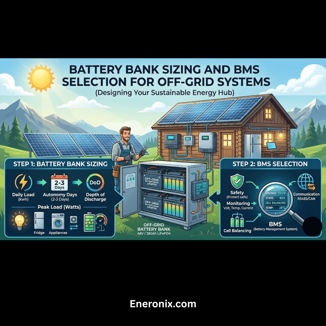
Battery bank sizing requires three variables to be determined before a product can be selected: the daily energy demand, the number of autonomy days the bank must support without solar recharge, and the usable depth of discharge the battery chemistry permits at its rated cycle life. All three variables appear in the governing equation, and undersizing the result of any one of them produces a bank that either runs out of usable capacity before the next recharge, degrades faster than its rated cycle life, or both.
The governing equation for minimum battery bank capacity is:
C_bank = (E_daily x N_autonomy) / DoD_usable
Where:
C_bank = minimum usable bank capacity required (Wh)

E_daily = daily energy demand (Wh) from the load audit

N_autonomy = number of autonomy days required

DoD_usable = usable depth of discharge as a decimal (e.g. 0.90 for 90%)
Applying the three variables to the cluster system. The daily energy demand from the load audit in Post #1 is 4,916Wh. The autonomy day requirement for a coastal West Africa installation with a residential load profile is two days, reflecting the overcast periods of two to three consecutive days that occur several times per year during the rainy season. The usable DoD for LiFePO4 at the C-rates typical of this system is 90 percent:
C_bank = (4,916Wh x 2) / 0.90 = 9,832 / 0.90 = 10,924Wh minimum
The nameplate capacity of the selected battery bank must be at least 10,924Wh. In practice the next standard product size above this figure is selected, as battery banks are not available in arbitrary capacity increments. The autonomy day recommendation varies with application and load criticality as shown below:
| Application | Autonomy Day Recommendation |
| Non-critical residential, reliable solar resource | 1 day minimum |
| Standard residential, coastal West Africa | 2 days standard |
| Critical loads, medical, telecommunications | 3 days minimum |
| Grid-backup only (short outage duration expected) | 0.5 days acceptable |
For the daily energy demand figure that feeds the sizing calculation in this section, refer to our engineering guide on how to conduct a load audit for an off-grid solar system.
Voltage Architecture and Cell Configuration
The voltage architecture of the battery bank must match the system voltage established at the inverter selection stage. For the cluster system, the 48V architecture was selected in Post #8 on the basis that the DC current at 48V for a 3kW discharge is 67.9A, which is manageable with 35mm² cable, whereas the same discharge at 24V produces 135.8A and at 12V produces 271.7A, both of which require cable cross-sections that are impractical in a residential installation.
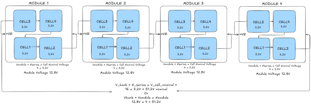
LiFePO4 cells have a nominal voltage of 3.2V per cell. To produce 48V nominal, 16 cells are connected in series:
V_bank = N_series x V_cell_nominal = 16 x 3.2V = 51.2V nominal
The cell voltage limits that the BMS enforces define the operating voltage range of the bank:
V_HVC = 16 x 3.65V = 58.4V  (high voltage cutoff)

V_LVC = 16 x 2.80V = 44.8V  (low voltage cutoff)

16S LiFePO4 Voltage Reference:

Nominal voltage -> 51.2V  (16 x 3.20V/cell)

Absorption voltage -> 57.6V  (16 x 3.60V/cell)

Float voltage -> 53.6V  (16 x 3.35V/cell)

Low voltage cutoff (LVC) -> 44.8V  (16 x 2.80V/cell)

High voltage cutoff (HVC) -> 58.4V  (16 x 3.65V/cell)
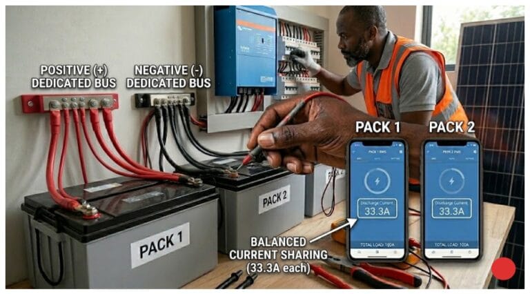
To increase bank capacity beyond a single 16S string, additional 16S strings are connected in parallel. Parallel strings add capacity while maintaining the 51.2V nominal voltage. The minimum parallel string count for a residential system above 10kWh is two, to provide capacity redundancy if one string’s BMS disconnects during a fault event. A single-string bank that loses its BMS connection has zero available capacity. A two-string bank that loses one string retains 50 percent of its capacity, which on a 14.2kWh bank is sufficient to serve critical loads through the night while the fault is diagnosed.
Paralleling more than four strings on a single BMS introduces current imbalance risks during charge and discharge. When strings with slightly different internal resistances are connected in parallel, the lower-resistance string carries a disproportionately higher current share. Above four parallel strings the current imbalance between the highest and lowest resistance strings can exceed the BMS’s ability to manage through its current monitoring alone, and dedicated per-string current monitoring or separate BMS units per string are required.
BMS Functions and Communication Architecture
The BMS is the component that makes lithium chemistry viable in a residential off-grid installation. Without it, the electrochemical failure modes that are latent in every lithium cell, lithium plating at low temperatures, electrolyte oxidation at high cell voltages, copper dissolution at low cell voltages, and thermal runaway from sustained overcurrent, have no active protection mechanism. A LiFePO4 cell that reaches 4.2V during charging does not simply stop accepting charge. It begins oxidizing its electrolyte, generating gas, and if the condition is sustained, it will eventually vent. The BMS is the device that prevents the cell from reaching that condition by monitoring the parameters that approach the failure threshold and disconnecting the bank before they are breached.
The four mandatory BMS functions are cell voltage monitoring and protection disconnect at HVC and LVC, temperature monitoring and protection disconnect at low and high temperature thresholds, current monitoring and protection disconnect at maximum continuous and peak current limits, and state of charge estimation reported to the system monitoring platform.
The communication architecture between the BMS and the charge sources determines the quality of the charge management the system can deliver. A basic BMS communicates through a dry contact relay — a binary stop-go signal. The charge source has no information about the bank’s current state of charge, cell voltage spread, or available charge current headroom. It operates on its own programmed charge profile until the BMS forces a disconnect, at which point the BMS is protecting the battery from the charge source rather than the two devices working together.
A communicating BMS transmits three parameters to the charge sources continuously via CAN bus: the Charge Voltage Limit, the Charge Current Limit, and the Discharge Current Limit. The CVL tells charge sources the maximum voltage they may apply. The CCL tells them the maximum current they may deliver. The DCL tells the inverter the maximum current it may draw. These three parameters change in real time as the bank’s state of charge, temperature, and cell voltage spread change, and the charge sources adjust their output accordingly without requiring a disconnect event.
CVL/CCL/DCL Communication Architecture:
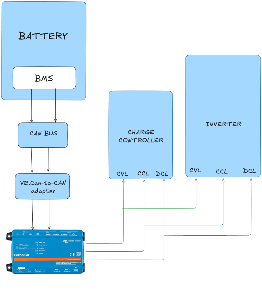
BMS -> monitors cell voltages, temperature, current

BMS -> transmits CVL, CCL, DCL via CAN bus

Cerbo GX -> receives CVL/CCL/DCL from BMS, distributes to charge sources

MPPT 150/60 -> receives CVL and CCL via VE.Can from Cerbo GX, adjusts output

Multiplus-II -> receives CVL and CCL via VE.Bus from Cerbo GX, adjusts charge

Result -> charge sources serve battery; BMS disconnect is last resort not primary control
The Cerbo GX is the communication hub that makes this architecture function. Without it, the BMS CAN bus output has no path to the charge sources and the system reverts to the binary relay architecture regardless of what communication capability the BMS hardware supports. On a system where the BMS communication link fails, the charge sources revert to their locally programmed charge profiles. This is why the locally programmed profile on the MPPT controller and the Multiplus-II must be set to conservative LiFePO4 values that do not exceed the BMS’s HVC threshold even without active communication.
BMS Communication Architecture Checklist:
BMS protocol -> verify CAN implementation: Pylontech, BYD, PACE, or other

Cerbo GX compatibility -> verify battery on Victron supported battery list before specifying

VE.Can-to-CAN adapter -> required for Pylontech CAN to Victron VE.Can interface

Fallback charge profile -> programmed CVL below BMS HVC, CCL below BMS maximum

BMS firmware -> verify current firmware before commissioning

Communication test -> confirm CVL/CCL/DCL visible on Cerbo GX before energising loads
For the MPPT controller and inverter-charger communication requirements that this BMS architecture serves, refer to our engineering guides on how to size and select an MPPT controller for a specific system and how to size and select an off-grid inverter — complete worked example.
Temperature Effects and Installation Requirements
Temperature is the single environmental variable that most directly determines the service life of a LiFePO4 battery bank in a tropical off-grid installation. Its effects operate at both extremes of the operating range through two distinct mechanisms: electrochemical damage at low temperatures during charging, and accelerated degradation of the solid electrolyte interphase layer at sustained high temperatures. In coastal West Africa the low temperature risk is negligible. The high temperature risk is not. It is the primary battery management challenge for any installation in this climate and it is the mechanism that produced the afternoon shutdowns in the introduction.
At temperatures below 0°C, lithium ions cannot intercalate into the graphite anode at the rate the charger attempts to deliver them. The excess lithium plates onto the anode surface as metallic lithium rather than intercalating between the graphite layers. Lithium plating is irreversible: it permanently reduces the anode’s active lithium inventory, reducing capacity, and the plated lithium dendrites can grow through the separator and create an internal short circuit. A quality BMS enforces a low temperature charge cutoff at 0 to 5°C to prevent this, and charging must not be attempted below this threshold under any circumstances including generator charging.
At the high temperature end, the solid electrolyte interphase layer that forms on the anode surface during the first charge cycles is the primary determinant of long-term capacity retention. The SEI layer is chemically stable at temperatures below 40°C and grows slowly throughout the battery’s service life, consuming a small amount of lithium inventory with each charge cycle. Above 45°C the SEI growth rate accelerates significantly, consuming lithium inventory at a rate that produces measurable capacity loss within months rather than years.
The enclosure temperature of a battery bank in a tropical installation is not the same as the equipment room ambient temperature. The cells themselves generate heat during charge and discharge from internal resistance losses. At the C-rates typical of the cluster system, the self-heating adds approximately 5 to 10°C to the enclosure ambient. A battery bank in an equipment room with a 38°C afternoon ambient temperature will reach 43 to 48°C inside the enclosure during a high-rate afternoon discharge, which is at or above the threshold for accelerated SEI growth.
Temperature Installation Checklist:
Low temperature charge cutoff  -> enforced by BMS at 0 to 5°C, verify threshold in BMS config

High temperature charge cutoff -> enforced by BMS at 45°C, verify threshold in BMS config

Equipment room ambient target  -> below 35°C maximum sustained, below 30°C preferred

Direct sunlight shielding -> battery enclosure must not receive direct solar radiation

Roof space installation -> not acceptable in tropical climates (60 to 70°C enclosure temp)

West-facing external wall -> not acceptable, afternoon solar gain exceeds 45°C threshold

Ventilation requirement -> forced ventilation if equipment room ambient exceeds 32°C

Self-heating margin -> add 8°C to equipment room ambient for enclosure estimate

Annual temperature log review  -> Cerbo GX logs battery temperature; review peak values annually
Cycle Life and the DoD-Longevity Trade-off
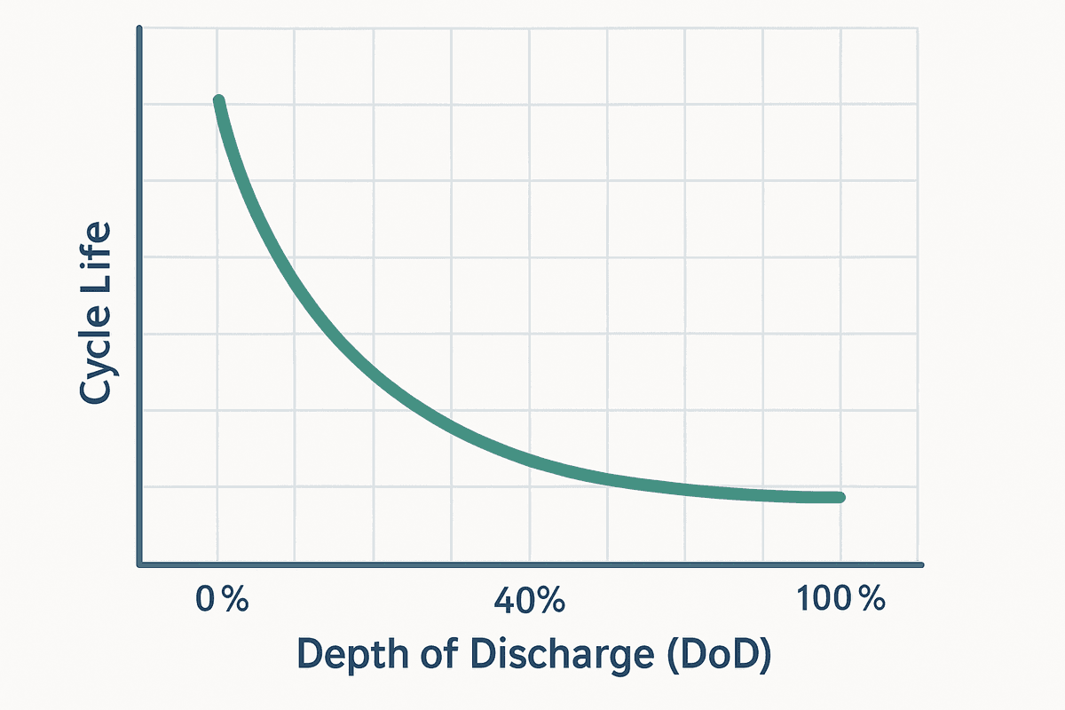
The rated cycle life of a LiFePO4 battery is the number of charge and discharge cycles the cell can complete before its capacity falls to 80 percent of its original nameplate value. For quality LiFePO4 cells at 80 percent DoD, rated cycle life is typically 3,000 to 6,000 cycles. At one full cycle per day, which is the operating pattern of a daily-cycling residential off-grid system, 3,000 cycles represents approximately 8 years of service life and 6,000 cycles represents approximately 16 years. A cycle life figure above 6,000 cycles at 80 percent DoD from an unknown manufacturer warrants scrutiny, as it is at the upper edge of what is achievable with current LiFePO4 chemistry regardless of manufacturing quality.
The most effective single intervention for extending battery service life on a daily-cycling off-grid system is oversizing the bank to reduce the daily depth of discharge. Reducing the daily DoD from 80 percent to 50 percent approximately doubles the cycle life, because the electrochemical stress on the SEI layer and the anode structure is disproportionately higher at deep discharge than at moderate discharge:
DoD-Longevity Trade-off for 4,916Wh Daily Demand:

Bank at 10,924Wh nameplate:

  Daily DoD = 4,916 / (10,924 x 0.90) = 50.0%

  Estimated cycle life at 50% DoD: 6,000 to 10,000 cycles (~16 to 27 years)

Bank at 14,200Wh nameplate (4 x Pylontech US3000C):

  Daily DoD = 4,916 / (14,200 x 0.90) = 38.5%

  Estimated cycle life at 38.5% DoD: well above 10,000 cycles
State of charge estimation on a LiFePO4 bank requires additional attention because the cell voltage curve is nearly flat between 20 and 90 percent SoC. A fully charged LiFePO4 cell at 3.35V and a cell at 50 percent SoC at 3.28V are separated by only 70 millivolts. Voltage-based SoC estimation on a resting bank is unreliable across this range.
Coulomb counting, which integrates the measured charge and discharge current over time, is the primary SoC estimation method used by quality BMS devices. It accumulates a small error with each cycle as the current measurement tolerance compounds over many hundreds of charge and discharge events. The BMS recalibrates its SoC estimate to 100 percent each time the bank completes a full charge to the absorption voltage and holds there until the charge current tapers to the BMS’s end-of-charge threshold, typically 2 to 5 percent of the rated capacity. A bank that never reaches a full charge recalibration event will progressively lose SoC accuracy and the Cerbo GX’s displayed state of charge will drift from the actual value.
Cycle Life Optimisation Reference:
LiFePO4 at 80% DoD -> 3,000 to 6,000 cycles rated life (~8 to 16 years at 1 cycle/day)

LiFePO4 at 50% DoD -> 6,000 to 10,000 cycles rated life (~16 to 27 years)

DoD reduction strategy -> oversize bank beyond minimum; reduces daily DoD materially

SoC estimation method -> coulomb counting primary, voltage-based secondary on resting bank

Full charge recalibration -> absorption voltage held until current tapers to C/20

Recalibration frequency -> at minimum once per month; schedule as maintenance item
Candidate Selection Framework
The candidate selection framework for a battery bank follows the same structure as the MPPT controller and inverter selection frameworks in Posts #7 and #9: establish the minimum specification from the sizing calculation, identify candidate products that meet it on paper, and verify each critical parameter against the system’s actual requirements before committing to a specification.
The six parameters that must be verified for any battery bank candidate are usable capacity against the sizing calculation result, BMS communication protocol against the Cerbo GX supported battery list, continuous discharge current against the inverter’s maximum DC input current, charge current limit against the MPPT controller’s maximum output current, temperature ratings against the installation’s expected ambient range, and warranty cycle count against the target service life.
The BMS communication protocol verification is the parameter most frequently skipped and the one whose omission is most difficult to recover from after the battery bank has been purchased and delivered. Pylontech, BYD, PACE, Seplos, and other manufacturers each implement the CAN bus communication protocol differently. A battery that communicates via CAN bus is not automatically compatible with the Cerbo GX. Victron publishes and maintains a supported battery list that specifies which batteries have been tested and confirmed compatible. A battery not on this list may still communicate correctly, but the integration has not been verified and the CVL/CCL/DCL parameters may not be correctly received and distributed to the charge sources.
The warranty structure offered by different manufacturers covers different aspects of performance. A cycle count warranty guarantees that the battery will complete a stated number of cycles before reaching 80 percent capacity retention. A calendar warranty guarantees performance for a stated number of years regardless of cycle count. A capacity retention warranty guarantees the battery will retain a stated percentage of its original capacity at a stated cycle count or calendar date. The most useful warranty for a daily-cycling residential off-grid system is a cycle count warranty with a capacity retention floor, because it directly addresses the failure mode that matters most: capacity loss from cycling.
Candidate Verification Checklist:
Usable capacity -> C_bank_nameplate x DoD ≥ 10,924Wh minimum

BMS protocol -> verify on Victron supported battery list before purchase

Discharge current -> I_continuous x N_units ≥ 67.9A inverter requirement

Charge current -> I_charge_max x N_units ≥ 60A MPPT output, not exceeded

Temperature ratings -> charge range covers 18°C to 45°C installation envelope

Warranty type -> cycle count warranty with capacity retention floor preferred

Form factor -> rack-mount or wall-mount, ventilation clearances confirmed
Worked Example Battery Bank Sizing and Selection
Applying the three-variable sizing framework to the cluster system establishes the minimum bank capacity before any product is considered:
C_bank = (E_daily x N_autonomy) / DoD_usable
C_bank = (4,916Wh x 2) / 0.90 = 10,924Wh minimum nameplate capacity required

Converting to Ah at 48V nominal:

C_bank_Ah = 10,924Wh / 48V = 227.6Ah minimum
Candidate: Pylontech US3000C
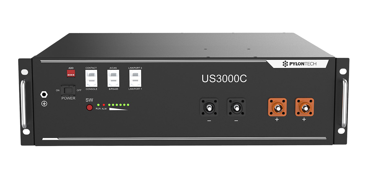
The Pylontech US3000C is a rack-mount LiFePO4 battery module with a nameplate capacity of 3.55kWh and a nominal voltage of 48V. It incorporates an integrated BMS with CAN bus communication using the Pylontech protocol, which is supported on the Victron Cerbo GX supported battery list. Four units in parallel produce a bank of 14.2kWh nameplate capacity.
Verification 1: Usable Capacity
Bank capacity = 4 x 3,550Wh = 14,200Wh nameplate

Usable capacity = 14,200Wh x 0.90 = 12,780Wh

Minimum required = 10,924Wh

12,780Wh > 10,924Wh -> PASS, 17% margin

Daily DoD at rated demand:

DoD_daily = 4,916Wh / 12,780Wh = 38.5%

38.5% DoD, well below 80% limit, cycle life materially extended
Verification 2: Continuous Discharge Current
Pylontech US3000C continuous discharge current = 37A per unit

Available bank discharge current = 4 x 37A = 148A

Inverter maximum DC input current = 67.9A

148A > 67.9A -> PASS, 118% margin
Verification 3: Charge Current Limit
Pylontech US3000C maximum charge current = 25A per unit

Bank maximum charge current = 4 x 25A = 100A

MPPT 150/60 maximum output  = 60A

60A < 100A -> PASS, MPPT output within bank charge limit
Verification 4: Temperature Ratings
Pylontech US3000C charge temperature range = 0°C to 45°C

Pylontech US3000C discharge temperature range = -10°C to 50°C

Installation ambient range = 18°C to 42°C outdoor

Enclosure ambient estimate = 42°C + 8°C self-heating = 50°C peak

50°C enclosure peak exceeds 45°C charge cutoff -> MARGINAL

Required action: forced ventilation to keep enclosure ambient below 37°C

during dry season afternoon peak. Pylontech BMS will enforce charge cutoff

at 45°C automatically if ventilation is insufficient.
Verification 5: BMS Communication
Pylontech US3000C protocol = Pylontech RS485/CAN

Cerbo GX supported = Yes, on Victron supported battery list

Interface required = VE.Can-to-CAN adapter (Victron ASS030520105)

CVL transmitted = 57.6V (16 x 3.60V/cell)

CCL transmitted = 100A  (4 x 25A)

DCL transmitted = 148A  (4 x 37A)

Cerbo GX distributes CVL/CCL to MPPT 150/60 via VE.Can   -> PASS

Cerbo GX distributes CVL/CCL to Multiplus-II via VE.Bus  -> PASS
Verification 6: Warranty
Pylontech US3000C warranty  = 10 years calendar warranty

Cycle count rating = 6,000 cycles to 80% capacity retention at 25°C

At 38.5% daily DoD = cycle life materially exceeds 6,000 cycles

10-year calendar warranty covers expected service life -> PASS
Field Failure Modes
Sizing to nameplate capacity without applying the 90 percent DoD factor reduces the effective bank capacity to 8.64kWh on a 10,924Wh requirement, producing afternoon shutdowns within the first dry season. Specifying a single Pylontech string rather than four parallel units produces a bank with 3.55kWh usable capacity against a 4,916Wh daily demand, which fails the first autonomy day verification.
Omitting the Cerbo GX and the VE.Can-to-CAN adapter produces a system where the Pylontech BMS transmits CVL/CCL/DCL that no charge source receives, and the MPPT controller and Multiplus-II operate on their locally programmed charge profiles rather than the BMS-transmitted limits. Installing the battery bank in an unventilated enclosure in a tropical equipment room produces the 45°C charge cutoff condition that the Pylontech BMS enforces by design, preventing afternoon recharge during the hottest part of the dry season regardless of available solar harvest.
Complete Battery Bank Specification
The four-unit Pylontech US3000C bank satisfies all six verification parameters with the ventilation requirement noted in the temperature verification. The complete battery bank specification for the cluster system is:
Battery Bank Specification Cluster System:
Units -> 4 x Pylontech US3000C rack-mount LiFePO4

Total nameplate capacity -> 14,200Wh (14.2kWh)

Usable capacity -> 12,780Wh at 90% DoD

Daily DoD at rated load  -> 38.5% (4,916Wh / 12,780Wh)

Nominal voltage -> 48V (16S LiFePO4 per unit)

Configuration -> 4 units in parallel, individual fusing per unit at positive busbar

BMS communication -> Pylontech CAN -> VE.Can-to-CAN adapter -> Cerbo GX

CVL (BMS transmitted) -> 57.6V

CCL (BMS transmitted) -> 100A (4 x 25A per unit)

DCL (BMS transmitted) -> 148A (4 x 37A per unit)

Installation requirement -> ventilated enclosure, enclosure ambient below 37°C in dry season

Recalibration schedule -> full charge to absorption monthly, current taper to C/20 confirmed
The BMS communication architecture for this bank within the full system is: Pylontech BMS CAN output → VE.Can-to-CAN adapter (Victron ASS030520105) → Cerbo GX CAN input → Cerbo GX distributes CVL and CCL via VE.Can to SmartSolar MPPT 150/60 and via VE.Bus to Multiplus-II 48/3000. The MPPT controller and Multiplus-II adjust their charge output in real time based on the CVL and CCL received from the Cerbo GX.
Neither charge source will exceed the BMS-transmitted CVL of 57.6V or the CCL of 100A under any operating condition as long as the communication link is active. The locally programmed fallback charge profile on both devices is set to an absorption voltage of 57.2V and a maximum charge current of 55A, which stays below the BMS limits and protects the bank in the event of a communication failure.
The complete system specification across all components confirmed through Posts #6 to #12 is summarised in the table below:
| Component | Selection | Key Parameter | Post |
| Solar array | 6 x 400W, 3S2P | 2,400W, Voc 123V | #4, #5 |
| MPPT controller | Victron SmartSolar 150/60 | 60A output, 150V input | #6, #7 |
| Inverter-charger | Victron Multiplus-II 48/3000 | 3,000VA, 5,500VA surge | #8, #9 |
| DC wiring | 35mm² battery-inverter | 100A ANL fuse | #10 |
| AC distribution | 6-way board, RCBOs, SPD | 16A incomer, Type 2 SPD | #11 |
| Battery bank | 4 x Pylontech US3000C | 14.2kWh, 38.5% DoD | #12 |
| Communication hub | Victron Cerbo GX | CVL/CCL/DCL distribution | #7, #9, #12 |
For the MPPT controller, inverter-charger, and communication hub specifications that interface with the battery bank specified in this post, refer to our engineering guides on how to size and select an MPPT controller for a specific system, how to size and select an off-grid inverter — complete worked example, DC wiring, cable sizing, and fusing for off-grid systems, and AC wiring, earthing, and distribution for off-grid systems.
Conclusion
Battery bank sizing is complete when three conditions are satisfied simultaneously. The usable capacity, nameplate capacity multiplied by the DoD fraction, must meet or exceed the product of the daily energy demand and the autonomy day requirement.
The daily depth of discharge must be low enough that the rated cycle life of the selected cells achieves the target service life at the installation’s operating temperature. And the installation temperature must be controlled to keep the cells within the range where the BMS charge cutoff is not triggered by enclosure ambient during the hottest part of the dry season. A bank that satisfies the first condition but not the second degrades faster than expected. A bank that satisfies the first two but not the third shuts down every afternoon in the dry season, which is the failure mode this post opened with.
The BMS communication architecture is the mechanism that allows the charge sources to work with the battery rather than against it. CVL/CCL/DCL transmitted in real time from the BMS through the Cerbo GX to the MPPT controller and inverter-charger means that the charge profile applied to the bank at every moment is the one the battery’s own management system has determined is appropriate for its current state. A bank protected only by a dry contact relay is a bank that the charge sources are managing blindly, relying on a disconnect event to enforce what continuous communication would have prevented.
With the battery bank specification confirmed, the cluster system is fully specified from the solar array to the load. Every component has been selected through a documented verification process, every cable has been sized to two constraints, every protection device has been rated to protect the cable it serves, and the communication architecture that ties the system together has been verified end to end. The next cluster moves from component specification to system operation: monitoring, commissioning, and fault diagnosis.
For the component specifications and communication architecture that the battery bank connects to in the complete system, refer to our engineering guides on how to size and select an MPPT controller for a specific system, how to size and select an off-grid inverter — complete worked example, DC wiring, cable sizing, and fusing for off-grid systems, and AC wiring, earthing, and distribution for off-grid systems.

I am Engr. Ubokobong Ekpenyong, a solar specialist and lithium battery systems engineer with over five years of hands-on experience designing, assembling, and commissioning off-grid solar and energy storage systems. My work focuses on lithium battery pack architecture, BMS configuration, and system reliability in off-grid and high-demand environments.