Introduction
The DC side of an off-grid system gets the engineering attention. The load audit is done, the array is sized, the controller and inverter are selected through a documented verification process, the cables are sized to two constraints and fused to protect the cable rather than the load. Then the AC distribution board gets wired on the last day of the installation, quickly, by someone who knows how to wire a board and sees no reason why this one should be any different from the grid-connected boards they wire every week.
The difference is the neutral-earth link. And the RCDs. And the SPD that did not get specified because the budget was tight. And the AC and DC cables running through the same conduit because it was easier. None of these omissions produce an immediate fault. The system energises, the loads run, the client signs off. Eight months later a ground fault on a socket circuit keeps the MCB closed, the RCD that was never installed never trips, and a metal appliance chassis sits at 230V until someone touches it.
The AC output of an off-grid inverter is 230V at 50Hz. It has the same shock hazard, the same fire risk from undersized cables, and the same requirement for compliant circuit protection as a utility supply. It must be wired as one. This post applies the same engineering discipline that governed the DC side of this system to every AC cable run, circuit protection device, and earthing connection on the output side of the inverter.
The AC Distribution Architecture
The AC distribution architecture on an off-grid system has the same fundamental structure as a grid-connected residential installation: a source, a main incomer protection device, a distribution board, and individual protected circuits to each load group. What differs is the source characteristics, the neutral-earth arrangement, and the fault loop impedance, all of which affect the selection and configuration of the protection devices. The structure itself is the same because the hazards it must manage are the same.
The source is the inverter’s AC output terminal, which delivers 230V single-phase at 50Hz at a maximum continuous current determined by the inverter’s rated output. For the Victron Multiplus-II 48/3000, the rated AC output current is 13A at 230V, corresponding to the 3,000VA continuous rating. This is the incomer current that the distribution board’s main protection device and incomer cable must be rated to carry continuously.
The four AC cable runs that must be sized and protected independently are as follows. The inverter-to-board incomer run carries the full inverter output current from the inverter’s AC output terminal to the distribution board’s main incomer. The fixed appliance circuits carry current from the distribution board to permanently connected loads such as the air conditioner, refrigerator, and water pump. The socket circuits carry current from the distribution board to socket outlets serving portable and plug-in loads. The outdoor and sub-distribution circuits carry current to external loads or to secondary distribution boards serving separate areas of the building.
| AC Circuit | Typical Current Magnitude |
| Inverter-to-board incomer | 13A maximum (Multiplus-II 48/3000 at 230V) |
| Air conditioner fixed circuit | 7.25A running (1,500W / 230V, PF 0.90) |
| Refrigerator fixed circuit | 1.79A running (350W / 230V, PF 0.85) |
| Lighting circuit | 0.52A running (120W / 230V, PF ~1.0) |
| Socket circuit | 13A maximum (rated circuit capacity) |
The distribution board itself must be specified to accommodate the number of circuits required, with a main incomer isolator or MCB, individual RCBO per outgoing circuit, a neutral bar connecting all neutral conductors, an earth bar connecting all protective earth conductors, a neutral-earth link whose connection state changes with the AC source as covered in Section 4, and a Type 2 surge protection device at the incomer as covered in Section 7.
For the inverter output current rating that determines the incomer specification, refer to our engineering guide on how to size and select an off-grid inverter — complete worked example.
AC Cable Sizing, The Two-Constraint Framework Applied to AC
The two-constraint framework from Post #10 applies directly to AC cable sizing with one modification. The thermal constraint and the voltage drop constraint are identical in structure to the DC calculation. The modification is in how the current is derived from the load power when the load is inductive. On a DC circuit, the current is simply the load power divided by the system voltage. On an AC circuit with an inductive load, the apparent power in VA drives the current drawn from the source, and the apparent power is higher than the real power in watts by a factor determined by the load’s power factor.
For resistive loads (PF = 1.0):
I = P / V
For inductive loads (PF < 1.0):
I = S / V = P / (V x PF)
Where:
I   = line current (A)

P   = real power (W)

S   = apparent power (VA)

V   = supply voltage (V)

PF  = power factor (dimensionless, 0 to 1)
For the air conditioner circuit, the compressor motor presents an inductive load with a typical power factor of 0.90 at running conditions:
I_AC = P / (V x PF) = 1,500W / (230V x 0.90) = 7.25A
The inverter-to-board incomer carries the full inverter rated output. The Multiplus-II 48/3000 is rated at 3,000VA output at 230V:
I_incomer = S / V = 3,000VA / 230V = 13.0A
Applying the two-constraint framework to the incomer cable. Assumed 2 metre one-way giving 4 metres total circuit length. Voltage drop limit of 1 percent of 230V = 2.3V:
A_min = (ρ x L x I) / V_drop_max

A_min = (0.0175 x 4m x 13.0A) / 2.3V = 0.91 / 2.3 = 0.40mm²

Thermal constraint: 4mm² satisfies 13A with tropical derating margin

Cable selected: 4mm² three-core (line, neutral, earth), 90°C insulation
For final circuits serving socket outlets the standard specification is 2.5mm² for circuits up to 16A and 1.5mm² for lighting circuits up to 10A, both of which satisfy the thermal and voltage drop constraints for typical residential circuit lengths. The derating methodology from Post #10 applies directly to AC cables with the same factors for installation method, bundling, and ambient temperature. Cables routed through roof spaces or along south-facing external walls may experience ambient temperatures significantly above the equipment room temperature and must be derated accordingly.
For the full derating methodology and the thermal current rating reference table, refer to our engineering guide on DC wiring, cable sizing, and fusing for off-grid systems.
Circuit Protection, MCBs, RCBOs, and RCDs
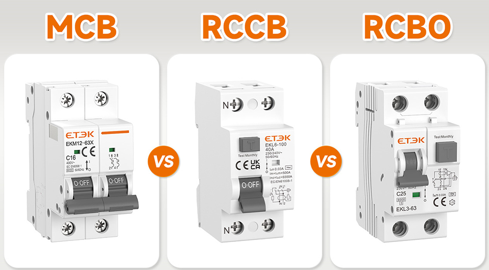
The protection devices in an AC distribution board serve two distinct and non-overlapping functions. Overcurrent and short circuit protection, provided by the MCB element, prevents cables from being damaged by sustained overcurrent or instantaneous fault currents that exceed the cable’s thermal and mechanical ratings. Earth leakage protection, provided by the RCD element, prevents sustained current flow through an unintended path such as a person in contact with a live conductor or a fault from a live conductor to an earthed metal surface.
An MCB alone provides no protection against electric shock. An RCD alone provides no protection against cable overload or short circuit. The RCBO, which combines both functions in a single device, is the correct specification for individual circuit protection on any off-grid residential installation.
The MCB current rating must be selected to protect the cable it feeds, applying the same rule from Post #10: DC Wiring and Cable Sizing Rules for Safe Off-Grid Systems
I_circuit_max < I_MCB_rated ≤ I_cable_derated
The RCD element monitors the vector difference between the current flowing in the live conductor and the current returning in the neutral conductor. Under normal conditions this difference is zero. When current flows through an unintended path, whether through a person, through fault resistance to earth, or through damaged insulation, the difference is non-zero and the RCD trips. The standard trip threshold for personal protection is 30 milliamps, which the RCD must detect and interrupt within 40 milliseconds.
The earth fault loop impedance on an off-grid system is determined by the inverter’s internal output impedance rather than by the utility supply impedance. The inverter’s output impedance is typically higher than the utility supply impedance, which means the fault current produced by a line-to-earth fault on an off-grid circuit is lower than on an equivalent grid-connected circuit.
This lower fault current means the MCB element may not trip instantaneously on a line-to-earth fault, and the circuit may remain energised with the faulted conductor connected to the earthed surface. The RCD element trips on the earth leakage current regardless of the absolute fault current magnitude, which is why RCD protection is the primary personal protection mechanism on off-grid AC circuits.
Circuit Protection Specification by Category:
Inverter-to-board incomer -> 16A MCB (isolator function, no RCD required)

Air conditioner fixed circuit -> 10A RCBO (7.25A running, thermal and earth leakage)

Refrigerator fixed circuit -> 6A RCBO  (1.79A running, compressor inrush protection)

Lighting circuit -> 6A RCBO  (0.52A running, earth leakage on fittings)

Socket circuits -> 16A RCBO (13A maximum, mandatory earth leakage)

Outdoor circuits -> 16A RCBO (mandatory earth leakage, weather exposure)
The Neutral-Earth Link, The Most Misunderstood Wiring Detail
The neutral-earth link is a single conductor or link bar connecting the neutral bar to the earth bar inside the distribution board. On a grid-connected installation it is absent in the consumer unit because the utility transformer provides the neutral-earth bond at the supply point. On an off-grid installation where the inverter is the sole AC source, it must be present because the inverter does not provide a neutral-earth bond externally and without it the AC system has no earth reference, RCDs cannot operate correctly, and any fault from a live conductor to an earthed surface will not be detected.

The consequence of operating an off-grid AC system without a neutral-earth link is not immediately obvious because the system functions normally under fault-free conditions. The inverter produces 230V between line and neutral regardless of whether neutral is bonded to earth. The absence of the bond only becomes apparent when a fault occurs, at which point the RCD has no earth reference current to compare against the live conductor current and cannot detect the leakage. The circuit remains energised with a fault present and the protection device that should have cleared it is unable to operate.
The consequence of operating with a permanent neutral-earth link when the system is connected to the utility grid or a generator is a different failure mode. The utility transformer and the generator both provide their own neutral-earth bond at the source. When the utility or generator source is connected to a distribution board that also has a neutral-earth link, two separate bonds exist in the same system. This creates a closed loop between the two bond points through the neutral conductor, the earth conductor, and the two bond resistances.
Any voltage difference along the neutral conductor under load drives a circulating current through this loop, which flows through the earth conductor as an uncontrolled and unfused current. The practical consequences are nuisance RCD tripping when the grid source is connected, corrosion at earth connections carrying the circulating current, and erratic behaviour of sensitive equipment.
The correct architecture eliminates both failure modes by switching the neutral-earth link with the AC source. When the inverter is the sole source, the link is closed. When the utility or generator is connected, the link is open. The Victron Multiplus-II implements this switching automatically through an internal relay controlled by the inverter’s AC transfer logic. When in inverter mode with no external AC source present, the internal relay closes the neutral-earth bond. When the Multiplus-II detects a valid external AC source and transfers the load, the relay opens the internal bond, leaving the external source’s own bond as the sole neutral-earth reference.
Neutral-Earth Link Configuration by System State:
Inverter only (no grid, no generator)  -> link CLOSED — inverter provides earth reference

Grid connected (utility present) -> link OPEN — utility transformer provides bond

Generator connected -> link OPEN — generator provides its own bond

Victron Multiplus-II -> automatic switching via internal relay

Manual systems -> changeover switch must switch neutral-earth link
On systems without automatic neutral-earth switching, a manual changeover switch between inverter and generator must switch the neutral-earth link simultaneously with the AC source. A changeover switch that transfers the live and neutral conductors but leaves a permanent neutral-earth link in the distribution board is not a compliant installation regardless of whether it prevents backfeed to the generator.
AC Wiring for Off-Grid Solar Systems: Earthing Architecture
The earth electrode is the physical connection between the electrical system and the general mass of earth, and its impedance determines the effectiveness of every earth-referenced protection function in the installation. An RCD that monitors earth leakage current, a fault loop that must carry sufficient fault current to trip an MCB, and a surge protection device that must divert transient energy to earth all depend on a low-impedance path from the distribution board earth bar to the general mass of earth. A high-impedance earth electrode does not prevent these devices from being installed. It prevents them from operating correctly when needed.

The target earth electrode impedance for a residential off-grid installation is below 10 ohms, measured from the earth bar to the general mass of earth. This is achieved in most soil conditions by driving a copper-bonded earth rod of 1.2 to 2.4 metres length vertically into undisturbed soil at a point that remains moist throughout the dry season. In rocky or sandy soils with high resistivity, a single rod may not achieve 10 ohms and a second rod driven 2 metres away and connected in parallel, or a horizontal earth plate buried below the permanent moisture line, is required. The earth impedance must be measured with a dedicated earth resistance tester rather than estimated.
The earth continuity path from the electrode to the distribution board earth bar must be a continuous copper conductor of at least 10mm² cross-section, protected against mechanical damage at any point where it is accessible, and terminated with a compression lug at the earth bar. Every earth connection in the system must be verified for continuity with a low-resistance ohmmeter before the system is energised.
Earth Electrode and Continuity Checklist:
Earth electrode type -> copper-bonded rod, minimum 1.2m length

Earth electrode impedance -> measured below 10 ohms before energising

Earth continuity conductor -> 10mm² minimum, mechanically protected

Earth bar connections -> compression lugs, all circuits individually terminated

DC system bond connection -> from inverter earth terminal to earth bar, not to neutral bar

Earth continuity test -> low-resistance ohmmeter check at every connection

Dry season consideration -> electrode placement at permanent moisture depth
The distinction between the DC system bond and the AC circuit protective earth conductors at the earth bar is the point where the single earth point rule from Post #10 meets the AC earthing architecture. The DC negative bus bonds to the system earth at the inverter’s internal earth terminal, which connects via the inverter’s earth lug to the distribution board earth bar. The AC circuit protective earth conductors connect to the same earth bar as individual connections. The earth bar is the single common earth reference point for both the DC and AC systems, connected to the earth electrode through the continuity conductor.
Generator Input Wiring and Changeover Architecture
The fundamental constraint on generator integration wiring is that the generator output and the inverter AC output must never be connected simultaneously to the same distribution board busbar. Both sources produce 230V AC, but they are not phase-synchronised. Connecting two unsynchronised 230V sources in parallel produces a circulating fault current determined by the phase difference between them and the combined source impedance of both machines. At worst-case phase opposition this fault current can be many times the rated current of either source and will damage both the generator’s alternator windings and the inverter’s output stage before any protection device clears the fault.
On systems using the Victron Multiplus-II, this constraint is satisfied by the inverter-charger’s internal architecture. The Multiplus-II has a single AC input terminal that connects to the generator or grid source, and a single AC output terminal that connects to the distribution board. The internal transfer switch is a break-before-make relay that disconnects the AC output from the inverter before connecting it to the incoming external source. The two sources are never simultaneously present on the AC output terminal, and no external changeover switch is required.
On systems using a standalone inverter paired with a separate battery charger, an external manual or automatic changeover switch must be installed between the generator output, the inverter output, and the distribution board incomer. The changeover switch must be a break-before-make design rated for the full load current, and it must switch the live, neutral, and neutral-earth link simultaneously as covered in Section 4.
The generator input cable must be sized for the generator’s rated output current with a margin for starting surge. A 5kVA generator at 230V produces a rated output current of 21.7A. The input cable must carry 21.7A continuously and the protection device at the generator output terminals must be rated to protect the cable rather than the generator’s internal winding protection.
Generator Integration Wiring Checklist:
Changeover architecture -> Multiplus-II internal relay (preferred) or external break-before-make

Simultaneous source check -> verify no condition allows both sources on same busbar

Generator cable sizing -> rated output current + surge margin, two-constraint framework

Generator output protection -> MCB or isolator at generator terminals, rated to cable capacity

AC input current limit -> programmed in inverter-charger to match generator capacity

Neutral-earth link switching -> automatic on Multiplus-II, manual switch on standalone systems
Surge Protection Devices
Surge protection devices are the component most consistently omitted from off-grid AC distribution boards on cost grounds, and they are the component whose absence is most acutely felt on tropical installations where convective thunderstorm activity produces frequent lightning-induced transient overvoltages on both the generator AC input and any grid connection. A single unprotected surge event can damage every sensitive electronic load connected to the distribution board simultaneously, producing replacement costs that dwarf the cost of the SPD that would have prevented the damage.

A transient overvoltage is a brief, high-amplitude voltage spike superimposed on the AC supply waveform, produced by a nearby lightning strike inducing a current pulse in the AC supply conductors or by the switching of large inductive loads on the same supply. The amplitude of an unprotected transient can reach several kilovolts for a duration of microseconds to milliseconds, which is sufficient to break down the insulation of motor windings, destroy the input rectifier of switching power supplies, and damage the gate oxide of semiconductor devices in variable speed drives and inverter control boards.
A Type 2 SPD installed at the main distribution board incomer clamps the line-to-neutral, line-to-earth, and neutral-to-earth voltages during a transient event by presenting a low-impedance path to earth that diverts the surge current before it reaches the connected equipment. Type 2 SPDs are the correct specification for installation at the distribution board on systems where the incoming supply has already been protected upstream by a Type 1 device at the service entrance, or as the sole protection on systems where no Type 1 is installed at the generator or grid input point.
SPD Specification Reference:
SPD type -> Type 2 at distribution board incomer

Installation point -> between line, neutral, and earth at incomer

Voltage protection level -> Up < 1.5kV for equipment protection

Backup protection -> correctly rated MCB upstream of SPD per manufacturer specification

Replacement indicator -> visual flag or remote indication, inspect after each known surge event

Tropical specification -> minimum 20kA impulse current rating per mode
Cable Routing, Segregation, and Installation Standards
The fundamental segregation requirement is that AC mains voltage cables and DC low-voltage cables must not share the same conduit, trunking, or cable bundle without a physical barrier between them. The reason is twofold. First, a fault on an AC cable that produces arcing or sustained overcurrent generates heat that degrades the insulation of adjacent cables.
DC cables with 48V insulation rating in contact with an arcing 230V AC fault may have their insulation compromised, creating a second fault point that the DC system’s protection devices are not rated to clear. Second, the AC magnetic field from a current-carrying mains cable induces interference voltages in adjacent DC signal and communication cables. On a system where the BMS communicates with the Cerbo GX via a low-voltage CAN bus cable routed alongside the inverter’s AC output cable, this interference can corrupt the communication data and produce erratic BMS behaviour, false alarms, and charge control instability.
The minimum separation distance between AC power cables and DC signal cables in open installation is 50mm. Where they must share a trunking or conduit, a grounded metallic divider between the two cable groups provides both physical separation and electromagnetic shielding. AC power cables and DC power cables at 48V may share a trunking if separated by a divider, but AC power cables and DC communication cables must never share the same enclosure regardless of the divider arrangement.
The cable identification standard must be consistent throughout the installation. Brown for line, blue for neutral, and green-yellow for protective earth are the correct colours under IEC standards applicable in Nigeria and across most of the anglophone West African market. Any deviation from these colours must be permanently marked with colour-coded sleeving at every termination and at every junction box where the cable is accessible.
Cable Routing and Installation Standards Checklist:
AC/DC segregation -> 50mm minimum separation or physical barrier in shared enclosure

AC/DC communication mixing -> never permitted regardless of separation distance

Cable support spacing -> maximum 400mm horizontal runs, 800mm vertical runs

Changes of direction -> cable supported within 300mm of each bend

Roof space routing -> mechanical protection required, high ambient temp derating applies

Cable identification -> line: brown, neutral: blue, earth: green-yellow throughout

Junction boxes -> accessible without dismantling finished surfaces, labelled

Conduit entries -> sealed against insect and moisture ingress at external penetrations

Distribution board labelling -> every circuit labelled with load description and RCBO rating
Worked Example, Complete AC Distribution Specification

Applying the full AC wiring framework to the cluster system produces a complete AC distribution specification from the inverter output terminal to every final circuit. The inverter is the Victron Multiplus-II 48/3000/35-32 with a rated AC output of 3,000VA at 230V and an internal transfer switch handling the neutral-earth link automatically.
Inverter Output to Distribution Board Incomer
Incomer current = 3,000VA / 230V = 13.0A

Cable length = 4m total (2m one-way)

Voltage drop result = (0.0175 x 4 x 13.0) / 2.3V = 0.39mm²  (1% of 230V limit)

Thermal constraint = 4mm² satisfies 13A with tropical derating margin

Cable selected = 4mm² three-core (line, neutral, earth), 90°C insulation

Incomer protection = 16A MCB at distribution board main incomer
Circuit 1: Air Conditioner
Load current = 1,500W / (230V x 0.90) = 7.25A

Cable length = 8m total (4m one-way)

Voltage drop result = (0.0175 x 8 x 7.25) / 6.9V = 0.15mm²  (3% of 230V limit)

Thermal constraint = 2.5mm² satisfies 7.25A for fixed appliance circuit

Cable selected = 2.5mm² three-core, 90°C insulation

Protection = 10A RCBO
Circuit 2: Refrigerator
Load current = 350W / (230V x 0.85) = 1.79A

Cable length = 10m total (5m one-way)

Voltage drop result = (0.0175 x 10 x 1.79) / 6.9V = 0.045mm²  (3% of 230V limit)

Thermal constraint = 1.5mm² satisfies 1.79A for fixed appliance circuit

Cable selected = 1.5mm² three-core, 90°C insulation

Protection = 6A RCBO
Circuit 3: Lighting
Load current = 120W / 230V = 0.52A  (resistive LED loads, PF ~1.0)

Cable length = 20m total (10m one-way)

Voltage drop result = (0.0175 x 20 x 0.52) / 6.9V = 0.026mm²  (3% of 230V limit)

Thermal constraint = 1.5mm² satisfies 0.52A with significant margin

Cable selected  = 1.5mm² three-core, 90°C insulation

Protection = 6A RCBO
Circuit 4: Socket Outlets
Load current = 13A maximum rated circuit capacity

Cable length = 16m total (8m one-way)

Voltage drop result = (0.0175 x 16 x 13) / 6.9V = 0.53mm²  (3% of 230V limit)

Thermal constraint = 2.5mm² satisfies 13A for socket circuit

Cable selected = 2.5mm² three-core, 90°C insulation

Protection = 16A RCBO
The complete AC distribution specification is summarised in the table below:
| Circuit | Current | Cable | Protection | V-Drop |
| Inverter to board incomer | 13.0A | 4mm² | 16A MCB | < 1% 230V |
| Air conditioner | 7.25A | 2.5mm² | 10A RCBO | < 3% 230V |
| Refrigerator | 1.79A | 1.5mm² | 6A RCBO | < 3% 230V |
| Lighting | 0.52A | 1.5mm² | 6A RCBO | < 3% 230V |
| Socket outlets | 13.0A | 2.5mm² | 16A RCBO | < 3% 230V |
The distribution board specification for this installation is a 6-way consumer unit with a 16A main incomer MCB, four RCBO positions as specified above, one spare position for future circuit addition, neutral bar, earth bar, internal neutral-earth link switched automatically by the Multiplus-II’s internal relay, Type 2 SPD at the incomer rated at minimum 20kA impulse current, and a 10mm² earth continuity conductor from the earth bar to the electrode at the Multiplus-II earth terminal.

For the inverter output current rating and AC input current limit configuration that feeds the distribution board specification in this section, refer to our engineering guides on how to select and size an off-grid inverter and how to size and select an off-grid inverter — complete worked example.
Conclusion
The AC side of an off-grid system is not a simplified version of a grid-connected installation. It is a mains installation with the same shock hazard, the same fire risk from undersized cables, and the same requirement for compliant circuit protection, operating from a source with different fault characteristics that make some of those protection requirements more critical rather than less.
The inverter’s higher output impedance relative to the utility supply means fault currents are lower, MCB fast-trip characteristics are less reliable, and RCD protection is the primary personal protection mechanism on every circuit. Specifying MCBs alone on socket circuits because the system is inverter-powered and therefore somehow lower risk is the reasoning that produces the scenario in the introduction.
The four elements that separate a compliant AC installation from a functional but unsafe one are present in the worked example in Section 9: RCBOs on every circuit providing both overcurrent and earth leakage protection, a correctly configured neutral-earth link that switches automatically with the AC source, a Type 2 SPD at the distribution board incomer, and a verified low-impedance earth electrode with continuity confirmed at every connection before energising. None of these elements are expensive relative to the cost of the system they protect. All of them are consistently omitted on installations where the AC distribution board is treated as an afterthought rather than as a mains installation in its own right.
In the next post we move to battery bank sizing, configuration, and BMS selection, completing the component specification for the cluster system and establishing the design framework for the energy storage that every component specified in this cluster is built around.
For the DC wiring, inverter selection, and system architecture that the AC distribution in this post connects to, refer to our engineering guides on DC wiring, cable sizing, and fusing for off-grid systems, how to select and size an off-grid inverter, and how to size and select an off-grid inverter — complete worked example.

I am Engr. Ubokobong Ekpenyong, a solar specialist and lithium battery systems engineer with over five years of hands-on experience designing, assembling, and commissioning off-grid solar and energy storage systems. My work focuses on lithium battery pack architecture, BMS configuration, and system reliability in off-grid and high-demand environments.