Introduction
Two years into its service life, a well-installed off-grid system in a residential property developed a fault that no protection device detected and no monitoring system flagged. The inverter continued operating. The battery continued charging and discharging. The loads ran without interruption. The only evidence of the fault was a faint smell of warm plastic that the occupants had attributed to the inverter running hot in the dry season heat.
When the installation was opened for an unrelated inspection, the technician found the positive cable on the battery-to-inverter run with its insulation softened and charred over a 30-centimetre section adjacent to the battery terminal. The cable had been carrying the inverter’s full DC input current continuously for two years at an ambient temperature that pushed the cable to the edge of its thermal rating every afternoon. The fuse had never tripped because the fuse had been selected to match the inverter’s rated input current rather than the cable’s rated continuous current. The cable was undersized by one cross-section. The fuse was oversized by one step. Neither error would have appeared on a visual inspection at commissioning.
This is the characteristic failure mode of undersized DC cabling in off-grid systems: silent, slow, and detectable only by the thermal damage it produces over months or years. Both errors that produced it are entirely preventable by applying a two-constraint sizing framework to every DC cable run in the system before a single cable is cut.
The Two-Constraint Sizing Framework
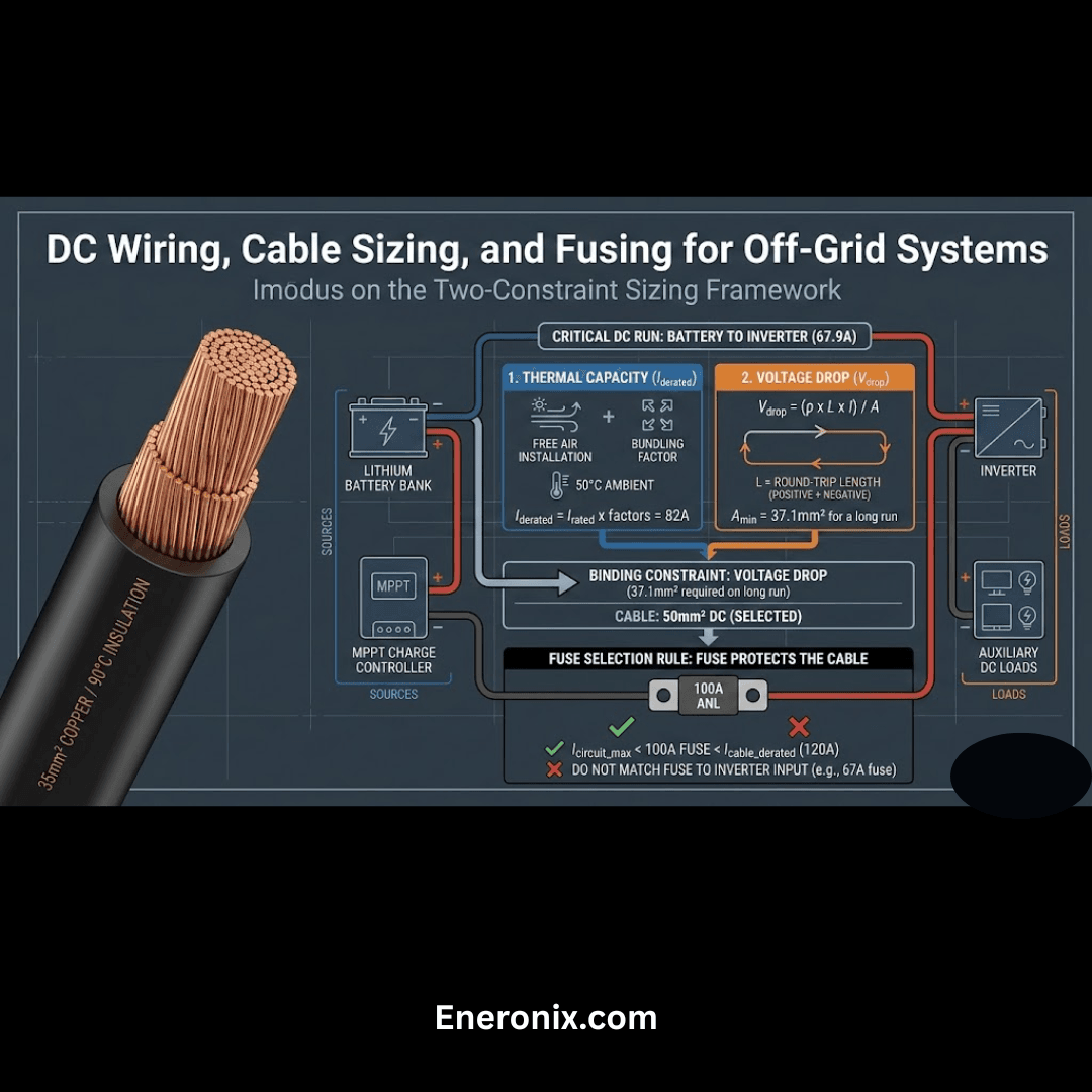
Every DC cable run in an off-grid system must satisfy two independent constraints simultaneously. The first is thermal: the cable must carry the maximum continuous current without exceeding the temperature rating of its insulation. The second is resistive: the voltage drop across the cable run at maximum current must stay within an acceptable fraction of the system voltage.
A cable sized only for thermal capacity on a long run will produce excessive voltage drop that reduces the voltage available to the load and wastes energy as heat in the conductor. A cable sized only for voltage drop on a high-current short run may be thermally adequate but specifies an unnecessarily large cross-section. The correct approach applies both constraints to every run and selects the larger cross-section that satisfies whichever constraint is binding.
The five DC cable runs that every off-grid system must size and fuse independently are as follows. The array string runs carry current from each panel string to the combiner box or directly to the MPPT controller input. The combiner-to-controller run carries the combined array current from the combiner box to the MPPT controller. The controller-to-battery run carries the MPPT controller’s DC output current to the battery bank. The battery-to-inverter run carries the inverter’s full DC input current from the battery bank to the inverter terminals. The battery-to-DC-loads run carries current from the battery bank to any DC load distribution circuits.
Five Critical DC Cable Runs, Typical Current Magnitudes:
Run 1: Array string to combiner -> Isc_STC x f_temp per string (~10 to 12A per string)

Run 2: Combiner to MPPT controller -> combined string current (~20 to 25A for 2-string array)

Run 3: MPPT controller to battery -> controller rated output (~60A for MPPT 150/60)

Run 4: Battery to inverter -> P_AC / (V_DC x η) (~68A for 3kVA at 48V)

Run 5: Battery to DC loads -> sum of DC load currents (system dependent)
For the current magnitudes that feed the cable sizing calculations in this post, refer to our engineering guides on how to size and select an MPPT controller for a specific system and how to size and select an off-grid inverter — complete worked example.
Thermal Current Rating and Derating Factors
The thermal current rating of a DC cable is not a single fixed number. It is a function of the cable’s cross-sectional area, its insulation temperature rating, the method by which it is installed, the number of other cables it is bundled with, and the ambient temperature of the environment it passes through. The published current rating in a cable manufacturer’s datasheet is almost always given for a specific reference condition, typically free air installation at 30 degrees Celsius ambient with no bundling. Every deviation from that reference condition reduces the cable’s effective current carrying capacity, and in a tropical off-grid installation the deviations are significant.

The baseline current ratings for copper DC cable at 30 degrees Celsius in free air with 90°C insulation are the starting point for every thermal calculation:
| Cable Cross-Section | Free Air Rating (A) | Surface Clipped (A) | In Conduit (A) |
| 4mm² | 45A | 43A | 36A |
| 6mm² | 57A | 54A | 46A |
| 10mm² | 76A | 72A | 61A |
| 16mm² | 101A | 96A | 81A |
| 25mm² | 133A | 126A | 106A |
| 35mm² | 158A | 150A | 126A |
| 50mm² | 192A | 182A | 154A |
The 90°C insulation specification is the correct requirement for tropical off-grid installations. Cable with 70°C insulation has a lower thermal margin at the same current and ambient temperature combination, and in an environment where enclosure temperatures regularly reach 45 to 55 degrees Celsius, the difference between 70°C and 90°C insulation is the difference between a cable operating within its thermal design envelope and one that is chronically at or above its insulation rating.
Three derating factors must be applied to the baseline current rating to arrive at the cable’s actual rated current in the installation:
I_derated = I_rated x f_installation x f_bundling x f_temperature
Where:
I_rated = baseline current rating (A)

f_installation = installation method factor: free air 1.0, surface 0.95, conduit 0.80

f_bundling = bundling factor: 1 cable 1.0, 2 cables 0.85, 3 cables 0.79, 6 cables 0.67

f_temperature = ambient temp factor (90°C insulation): 40°C=0.91, 50°C=0.82, 60°C=0.71

Applying all three factors to a 35mm² cable installed in a conduit bundle of three cables at 50 degrees Celsius ambient:

I_derated = 158A x 0.80 x 0.79 x 0.82 = 158A x 0.519 = 82A
A cable with a free-air rating of 158A delivers only 82A in this installation condition. Sizing the cable to its free-air rating without applying derating factors on a tropical installation is not a conservative approach. It is an incorrect approach that produces a cable running above its derated thermal limit every afternoon.
Voltage Drop Calculation of DC cable sizing for off-grid solar

Voltage drop is the second sizing constraint, and on any cable run longer than two to three metres in a 48V system it frequently becomes the binding constraint that determines the minimum cable cross-section. The governing equation for DC voltage drop is:
V_drop = I x R
Where R = (ρ x L) / A
Combined: V_drop = (ρ x L x I) / A
Where:
V_drop = voltage drop across the cable run (V)

I = maximum continuous current (A)

ρ = resistivity of copper = 0.0175 Ω·mm²/m

L = total cable length in metres (positive AND negative conductors combined)

A = cable cross-sectional area (mm²)
The total cable length L in this equation is the round-trip length of the circuit, not the one-way distance between components. A battery-to-inverter run where the positive cable is 1.5 metres and the negative cable is 1.5 metres has a total circuit length of 3 metres. Using only the one-way distance produces a voltage drop calculation that is half the actual value, which is one of the most common errors in DC cable sizing.
Rearranging the equation to solve for the minimum cable cross-section required to stay within a given voltage drop limit:
A_min = (ρ x L x I) / V_drop_max
Where:
A_min = minimum cable cross-section to meet voltage drop limit (mm²)

V_drop_max = maximum acceptable voltage drop (V)
The acceptable voltage drop limits applied to each cable run reflect the sensitivity of the components at each end to voltage variation. For the battery-to-inverter and MPPT controller-to-battery runs, I apply a 1 percent limit of 48V, which is 0.48V. For the array string and combiner-to-controller runs, I apply a 3 percent limit of the string Vmp, which at 102V nominal for the 3S string is approximately 3.06V. For DC auxiliary load runs, I apply a 3 percent limit of 48V, which is 1.44V.
Applying the minimum cross-section equation to the battery-to-inverter run at a 3 metre total circuit length, 67.9A maximum current, and a 0.48V voltage drop limit:
A_min = (0.0175 x 3m x 67.9A) / 0.48V = 3.566 / 0.48 = 7.43mm²
At 3 metres, the thermal constraint requires 35mm² at tropical derated conditions. The voltage drop constraint requires only 7.43mm². The thermal constraint is binding on this short run. At 15 metres on the same circuit:
A_min = (0.0175 x 15m x 67.9A) / 0.48V = 17.83 / 0.48 = 37.1mm²
At 15 metres the voltage drop constraint requires 37.1mm², which exceeds the thermally required 25mm² and becomes the binding constraint. On long runs, voltage drop governs. On short runs, thermal rating governs. Both must be checked on every run.
The Five Critical Cable Runs: Sizing Each One
Applying the two-constraint framework to each of the five cable runs in the cluster system. Current magnitudes are derived from the component specifications established in Posts #6 through #9. Cable lengths are representative of a compact installation with the array on the roof and all DC components within 2 to 3 metres of the battery bank.
Run 1: Array Strings to Combiner Box

Each 3S string carries a maximum current of Isc_STC multiplied by the temperature correction factor. The panel Isc_STC is 10A and the temperature correction factor for a tropical installation is 1.05:
I_string = Isc_STC x f_temp = 10A x 1.05 = 10.5A per string
Voltage drop constraint (15m one-way = 30m total, 3% of 102V Vmp = 3.06V limit):
A_min = (0.0175 x 30m x 10.5A) / 3.06V = 1.80mm²

Thermal constraint: 4mm² satisfies 10.5A with UV and mechanical margin

Cable selected: 4mm² solar-rated dual-insulated UV-resistant DC cable
Run 2: Combiner Box to MPPT Controller

The combiner box combines both strings into a single output carrying the total array current of 21A. Assumed 3 metre one-way run giving 6 metres total circuit length:
Voltage drop constraint (6m total, 3% of 102V Vmp = 3.06V limit):
A_min = (0.0175 x 6m x 21A) / 3.06V = 0.72mm²
Thermal constraint: 6mm² satisfies 21A with installation margin

Cable selected: 6mm² DC cable, 90°C insulation
Run 3: MPPT Controller to Battery

The MPPT controller’s maximum output current is 60A at the Victron SmartSolar MPPT 150/60’s rated output. Assumed 2 metre one-way run giving 4 metres total circuit length:
Voltage drop constraint (4m total, 1% of 48V = 0.48V limit):
A_min = (0.0175 x 4m x 60A) / 0.48V = 8.75mm²
Thermal constraint: 16mm² satisfies 60A derated at tropical ambient

Cable selected: 16mm² DC cable, 90°C insulation
Run 4: Battery to Inverter

The battery-to-inverter run carries the highest current in the system. The maximum DC current for the Multiplus-II 48/3000 at 92 percent efficiency is:
I_DC = P_AC / (V_DC x η) = 3,000W / (48V x 0.92) = 67.9A
Voltage drop constraint (4m total, 1% of 48V = 0.48V limit):
A_min = (0.0175 x 4m x 67.9A) / 0.48V = 9.90mm²
Thermal constraint: 35mm² satisfies 67.9A derated at tropical ambient with margin
Cable selected: 35mm² DC cable, 90°C insulation
Run 5: Battery to DC Auxiliary Loads
DC auxiliary load current is assumed at 15A for monitoring, communications, and auxiliary circuits. Assumed 5 metre one-way run giving 10 metres total circuit length:
Voltage drop constraint (10m total, 3% of 48V = 1.44V limit):
A_min = (0.0175 x 10m x 15A) / 1.44V = 1.82mm²
Thermal constraint: 6mm² satisfies 15A with expansion margin
Cable selected: 6mm² DC cable, 90°C insulation
Fusing: Protecting the Cable, Not the Load

The fundamental rule of DC fusing in off-grid systems is that the fuse protects the cable, not the load. The fuse rating must be greater than the maximum continuous current the circuit will carry, so that the fuse does not trip during normal operation, and equal to or less than the cable’s derated continuous current rating, so that the fuse trips before the cable is thermally damaged if the circuit carries more than its design current:
I_circuit_max < I_fuse_rated ≤ I_cable_derated
Where:
I_circuit_max = maximum continuous current the circuit will carry (A)

I_fuse_rated = fuse rated current (A)

I_cable_derated = cable derated continuous current rating (A)
Applying this to the battery-to-inverter run: the maximum circuit current is 67.9A and the 35mm² cable derated for a tropical compact installation carries approximately 120A. The correct fuse rating is greater than 67.9A and at or below 120A. An 80A or 100A ANL fuse satisfies both conditions. A 150A fuse does not protect the cable because it allows the cable to carry 150A before tripping, which exceeds the cable’s derated current rating.
Fuse Type Selection Reference by Circuit:
Battery to inverter (67.9A) -> 100A ANL fuse at battery positive terminal
MPPT controller to battery (60A) -> 80A ANL fuse at battery positive busbar
Combiner to MPPT (21A) -> 30A MIDI fuse at combiner box output
Array string runs (10.5A each) -> 15A solar string fuse per string at combiner input
DC auxiliary loads (15A) -> 20A blade fuse per circuit at positive busbar
String fusing at the combiner box input protects against reverse current flow when one string in a parallel array is shaded or faulted. The other strings can drive current backwards through the faulted string, potentially exceeding the panel’s reverse current rating. String fuses rated at 1.25 times the string Isc but below the panel’s maximum series fuse rating prevent this. On the cluster system with two strings each at 10.5A, string fuses rated at 15A satisfy the 1.25 times Isc minimum and stay within the panel’s maximum series fuse rating.
Busbar Architecture

The battery connection point is the highest-current node in the entire DC system. Directly connecting multiple DC cables to battery terminals is technically feasible on small systems with two or three connections, but it produces three problems at scale. First, the contact resistance of a shared terminal connection increases with the number of cables sharing it, because the clamping force of a single bolt distributes unevenly across multiple lug faces. Second, the terminal assembly becomes mechanically fragile with thermal cycling, causing bolts to loosen progressively without any visible indication. Third, the absence of individual fusing on each circuit means a fault on any one circuit relies on the main battery fuse for protection.

A copper busbar rated for the full system current resolves all three problems. The positive busbar connects to the battery positive terminal through a single high-current fuse or isolator, and each DC circuit connects to the busbar through its own individually rated fuse. The negative busbar connects directly to the battery negative terminal and provides a single low-resistance return path for all circuits with a single system earth bond.
The busbar cross-section must be rated for the sum of all simultaneously active circuit currents. On the cluster system, the simultaneously active circuits are the battery-to-inverter run at 67.9A and the MPPT controller-to-battery run at 60A feeding in, giving a peak busbar current of approximately 83A in the discharge direction. A copper busbar of 25 x 3mm cross-section provides approximately 200A continuous current capacity in free air, which covers this load with significant margin.
Busbar Architecture Checklist:
Positive busbar -> rated for full simultaneous circuit current, individually fused per circuit

Negative busbar -> rated for full simultaneous circuit current, single earth bond point

Busbar material -> copper, tinned preferred for corrosion resistance in coastal environments

Bolt torque -> specified by manufacturer, checked at commissioning and annually

Fuse holders -> rated for cable current capacity, not just fuse rating

Expansion space -> minimum 25% spare terminals for future circuit additions
Prospective Short Circuit Current and Hardware Ratings
The prospective short circuit current at a lithium battery bank’s positive terminal is the maximum current that would flow if the positive and negative terminals were connected through a zero-impedance path. On a well-assembled LiFePO4 battery bank with low internal resistance cells, this figure can reach 2,000 to 5,000A or higher on a standard residential bank. The prospective short circuit current is estimated from the battery’s internal resistance:
I_sc = V_battery / R_internal
Example: 200Ah LiFePO4 pack, 0.5mΩ per cell, 16 cells in series
R_pack = 16 x 0.0005Ω = 0.008Ω

I_sc = 51.2V / 0.008Ω = 6,400A
Every component in the DC circuit connected directly to this battery bank must be rated for at least 6,400A prospective short circuit current. ANL fuse holders in the quality range specify an interrupting capacity of 6,000 to 10,000A, which covers this application. Standard automotive blade fuse holders specify interrupting capacities of 1,000A or less and are not appropriate for direct battery connection regardless of the continuous current rating.
Terminal lug crimping is the connection point where prospective short circuit current produces the most field failures. A poorly crimped lug has elevated contact resistance and mechanical weakness that are invisible during normal operation but catastrophic during a fault event. The correct crimping tool for copper cable lugs is a hydraulic or ratchet crimping tool with dies matched to the lug barrel diameter. Hand-operated plier-style tools do not produce gas-tight connections on cables above 10mm² and must not be used on any high-current DC connection.
Hardware Rating Checklist:
ANL fuse holders -> verify interrupting capacity ≥ battery prospective Isc

Busbars -> verify fault current rating, not just continuous current

Terminal lugs -> hydraulic or ratchet crimped, matched die to barrel

Isolators -> DC-rated devices, not AC-rated devices repurposed for DC use

Cable insulation -> verify voltage rating ≥ system voltage with margin
Grounding and Bonding
The foundational rule for DC off-grid system grounding is that the DC negative bus is bonded to the system protective earth at exactly one point. This single bond point is typically at the inverter’s internal earth connection or at the main DC distribution board. Victron Multiplus-II units implement the negative-to-earth bond internally when configured for off-grid operation, which means the system earth bond is established at the inverter and no additional bond should be made at the battery negative terminal, the MPPT controller, or any other point in the DC negative bus.
Multiple earth bonds on the DC negative bus create parallel current paths between the bond points through the earth conductor. Any voltage difference between two bond points, which arises from the resistive drop along the DC negative bus under load, drives a current through the earth path. This earth current is not controlled, not fused, and not limited by any protection device. At low levels it produces electrochemical corrosion at every point where it transitions between different metals. At higher levels it produces interference in the low-voltage communication and monitoring circuits that share the same earth reference, causing erratic BMS communication, false alarms on monitoring systems, and unstable inverter behaviour that is extremely difficult to trace to its source.
The distinction between a chassis earth bond and a DC negative earth bond is critical and consistently confused in field installations. The chassis bond connects metal enclosure surfaces to the protective earth for safety, ensuring that a fault from a live conductor to an enclosure surface does not leave the enclosure at a dangerous voltage. This chassis bond is required on every metal enclosure and is entirely separate from the single DC negative bond at the inverter. Adding a DC negative bond at the battery enclosure because it contains metal that should be earthed is the error that creates the ground loop.
Grounding and Bonding Checklist:
DC negative to earth bond -> single point only, at inverter or main DC board

Battery negative terminal -> connected to negative busbar, NOT directly to earth

MPPT controller earth -> chassis bond to protective earth, NOT DC negative bond

Additional metal enclosures -> chassis bonded to protective earth via separate conductor

AC safety earth -> separate conductor to same earth electrode as DC bond

Earth electrode -> copper rod or plate, resistance to earth < 10 ohms

Multiple bond check -> verify with continuity meter before energizing
Complete DC Wiring Specification

The full two-constraint sizing framework applied to all five cable runs produces the following verified specification for the cluster system. Cable lengths are representative of a compact installation with the array on the roof and all DC components within 2 to 3 metres of the battery bank. All current magnitudes are derived from the component specifications established across Posts #6 through #9.
Run 1: Array Strings to Combiner Box
Current per string = 10.5A  (Isc 10A x 1.05 temperature factor)

Cable length = 30m total (15m one-way, roof to combiner)

Voltage drop result = 1.80mm² minimum at 3% Vmp limit

Thermal result = 4mm² minimum with UV/mechanical margin

Binding constraint = Mechanical/UV — thermal and VD both satisfied by 4mm²

Cable selected = 4mm² solar-rated dual-insulated UV-resistant DC cable

Fuse = 15A solar string fuse per string at combiner input
Run 2: Combiner Box to MPPT Controller
Current = 21A  (two strings combined)

Cable length = 6m total (3m one-way)

Voltage drop result = 0.72mm² minimum at 3% Vmp limit

Thermal result = 6mm² minimum for 21A with installation margin

Binding constraint = Thermal

Cable selected = 6mm² DC cable, 90°C insulation

Fuse = 30A MIDI fuse at combiner box output
Run 3: MPPT Controller to Battery
Current = 60A  (Victron SmartSolar MPPT 150/60 rated output)

Cable length = 4m total (2m one-way)

Voltage drop result = 8.75mm² minimum at 1% 48V limit

Thermal result = 16mm² minimum for 60A derated at tropical ambient

Binding constraint = Thermal

Cable selected = 16mm² DC cable, 90°C insulation

Fuse = 80A ANL fuse at battery positive busbar
Run 4: Battery to Inverter
Current = 67.9A  (Multiplus-II 48/3000 at 92% efficiency)

Cable length = 4m total (2m one-way)

Voltage drop result = 9.90mm² minimum at 1% 48V limit

Thermal result = 35mm² minimum for 67.9A derated at tropical ambient

Binding constraint = Thermal

Cable selected = 35mm² DC cable, 90°C insulation

Fuse = 100A ANL fuse at battery positive terminal
Run 5: Battery to DC Auxiliary Loads
Current = 15A  (monitoring, comms, auxiliary DC circuits)

Cable length = 10m total (5m one-way)

Voltage drop result = 1.82mm² minimum at 3% 48V limit

Thermal result = 6mm² minimum for 15A with expansion margin

Binding constraint = Thermal

Cable selected = 6mm² DC cable, 90°C insulation

Fuse = 20A blade fuse per circuit at positive busbar
The complete DC wiring specification is summarised in the table below:
| Cable Run | Current | Cable | Fuse | V-Drop |
| String to combiner (x2) | 10.5A | 4mm² solar | 15A string | < 3% Vmp |
| Combiner to MPPT | 21A | 6mm² | 30A MIDI | < 3% Vmp |
| MPPT to battery | 60A | 16mm² | 80A ANL | < 1% 48V |
| Battery to inverter | 67.9A | 35mm² | 100A ANL | < 1% 48V |
| Battery to DC loads | 15A | 6mm² | 20A blade | < 3% 48V |
The busbar specification for the battery connection point is a tinned copper busbar of 25 x 3mm cross-section for both positive and negative rails, rated at 200A continuous, with a single 125A main isolator between the battery positive terminal and the positive busbar, individual fuse holders for each circuit connection, and a single protective earth bond from the negative busbar to the system earth electrode at the inverter terminal.
For the component current values that feed the cable sizing calculations in this post, refer to our engineering guides on how to size and select an MPPT controller for a specific system, how to select and size an off-grid inverter, and how to size and select an off-grid inverter — complete worked example.
Conclusion
The two failures that produced the silent cable fault in the introduction were not exotic or difficult to prevent. The cable was undersized by one cross-section because the thermal derating calculation was not applied to the installation conditions. The fuse was oversized by one step because it was selected to match the load current rather than the cable’s derated current rating. Two straightforward checks, applied in the correct order, would have caught both errors before the cable was installed.
The two-constraint framework applied in this post produces a verifiable specification for every DC cable run in the system. The thermal constraint establishes the minimum cross-section the cable must have to carry the current without exceeding its insulation rating under actual installation conditions. The voltage drop constraint establishes the minimum cross-section the cable must have to keep resistive losses within acceptable limits at the cable’s length and current. Whichever constraint produces the larger cross-section is the binding constraint for that run, and that cross-section is the correct specification. There is no engineering judgment required in the result. There is only the calculation.
The fusing rule that follows from this framework is equally unambiguous. The fuse protects the cable. Its rating sits between the maximum circuit current and the cable’s derated continuous current rating. A fuse rated above the cable’s derated current rating does not protect the cable regardless of what load it is connected to or what other protection devices exist elsewhere in the system.
In the next post we move to AC wiring, earthing, and distribution, applying the same discipline to the conductors and protection devices on the output side of the inverter.
For the component specifications and current values that feed the DC cable sizing calculations in this post, refer to our engineering guides on how to size and select an MPPT controller for a specific system, how to select and size an off-grid inverter, and how to size and select an off-grid inverter — complete worked example.

I am Engr. Ubokobong Ekpenyong, a solar specialist and lithium battery systems engineer with over five years of hands-on experience designing, assembling, and commissioning off-grid solar and energy storage systems. My work focuses on lithium battery pack architecture, BMS configuration, and system reliability in off-grid and high-demand environments.